Fluke DTX-1800 Technical Reference Handbook
Cableanalyzer
Hide thumbs
Also See for DTX-1800:
- Technical reference handbook (399 pages) ,
- User manual (62 pages) ,
- User manual (56 pages)

Related Manuals for Fluke DTX-1800


Summary of Contents for Fluke DTX-1800
- Page 1 DTX Series CableAnalyzer ™ Technical Reference Handbook April 2004, Rev. 4 1/07 ©2004-2007 Fluke Corporation. All rights reserved. All product names are trademarks of their respective companies.
- Page 2 90 days, unless otherwise stated. Ni-Cad, Ni-MH and Li-Ion batteries, cables or other peripherals are all considered parts or accessories. The warranty extends only to the original buyer or end user customer of a Fluke Networks authorized reseller, and does not apply to any product which, in Fluke Networks’...
-
Page 3: Table Of Contents
Chapter Page Getting Acquainted Overview of Features ............................1-1 Registration ..............................1-2 Additional Resources for Cable Testing Information ..................1-2 Contacting Fluke Networks ..........................1-2 Unpacking ................................1-3 DTX-1800 ..............................1-3 DTX-1200 ..............................1-3 DTX-LT .................................1-4 DTX-MFM2 Multimode Fiber Modules (optional) ..................1-4 DTX-GFM2 Multimode Fiber Modules (optional) ..................1-4 DTX-SFM2 Singlemode Fiber Modules (optional) ..................1-5... - Page 4 Enabling or Disabling the Beeper ......................1-26 Overview of Memory Features ........................1-26 Inserting and Removing the Memory Card ....................1-26 Formatting the Memory Card (DTX-1800 and DTX-1200) or Internal Memory ........1-26 Creating Folders ............................1-27 Setting the Storage Location (DTX-1800 and DTX-1200) .................1-28 Options for Entering Cable IDs ........................1-28...
- Page 5 Table of Contents Step 5: Selecting a Cable ID Source ......................2-4 Certifying Twisted Pair Cabling ........................2-4 Required Equipment ...........................2-4 Step 1: Checking the Battery Status and Verifying Operation with Twisted Pair Adapters ....2-6 Step 2: Selecting a Test Limit, Cable Type, and Outlet Configuration ............2-7 Step 3: Running the Autotest ........................2-8 Step 4: Viewing the Autotest Results ......................2-11 Step 5: Saving the Results ...........................2-12...
- Page 6 DTX Series CableAnalyzer Technical Reference Handbook Autotest on Twisted Pair Cabling ........................3-6 Twisted Pair Autotest Results ..........................3-9 Automatic Diagnostics ..........................3-11 PASS*/FAIL* Results .............................3-12 Wire Map ..............................3-13 Resistance ..............................3-15 Characteristic Impedance ...........................3-16 Length ................................3-17 Propagation Delay and Delay Skew ......................3-18 Insertion Loss ...............................3-19 NEXT (Near-End Crosstalk) ..........................3-21 ACR (Attenuation to Crosstalk Ratio) ......................3-23 Return Loss ..............................3-25...
- Page 7 Table of Contents Certifying Coaxial Cabling Setting the Reference ............................5-1 Coaxial Test Settings ............................5-2 Autotest on Coaxial Cabling ...........................5-5 Coaxial Autotest Results ..........................5-9 HDTDR Analyzer ............................5-10 Resistance ..............................5-10 Impedance ..............................5-10 Length ................................5-10 Propagation Delay ............................5-10 Insertion Loss ...............................5-11 Running Single Tests ............................5-11 Diagnosing Copper Cabling Faults Using the Automatic Diagnostics ........................6-1 Avoiding Tester-Induced Failures ........................6-1...
- Page 8 DTX Series CableAnalyzer Technical Reference Handbook Installing and Removing Fiber Modules ......................7-4 Installing the Connector Adapter ........................7-6 Verifying Operation ............................7-8 Essentials for Reliable Fiber Test Results ......................7-9 Cleaning Connectors and Adapters ......................7-9 About Setting the Reference ........................7-10 Selecting Reference Test Cords ........................7-11 Testing Your Reference Test Cords ......................7-11 Using Mandrels for Testing Multimode Fiber ...................7-11 Fiber Test Settings ............................7-14...
- Page 9 Table of Contents Using FindFiber in Loopback Mode ......................7-49 Using the Power Meter ............................7-51 Running Single Tests ............................7-55 Using the Remote Tester with an OptiFiber Tester ..................7-55 Locating Fibers and Faults with the Visual Fault Locator Visual Fault Locator Applications ........................8-1 Using the Visual Fault Locator ........................8-2 Diagnosing Fiber Cabling Faults Common Causes of Failures ..........................9-1...
- Page 10 Automatically Saving Results ...........................12-3 Working with Folders ............................12-4 Creating a New Folder ..........................12-4 Changing Folders ............................12-4 Deleting Folders ............................12-5 Viewing and Managing Saved Results ......................12-6 Moving or Copying Results to a Memory Card (DTX-1800, DTX-1200) ............12-7 Deleting Results ............................12-7 Renaming Results ............................12-8 viii...
- Page 11 Table of Contents Sorting Results .............................12-8 Formatting a Memory Card (DTX-1800, DTX-1200) or Internal Memory .............12-9 Memory Card Care (DTX-1800, DTX-1200) .....................12-9 Uploading Results to a PC ..........................12-10 Maintenance and Specifications Maintenance ..............................13-1 Reference Procedure for Link Interface Adapters ..................13-1 Factory Calibration ............................13-2...
- Page 12 DTX Series CableAnalyzer Technical Reference Handbook DC Loop Resistance Test ..........................13-18 Measurement Accuracy ..........................13-22 HDTDX Analyzer Specifications for Cables <100 m (328 ft) ..............13-27 HDTDR Analyzer Specifications for Cables <100 m (328 ft) ..............13-27 Characteristic Impedance ..........................13-27 Impulse Noise ..............................13-27 DTX-COAX Coaxial Adapter Specifications ....................13-28 DTX-NSM Module Specifications ........................13-30 DTX-MFM2/SFM2/GFM2 Fiber Module Specifications ................13-31...
- Page 13 Table of Contents Appendices Fiber Test Method Reference Tables Loss Test Methods for Fiber Cabling Introduction ..............................B-1 Method A/A.2 ..............................B-2 Method B/A.1 ..............................B-4 Method C/A.3 ..............................B-6 Modified Method B ............................B-8 The Alternate Method .............................B-11 Index...
- Page 14 DTX Series CableAnalyzer Technical Reference Handbook...
-
Page 15: List Of Figures
List of Figures Figure Page Tester Front Panel Features..........................1-8 Tester Side and Top Panel Features .........................1-10 Smart Remote Features ............................1-12 Charging and Removing the Battery ......................1-15 Checking the Battery Status ..........................1-17 Attaching and Removing Adapters .........................1-18 Handling Guidelines for Permanent Link Adapters ..................1-19 Changing the Personality Module on a DTX-PLA001 Adapter ..............1-20 Self Test Connections............................1-21 1-10... - Page 16 DTX Series CableAnalyzer Technical Reference Handbook Figure Page Installing Fiber Modules............................2-14 Self Test Connections for Fiber Modules ......................2-15 2-10 Smart Remote Mode Reference Connections (Method B)................2-17 2-11 Smart Remote Mode Test Connections (Method B)..................2-18 2-12 Summary Results Screen for an Autotest on Fiber ..................2-19 Permanent Link Test Connections ........................3-7 Channel Test Connections ..........................3-8 Autotest Summary Screen for Twisted Pair Cabling ..................3-10...
- Page 17 List of Figures Figure Page Testing a Channel Through a PoE Device .......................4-3 AC Wire Map Examples ...........................4-5 Examples of AC Wire Map Results for Complex Faults ..................4-6 Equipment for Certifying Coaxial Cabling .....................5-5 Coaxial Network Cabling Test Connections ....................5-7 Coaxial Video Cabling Test Connections ......................5-8 Autotest Results for Coaxial Cabling ......................5-9 HDTDX Plot (permanent link adapters used) ....................6-10...
- Page 18 DTX Series CableAnalyzer Technical Reference Handbook Figure Page 7-19 Far End Source Mode Summary and Results Screens ..................7-40 7-20 Unsaved and Saved Bi-Directional Results for Smart Remote Mode ............7-43 7-21 Equipment for Using FindFiber in Smart Remote Mode ................7-45 7-22 Using FindFiber in Smart Remote Mode ......................7-47 7-23 Main Tester Results for FindFiber Test (Smart Remote Mode) ..............7-48...
- Page 19 List of Figures Figure Page Modified Method B: Smart Remote Mode Reference Connections............... B-9 Modified Method B: Smart Remote Mode Test Connections................. B-10 Alternate Method Reference and Test Connections for a Hybrid Link (singlemode shown)....... B-12 Alternate Method Test Connections for a Link with MT-RJ Connectors (singlemode shown) ....B-13 xvii...
- Page 20 DTX Series CableAnalyzer Technical Reference Handbook xviii...
-
Page 21: List Of Tables
List of Tables Table Page International Electrical Symbols ......................1-5 Twisted Pair Test Settings ........................3-3 Smart Remote Requirements for Twisted Pair Single Tests..............3-32 Coaxial Cable Test Settings ........................5-3 Smart Remote Requirements for Coaxial Single Tests................5-12 Diagnosing Twisted Pair Test Failures ....................6-2 TIA/EIA-568-B.1 and ISO/IEC TR 14763-3 Mandrel Requirements ............ - Page 22 DTX Series CableAnalyzer Technical Reference Handbook...
-
Page 23: Getting Acquainted
Meets Level III and Level IV accuracy requirements. • The DTX-1800 and DTX-1200 store up to 500 Cat 6 • Autotest results, including graphical data, on a 16 MB The DTX-LT certifies Category 6 cabling in less than 28 removable memory card. -
Page 24: Registration
+1-425-446-4519 To register, fill out the online registration form on the Fluke Networks website at www.flukenetworks.com/registration. • Australia: 61 (2) 8850-3333 or 61 (3) 9329 0244 •... -
Page 25: Unpacking
Two Cat 6/Class E channel adapters • • DTX-1800 CableAnalyzer with lithium-ion battery pack Two headsets • • DTX-1800 Smart Remote with lithium-ion battery pack Carrying case • • Two Cat 6/Class E permanent link adapters with Carrying strap personality modules •... -
Page 26: Dtx-Lt
DTX Series CableAnalyzer Technical Reference Handbook • Two gray mandrels for 50 /125 μm fiber with 3 mm DTX-LT jackets • DTX-LT CableAnalyzer with lithium-ion battery pack • DTX-MFM2/GFM2/SFM2 Fiber Modules Users Manual • DTX-LT Smart Remote with lithium-ion battery pack •... -
Page 27: Dtx-Sfm2 Singlemode Fiber Modules (Optional)
μ types or 50 /125 m fiber. Many are available as accessories from Fluke Networks. Warning: Class 1 laser (OUTPUT port). Risk of eye damage from hazardous radiation. Class 2 laser (VFL port). Do not stare into beam. Do not put products containing circuit boards into the garbage. - Page 28 Do not modify the tester. data loss, and to ensure maximum accuracy of test • results: Use only ac adapters approved by Fluke Networks • for use with the DTX tester to charge the battery Never connect the tester to an active network.
- Page 29 Getting Acquainted Safety Information • The permanent link interface adapters may not Warning: Class 1 and Class perform properly or may be damaged if they are 2 Laser Products handled improperly. See page 1-18 for important To avoid possible eye damage caused by handling information.
-
Page 30: Basic Features
DTX Series CableAnalyzer Technical Reference Handbook Basic Features Physical Features Figures 1-1 and 1-2 describe the tester’s features. Figure The following sections introduce the tester's basic features. 1-3 describes the smart remote’s features. EXIT TEST ENTER SAVE AUTO TEST SINGLE SETUP TEST SPECIAL... - Page 31 Getting Acquainted Basic Features LCD display with backlight and adjustable brightness. : Press to switch the backlight between bright and dim settings. Hold for 1 second to adjust the display : Starts the currently selected test. Activates the tone contrast. generator for twisted pair cabling if no smart remote is B C A D : Arrow keys for navigating...
- Page 32 DTX Series CableAnalyzer Technical Reference Handbook amd33f.eps Figure 1-2. Tester Side and Top Panel Features 1-10...
- Page 33 Red: Battery is charging. Bail. • Green: Battery is charged. DTX-1800 and DTX-1200: Slot and activity LED for the • removable memory card. To eject the card, push in Flashing red: Charge timeout. The battery failed to then release the card.
- Page 34 DTX Series CableAnalyzer Technical Reference Handbook amd30f.eps Figure 1-3. Smart Remote Features 1-12...
- Page 35 Getting Acquainted Basic Features Caution Low battery LED lights when the battery is low. : Starts the test currently selected on the main unit. All the LEDs flash if the smart remote detects Activates the tone generator for twisted pair cabling if excessive voltage on the cable.
-
Page 36: Changing The Language
DTX Series CableAnalyzer Technical Reference Handbook Changing the Language Charging the Battery To charge the battery, connect the ac adapter to the To change the tester’s language: battery pack, as shown in Figure 1-4. Turn the rotary switch to SETUP. You may charge the battery when it is attached or Use D to highlight Instrument Settings at the detached from the tester. - Page 37 Getting Acquainted Basic Features Charging the battery Removing the battery amd124f.eps Figure 1-4. Charging and Removing the Battery 1-15...
- Page 38 DTX Series CableAnalyzer Technical Reference Handbook Checking the Battery Status The battery status icon ( ) near the upper-right corner of the tester’s main screens shows the battery’s charge level. The smart remote’s LEDs show the smart remote’s battery status at the end of the power-up cycle, as shown in Figure 1-5.
- Page 39 Getting Acquainted Basic Features amd102f.eps Figure 1-5. Checking the Battery Status 1-17...
-
Page 40: About Link Interface Adapters And Modules
Cat 6. Optional coaxial adapters let you test coaxial cabling. For information on other adapter types, contact Fluke Networks or visit the Fluke Networks website. The adapter’s Autotest counters are helpful for gauging wear on the adapter’s jack or plug and for tracking the... - Page 41 Getting Acquainted Basic Features amd36f.eps Figure 1-7. Handling Guidelines for Permanent Link Adapters 1-19...
- Page 42 The optional DTX-PLCAL automated calibration kit lets you calibrate your permanent link adapters to compensate for physical changes that occur over time to the adapter’s cable and other components. Contact Fluke Networks for more information. 1-20...
-
Page 43: Verifying Operation
Getting Acquainted Basic Features Verifying Operation The tester performs a basic self test when you turn it on. To run a more thorough self test for an acceptance test or as part of a routine equipment check: Connect the main and remote testers as shown in Figure 1-9. -
Page 44: Checking The Hardware And Software Versions
Checking the Hardware and Software Versions To determine if your tester needs a software update, visit the Fluke Networks website to see if an update is available. To see information about the tester’s hardware and See Chapter 13 for details on updating the tester's software, the test limits and cable types databases, and the software. - Page 45 Getting Acquainted Basic Features Outlet Configuration: The wire mapping used for testing twisted pair cabling. Press to check the memory status. Press to view the results of the previous test. If a copper adapter and a fiber module are installed, press to change the type of media you will test.
-
Page 46: Setting User Preferences
DTX Series CableAnalyzer Technical Reference Handbook Setting User Preferences Changing the Length Units Turn the rotary switch to SETUP, use The following sections describe how to change settings you highlight Instrument Settings; then press may want to adjust when you first start using the tester. Press to go to the tab with the Length Units selection. -
Page 47: Adjusting The Display Contrast
Getting Acquainted Setting User Preferences Adjusting the Display Contrast To set the power down timer: Press and hold Turn the rotary switch to SETUP, use highlight Instrument Settings; then press for coarse adjustments and Fine Fine for fine adjustments. Press to go to the tab with the Power Down Time- Out setting;... -
Page 48: Enabling Or Disabling The Beeper
The DTX-1800 and DTX-1200 testers can also store up to 500 Press Format. Cat 6 Autotest results, including graphical data, on a 16 MB card. The testers can also use cards with higher capacity and secure digital (SD) memory cards. -
Page 49: Creating Folders
Overview of Memory Features Creating Folders You can organize your test results by saving them in folders. To create a folder: DTX-1800, DTX-1200: Insert a memory card into the tester. Turn the rotary switch to SETUP. Push card in until to highlight Instrument Settings;... -
Page 50: Setting The Storage Location (Dtx-1800 And Dtx-1200)
Options for Entering Cable IDs 1200) When you save a test, you enter a name for the test. At a To set the destination for saved results on a DTX-1800 or job site, you usually name each test with the identification DTX-1200 tester: code assigned to the link tested. -
Page 51: Automatically Saving Results
Getting Acquainted Overview of Memory Features • Auto Sequence: Lets you select IDs from a list of Automatically Saving Results sequential IDs generated from a template in SETUP. When Auto Save Results is set to Yes, the tester The horizontal, backbone, and campus templates automatically saves Autotests using the next ID available follow the ID formats specified in the ANSI/TIA/EIA-606- from the Cable ID Source. -
Page 52: Using The Talk Mode
DTX Series CableAnalyzer Technical Reference Handbook Using the Talk Mode About LinkWare and LinkWare Stats Software The talk mode lets you talk to the person at the other end of a twisted pair or fiber link. Two-way communication over The LinkWare ™... - Page 53 Details about using LinkWare software are provided in the LinkWare Getting Started Guide and the online help available under Help on the LinkWare menu. Updates to LinkWare software are available on the Fluke Networks website. The LinkWare Stats Statistical Report option for LinkWare software provides statistical analysis of cable test reports and generates browsable, graphical reports.
- Page 54 DTX Series CableAnalyzer Technical Reference Handbook 1-32...
-
Page 55: Tutorials On Setup And Test Procedures
Preparing to Save Tests To enter job information: Step 1: Checking the Memory Space Available 2-1 Turn the rotary switch to SETUP. 1-1 DTX-1800, DTX-1200: Insert a memory card into the 2-2 Use to highlight Instrument Settings; then press tester. -
Page 56: Step 3: Setting The Storage Location (Dtx-1800 And Dtx-1200)
4-2 Turn the rotary switch to SETUP. DTX-1200) 4-3 Use to highlight Instrument Settings; then press To set the destination for saved results on a DTX-1800 or DTX-1200 tester: 3-1 Turn the rotary switch to SETUP, use to highlight 4-4 Press to highlight Current Folder;... - Page 57 Tutorials on Setup and Test Procedures Preparing to Save Tests The characters available for use. To select a character to enter in the text box, use to highlight the character; then press . The character is entered to the left of the cursor. The text you are entering.
-
Page 58: Step 5: Selecting A Cable Id Source
DTX Series CableAnalyzer Technical Reference Handbook Step 5: Selecting a Cable ID Source Certifying Twisted Pair Cabling Cable IDs are names you enter for tests you save. You can This tutorial familiarizes you with testing twisted pair select IDs from a pre-generated list, or enter them manually cabling by guiding you through the following tasks: after each test. - Page 59 Tutorials on Setup and Test Procedures Certifying Twisted Pair Cabling PASS TEST FAIL TALK TONE LOW BATTERY EXIT TEST ENTER SAVE AUTO TEST SINGLE SETUP TEST SPECIAL MONITOR FUNCTIONS TEST TALK TALK amd40f.eps Tester and smart remote with battery packs For testing channels: two channel adapters Note Memory card (optional)
-
Page 60: Step 1: Checking The Battery Status And Verifying Operation With Twisted Pair Adapters
DTX Series CableAnalyzer Technical Reference Handbook Step 1: Checking the Battery Status and Verifying Operation with Twisted Pair Adapters You should check the tester and smart remote’s battery status and verify all equipment is in good working order before going to the job site. 1-1 Connect the tester and smart remote together as shown Permanent link in Figure 2-3. -
Page 61: Step 2: Selecting A Test Limit, Cable Type, And Outlet Configuration
Tutorials on Setup and Test Procedures Certifying Twisted Pair Cabling Step 2: Selecting a Test Limit, Cable Type, and 2-6 The first Test Limit screen shows the most recently-used Outlet Configuration limits. To see the list of test limit groups, press More. -
Page 62: Step 3: Running The Autotest
DTX Series CableAnalyzer Technical Reference Handbook Step 3: Running the Autotest 3-1 Attach the correct adapters to the tester and smart remote. 3-2 Turn on the tester and smart remote; then connect them to the cabling. Figures 2-4 and 2-5 show connections for permanent link and channel installations. - Page 63 Tutorials on Setup and Test Procedures Certifying Twisted Pair Cabling Horizontal cabling Optional consolidation point Work area Patch panel Wall outlet Start permanent permanent link link PASS TEST FAIL TALK TONE Tester with permanent Smart remote with LOW BATTERY link adapter permanent link adapter EXIT TEST...
- Page 64 DTX Series CableAnalyzer Technical Reference Handbook Horizontal cabling Hub or switch Optional consolidation point Patch cord from hub or Work area switch Patch Wall panels outlet Start Patch channel cord channel from PC PASS TEST FAIL TALK TONE LOW BATTERY Tester with Smart remote with EXIT...
-
Page 65: Step 4: Viewing The Autotest Results
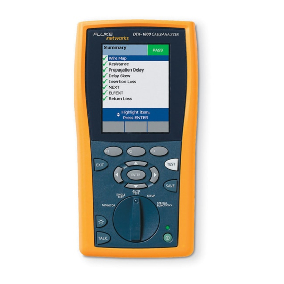
Tutorials on Setup and Test Procedures Certifying Twisted Pair Cabling Step 4: Viewing the Autotest Results The Summary screen, shown in Figure 2-6, tells you if the Autotest Summary test results met the selected test limit. This screen also Screen shows a status for each measurement: : PASS : FAIL... -
Page 66: Step 5: Saving The Results
DTX Series CableAnalyzer Technical Reference Handbook Step 5: Saving the Results Certifying Fiber Cabling 5-1 Press This section familiarizes you with the optional DTX-MFM2, DTX-GFM2, and DTX-SFM2 fiber modules by guiding you 5-2 Use the text editing screen to enter a name for the through the following tasks: results. - Page 67 Tutorials on Setup and Test Procedures Certifying Fiber Cabling amd46f.eps Tester and smart remote with fiber modules. Use Two mandrels. Recommended when testing multimode fiber with DTX-MFM2 modules. See page 7-11. DTX-MFM2 modules for testing multimode fiber. Use DTX-GFM2 modules for testing multimode fiber for Fiber cleaning supplies Gigabit Ethernet applications.
-
Page 68: Step 1: Installing The Fiber Modules
DTX Series CableAnalyzer Technical Reference Handbook Step 1: Installing the Fiber Modules Caution 1-1 Turn off the tester and smart remote. Leave the module bay covers in place when the fiber modules are not installed. 1-2 Remove the cover from the back of each unit and install a DTX-MFM2, DTX-GFM2, or DTX-SFM2 module in each Step 2: Checking the Battery Status and Verifying unit, as shown in Figure 2-8. -
Page 69: Step 3: Selecting A Fiber Type And Test Limit
Tutorials on Setup and Test Procedures Certifying Fiber Cabling 3-3 On the Fiber menu use to select Fiber SC to SC reference test cord Type. Fiber types are organized in groups: • Generic: Generic types of fiber • Custom: Fiber types entered by a DTX user •... -
Page 70: Step 4: Configuring The Fiber Test
DTX Series CableAnalyzer Technical Reference Handbook Step 4: Configuring the Fiber Test Step 5: Setting the Reference 5-1 Clean the connectors on the tester and the two 4-1 Turn the rotary switch to SETUP. reference test cords. 4-2 Use to highlight Fiber; then press 5-2 Turn the rotary switch to SPECIAL FUNCTIONS. - Page 71 Tutorials on Setup and Test Procedures Certifying Fiber Cabling amd145f.eps Figure 2-10. Smart Remote Mode Reference Connections (Method B) 2-17...
-
Page 72: Step 6: Running The Test
DTX Series CableAnalyzer Technical Reference Handbook Step 6: Running the Test 6-3 Turn the rotary switch to AUTOTEST. If a copper adapter is attached, verify that the media type is set to Fiber. 6-1 Clean the connectors on the cabling to be tested. Press Change Media to change it if necessary. -
Page 73: Step 7: Viewing The Results
Tutorials on Setup and Test Procedures Certifying Fiber Cabling Step 7: Viewing the Results This concludes the tutorial on testing fiber cabling. For more information on testing fiber cabling, see Chapter 6. The Summary screen, shown in Figure 2-12, tells you if the test results met the selected test limit. -
Page 74: Using The Auto Increment And Sequential Cable Id Features
DTX Series CableAnalyzer Technical Reference Handbook Using the Auto Increment and Letters increment through the alphabet shown on the text editing screen: Sequential Cable ID Features 1A, 1B, 1C…1Y, 1Z, 1Ç…1Û, 1Ü, 1A The auto increment and sequential ID features generate To use the auto increment ID feature: cable IDs automatically. -
Page 75: Creating A List Of Sequential Ids
Tutorials on Setup and Test Procedures Using the Auto Increment and Sequential Cable ID Features Creating a List of Sequential IDs These IDs produce the following ID list: The tester includes templates for creating a list of ROOM A DROP#1 sequential IDs. - Page 76 DTX Series CableAnalyzer Technical Reference Handbook to highlight Auto Sequence, then press 13 Press to leave the sample list. If the tester shows an error message, check your Start to highlight Template, then press and Stop IDs for the problems listed below. 14 Press when you are done setting up the list.
-
Page 77: About Ansi/Tia/Eia-606-A Cable Ids
Tutorials on Setup and Test Procedures Using the Auto Increment and Sequential Cable ID Features To use an ID from the auto sequence list: Horizontal Link Identifier Horizontal links run between telecommunications closets Verify that the Cable ID Source in SETUP is set to Auto and work areas. - Page 78 DTX Series CableAnalyzer Technical Reference Handbook Campus Cable Identifier Campus cables are backbone cables that run between buildings. Format: [b1-f s1]/[b2-fs2]-n.d Example: LBRY-01A/AUD-01A-5.16 The cable tested is in the backbone cable that runs between the library (LBRY), floor 1, telecom room A and the auditorium (AUD), floor 1, telecom room A.
-
Page 79: Certifying Twisted Pair Cabling
Chapter 3 Certifying Twisted Pair Cabling Setting the Reference To set the reference: Attach permanent link and channel adapters and make The reference procedure sets a baseline for insertion loss, the connections shown in Figure 3-1. ELFEXT, and dc resistance measurements. Run the tester’s reference procedure at the following times: Turn the rotary switch to SPECIAL FUNCTIONS and turn •... -
Page 80: Testing Twisted Pair Patch Cords
Permanent link Patch cord testing requires the optional DTX-PCU6S Patch adapter Cord Adapter Set. Contact Fluke Networks or visit the Fluke Networks website for more information. Channel adapter PASS... -
Page 81: Twisted Pair Test Settings
Certifying Twisted Pair Cabling Twisted Pair Test Settings Twisted Pair Test Settings To access the settings, turn the rotary switch to SETUP, use to highlight Twisted Pair; then press Table 3-1 describes the settings that apply to twisted pair cabling tests. Table 3-1. -
Page 82: Dtx Series Cableanalyzer Technical Reference Handbook
DTX Series CableAnalyzer Technical Reference Handbook Table 3-1. Twisted Pair Test Settings (cont.) Setting Description SETUP > Twisted The Outlet Configuration setting determines which cable pairs are tested and which pair numbers are Pair > Outlet assigned to the pairs. To see the wire map for a configuration, press Sample from the Outlet Configuration Configuration screen. - Page 83 You should also set the reference every 30 days. See “Setting the Reference” on page 3-1. SETUP > Instrument Cable ID Source, Current Folder, Result Storage Location (DTX-1800, DTX-1200), Operator, Site, Settings Company, and Auto Save Results setting. See “Preparing to Save Tests” on page 2-1 and Settings for saving tests “Automatically Saving Results”...
-
Page 84: Autotest On Twisted Pair Cabling
DTX Series CableAnalyzer Technical Reference Handbook Autotest on Twisted Pair Cabling To run the Autotest on twisted pair cabling: Verify that the settings listed in Table 3-1are Figure 3-2 shows the equipment needed for certifying appropriate. twisted pair cabling. Attach adapters appropriate for the job to the tester and the smart remote. - Page 85 Certifying Twisted Pair Cabling Autotest on Twisted Pair Cabling Horizontal cabling Optional consolidation point Work area Patch panel Wall outlet Start permanent permanent link link PASS TEST FAIL TALK TONE Tester with permanent Smart remote with LOW BATTERY link adapter permanent link adapter EXIT TEST...
- Page 86 DTX Series CableAnalyzer Technical Reference Handbook Horizontal cabling Hub or switch Optional consolidation point Patch cord from hub or Work area switch Patch Wall panels outlet Start Patch channel cord channel from PC PASS TEST FAIL TALK TONE LOW BATTERY Tester with Smart remote with EXIT...
-
Page 87: Twisted Pair Autotest Results
Certifying Twisted Pair Cabling Twisted Pair Autotest Results • Twisted Pair Autotest Results Return loss • ACR (attenuation to crosstalk ratio) and ACR at the The tests listed below apply to twisted pair cabling. smart remote Note • PSACR (power-sum attenuation to crosstalk ratio) and The Autotest runs some or all of the tests listed PSACR at the smart remote below, depending on the selected test limit. - Page 88 DTX Series CableAnalyzer Technical Reference Handbook PASS: All parameters are within limits. FAIL: One or more parameters exceeds the limit. PASS*/FAIL*: One or more parameters are within the tester’s accuracy uncertainty range, and the “*” notation is required by the selected test standard. See “PASS*/FAIL* Results” on page 3- Press to scroll the screen.
-
Page 89: Automatic Diagnostics
Certifying Twisted Pair Cabling Twisted Pair Autotest Results Automatic Diagnostics to solve the problem. A failed test may produce more than ADBC one diagnostic screen. In this case, press If an Autotest fails, press Fault Info for diagnostic to see additional screens. information about the failure. -
Page 90: Pass*/Fail* Results
DTX Series CableAnalyzer Technical Reference Handbook PASS*/FAIL* Results passing and failing results are marked with blue and red asterisks, respectively. A result marked with an asterisk means that measurements A PASS* may be considered a passing result. are in the tester’s accuracy uncertainty range (Figure 3-7) and the “*”... -
Page 91: Wire Map
Certifying Twisted Pair Cabling Twisted Pair Autotest Results Wire Map Tip: The wire map test in Single Test mode features a scanning function that runs the wire map test Wire map results show the connections between the main continuously. This function is helpful for locating and remote testers. - Page 92 DTX Series CableAnalyzer Technical Reference Handbook amd82i.bmp amd83i.bmp amd84i.bmp Split pair Reversed pair Crossed pairs A wire in the 3,6 pair is crossed with a wire Wires 1 and 2 are crossed. Pairs 1,2 and 3,6 are crossed. in the 4,5 pair. Figure 3-8.
-
Page 93: Resistance
Certifying Twisted Pair Cabling Twisted Pair Autotest Results Resistance Resistance results show the dc loop resistance for each cable pair. The smart remote shorts the end of each pair to create the loops. A pair’s resistance depends on the integrity of the contacts in the connector, the length of the pair, and its wire gauge. -
Page 94: Characteristic Impedance
DTX Series CableAnalyzer Technical Reference Handbook Characteristic Impedance Note Most test limits do not require the characteristic impedance measurement. Characteristic impedance is not displayed for these limits. Impedance measurements require a cable at least 13 ft (4 m) long. The tester shows Unknown for cables shorter than this. -
Page 95: Length
Certifying Twisted Pair Cabling Twisted Pair Autotest Results Length Length results show the length of each cable pair. The PASS/FAIL result is assigned based on the shortest measured length. The lengths of the other pairs are shown for informational purposes. A 2 % to 5 % difference in measured length among cable pairs is normal because of the following: •... -
Page 96: Propagation Delay And Delay Skew
DTX Series CableAnalyzer Technical Reference Handbook Propagation Delay and Delay Skew Delay skews are the differences in propagation delays between the shortest delay and the delays of the other Propagation delay is the time taken for a test pulse to travel cable pairs. -
Page 97: Insertion Loss
Certifying Twisted Pair Cabling Twisted Pair Autotest Results Insertion Loss At higher frequencies, signals tend to travel only near the surface of a conductor. This “skin effect”, along with the Note cabling’s inductance and capacitance, cause insertion loss to Insertion loss is also known as attenuation. increase with frequency. - Page 98 DTX Series CableAnalyzer Technical Reference Handbook The overall insertion loss result. “PASS*/FAIL* Results” on page 3-12 describes results marked with an asterisk. Horizontal and vertical magnification levels for the plot. To change the magnification, press Change To Zoom; then to zoom horizontally or vertically. The limit line (in red) for insertion loss.
-
Page 99: Next (Near-End Crosstalk)
Certifying Twisted Pair Cabling Twisted Pair Autotest Results NEXT (Near-End Crosstalk) For NEXT failures, the tester's diagnostic screens ( Fault Info) may show more than one possible cause for the NEXT results show the crosstalk attenuation between cable failure. In this case, you can use the HDTDX analyzer results pairs. - Page 100 DTX Series CableAnalyzer Technical Reference Handbook The location of the NEXT results. Press to switch between the tester and smart remote. The overall NEXT result. “PASS*/FAIL* Results” on page 3-12 describes results marked with an asterisk. Horizontal and vertical magnification levels for the plot. To change the magnification, press Change To Zoom;...
-
Page 101: Acr (Attenuation To Crosstalk Ratio)
Certifying Twisted Pair Cabling Twisted Pair Autotest Results ACR (Attenuation to Crosstalk Ratio) attenuation (insertion loss). Higher ACR values mean received signals are much larger than crosstalk signals. ACR is like a signal-to-noise ratio. ACR values indicate how Higher ACR values correspond to better cabling the amplitude of signals received from a far-end transmitter performance. - Page 102 DTX Series CableAnalyzer Technical Reference Handbook The location of the ACR results. Press to switch between the tester and smart remote. The overall ACR result. “PASS*/FAIL* Results” on page 3-12 describes results marked with an asterisk. Horizontal and vertical magnification levels for the plot. To change the magnification, press Change To Zoom;...
-
Page 103: Return Loss
Certifying Twisted Pair Cabling Twisted Pair Autotest Results Return Loss A return loss plot indicates how well a cable’s impedance matches its rated impedance over a range of frequencies. Return loss is the difference between the power of a Figure 3-19 describes the return loss plot. transmitted signal and the power of the signals reflected For return loss failures, the testers diagnostic screens ( back. - Page 104 DTX Series CableAnalyzer Technical Reference Handbook The location of the return loss results. Press to switch between the tester and smart remote. The overall return loss result. “PASS*/FAIL* Results” on page 3-12 describes results marked with an asterisk. Horizontal and vertical magnification levels for the plot. To change the magnification, press Change To Zoom;...
-
Page 105: Psnext (Power Sum Near End Crosstalk) Test
Certifying Twisted Pair Cabling Twisted Pair Autotest Results PSNEXT (Power Sum Near End Crosstalk) Test PSACR (Power Sum Attenuation to Crosstalk Ratio) Test PSNEXT results show how much each cable pair is affected by the combined crosstalk from the other pairs. PSNEXT is PSACR values indicate how the amplitude of signals the difference (in dB) between the test signal and the received from a far-end transmitter compares to the... -
Page 106: Elfext (Equal Level Far-End Crosstalk) Test
DTX Series CableAnalyzer Technical Reference Handbook ELFEXT (Equal Level Far-End Crosstalk) Test Like ACR, ELFEXT represents a signal-to-noise ratio for the cabling. Higher ELFEXT values mean that data signals While NEXT is measured at the same end as the signal received at the far end of the cabling are much larger than source, FEXT (far-end crosstalk) is measured at the far end. - Page 107 Certifying Twisted Pair Cabling Twisted Pair Autotest Results Signal source Crosstalk farther from the input Crosstalk near the input Far-end crosstalk amd94f.eps Figure 3-20. Far-End Crosstalk (FEXT) 3-29...
- Page 108 DTX Series CableAnalyzer Technical Reference Handbook The location of the ELFEXT results. Press to switch between the tester and smart remote. The overall ELFEXT result. “PASS*/FAIL* Results” on page 3-12 describes results marked with an asterisk. Horizontal and vertical magnification levels for the plot. To change the magnification, press Change To Zoom;...
-
Page 109: Pselfext Test
Certifying Twisted Pair Cabling Running Single Tests PSELFEXT Test Running Single Tests PSELFEXT results show how much the far end of each cable The tester’s single test mode (SINGLE TEST on the rotary pair is affected by the combined far-end crosstalk from the switch) lets you run individual tests for isolating cabling other pairs. - Page 110 DTX Series CableAnalyzer Technical Reference Handbook Table 3-2. Smart Remote Requirements for Twisted Pair Single Tests Test Smart Remote Requirements* HDTDX analyzer Recommended. Without a smart remote, results for short cables may be unreliable. HDTDR analyzer Optional. Without a smart remote, the plot shows large reflections at the end of the cabling. Recommended.
-
Page 111: Monitoring Impulse Noise
Certifying Twisted Pair Cabling Monitoring Impulse Noise Monitoring Impulse Noise Noise distorts the shape of digital signals, as shown in Figure 3-22. Too much noise can cause transmission errors, Impulse noise is electrical noise generated by fluorescent resulting in poor network performance. lights, electric motors, electric heaters and air conditioners, The impulse noise test lets you monitor noise on inactive photocopiers, refrigerators, microwave ovens, and other... - Page 112 Stop; then use to change the value. Press resume testing. Tip: Fluke Networks recommends a noise threshold of 30 mV with an average pulse rate below 0.01/sec for testing 1000BASE-T (Gigabit Ethernet) cabling. To stop the test at any time, press...
- Page 113 Certifying Twisted Pair Cabling Monitoring Impulse Noise The average number of noise hits per second. The highest number of noise hits per second since the start of the test. The time shows when the peak was recorded. The minimum level of noise considered to be a noise hit. To change the threshold, press Stop;...
-
Page 114: Using The Tone Generator
Note ™ a tone probe such as a Fluke Networks IntelliTone probe. The toner's signal may not be detectable along The tone probe converts the toner’s signal to audible tones... - Page 115 Certifying Twisted Pair Cabling Using the Tone Generator Patch panel Tone probe, such as Volume control the Fluke Networks PASS TEST IntelliTone probe FAIL TALK TONE LOW BATTERY Tester or smart remote Press to start the toner TEST TALK amd96f.eps Figure 3-24.
- Page 116 DTX Series CableAnalyzer Technical Reference Handbook 3-38...
-
Page 117: Testing Twisted Pair Through A Poe Device
Chapter 4 Testing Twisted Pair Through a PoE Device Autotest Through a PoE Device The AC wire map test lets you test links connected through midspan PoE (Power over Ethernet) devices. When you To test cabling through a PoE device, enable the AC Wire enable this test, the tester uses AC signals instead of DC Map test, connect to the cabling as shown in Figure 4-1 for signals to test the wire map between the main and remote... - Page 118 DTX Series CableAnalyzer Technical Reference Handbook Horizontal cabling Optional consolidation Patch panel point Work area Midspan PoE Wall device outlet Start permanent permanent link link PASS TEST FAIL TALK TONE Smart remote with Tester with permanent LOW BATTERY permanent link adapter link adapter EXIT TEST...
- Page 119 Testing Twisted Pair Through a PoE Device Autotest Through a PoE Device amd58f.eps Figure 4-2. Testing a Channel Through a PoE Device...
-
Page 120: Ac Wire Map Results
DTX Series CableAnalyzer Technical Reference Handbook AC Wire Map Results When the tester detects multiple wire map faults, it may not display the wire map screen, but may show a diagnostics AC wire map results are similar to the wire map results screen instead. - Page 121 Testing Twisted Pair Through a PoE Device AC Wire Map Results amd52.bmp amd50.bmp amd45.bmp Open on pair 1,2. The open is 21.7 m Short between pairs 1,2 and 3,6. The Split pair on pairs 1,2 and 3,6. The from the tester and 61.4 m from the short is 1.7 m from the tester.
- Page 122 DTX Series CableAnalyzer Technical Reference Handbook The tester detected one or more wire map faults on pairs 1,2 The tester detected multiple, complex faults on the cabling. and 3,6 about 4 ft from the tester. The distance to faults may not be given for some types of complex faults.
-
Page 123: Running The Ac Wire Map Test As A Single Test
Testing Twisted Pair Through a PoE Device Running the AC Wire Map Test as a Single Test Running the AC Wire Map Test as a Single Test To run the AC Wire Map test as a single test, enable the test in SETUP, turn the rotary switch to SINGLE TEST;... - Page 124 DTX Series CableAnalyzer Technical Reference Handbook...
-
Page 125: Certifying Coaxial Cabling
Chapter 5 Certifying Coaxial Cabling Certifying coaxial cabling requires the optional DTX-COAX Note coaxial adapters. Turn on the tester and let it sit for 1 minute before setting the reference. Set the reference only after Setting the Reference the testers have reached an ambient temperature °... -
Page 126: Coaxial Test Settings
DTX Series CableAnalyzer Technical Reference Handbook Coaxial Test Settings Table 5-1 describes the settings that apply to coaxial cabling tests. To access the settings, turn the rotary switch to SETUP, use to highlight Coax; then press PASS TEST FAIL TALK TONE LOW BATTERY EXIT... - Page 127 Certifying Coaxial Cabling Coaxial Test Settings Table 5-1. Coaxial Cable Test Settings Setting Description SETUP > Coaxial Select the appropriate test limit for the job. > Test Limit SETUP > Coaxial Select a cable type appropriate for the type you will test. >...
- Page 128 Set Reference You should also set the reference every 30 days. See “Setting the Reference” on page 5-1. Cable ID Source, Current Folder, Result Storage Location (DTX-1800, DTX-1200), Operator, Site, Settings for saving tests and Company. See “Preparing to Save Tests” in on page 2-1.
-
Page 129: Autotest On Coaxial Cabling
Certifying Coaxial Cabling Autotest on Coaxial Cabling Autotest on Coaxial Cabling Figure 5-2 shows the equipment needed for certifying coaxial cabling. PASS TEST FAIL TALK TONE LOW BATTERY EXIT TEST ENTER SAVE AUTO TEST SINGLE SETUP TEST SPECIAL MONITOR FUNCTIONS TEST TALK TALK... - Page 130 DTX Series CableAnalyzer Technical Reference Handbook To run the Autotest on coaxial cabling: Press on the tester or smart remote. To stop the test at any time, press Verify that the settings listed in Table 5-1 are The tester shows the Autotest Summary screen when appropriate.
- Page 131 Certifying Coaxial Cabling Autotest on Coaxial Cabling PASS TEST FAIL TALK TONE LOW BATTERY EXIT TEST ENTER SAVE AUTO SINGLE TEST SETUP TEST SPECIAL MONITOR FUNCTIONS TEST TALK TALK amd139.eps Figure 5-3. Coaxial Network Cabling Test Connections...
- Page 132 DTX Series CableAnalyzer Technical Reference Handbook Connection to coaxial cabling Wall outlet Female to female Female to female F-connector adapter F-connector adapter PASS TEST FAIL TALK TONE LOW BATTERY Tester with coaxial Smart remote with EXIT TEST adapter coaxial adapter ENTER SAVE AUTO...
-
Page 133: Coaxial Autotest Results
Certifying Coaxial Cabling Coaxial Autotest Results Coaxial Autotest Results Note The Autotest runs some or all of the tests shown in Figure 5-5 describes the Autotest Summary screen, which Figure 5-5, depending on the selected test limit. lists the tests that apply to coaxial cabling. PASS: All parameters are within limits. -
Page 134: Hdtdr Analyzer
DTX Series CableAnalyzer Technical Reference Handbook HDTDR Analyzer Characteristic impedance is the impedance a cable would have if the cable were infinitely long. Good cabling has ™ The HDTDR (High-Definition Time Domain Reflectometry) relatively constant characteristic impedance throughout the analyzer plots the locations and magnitudes of reflections cable and connectors. -
Page 135: Insertion Loss
Certifying Coaxial Cabling Running Single Tests Insertion Loss Running Single Tests Insertion loss is the loss of signal strength over the cabling. The tester’s single test mode (SINGLE TEST on the rotary Insertion loss is caused by the resistance of the copper wire switch) lets you run individual tests for isolating cabling and connecting hardware and by leakage of electrical failures and quickly testing repairs. - Page 136 DTX Series CableAnalyzer Technical Reference Handbook Table 5-2. Smart Remote Requirements for Coaxial Single Tests Test Smart Remote Requirements* HDTDR analyzer Optional. Without a smart remote, the plot shows large reflections at the end of the cabling. Resistance Smart remote or terminator required for loop resistance measurement. Length Not required.
-
Page 137: Diagnosing Copper Cabling Faults
• information about the location and likely cause of the fault. Keep the tester’s software current. The latest software is available on the Fluke Networks website. See page 13-2 for details on installing updates. • Set the reference for the twisted pair adapters every 30 days. -
Page 138: Common Causes Of Copper Cabling Failures
DTX Series CableAnalyzer Technical Reference Handbook Common Causes of Copper Cabling Failures Table 6-1 describes common causes of test failures on twisted pair and coaxial cabling. Table 6-1. Diagnosing Twisted Pair Test Failures Wire Map: open • Wires connected to wrong pins at connector or punchdown blocks Tip: The wire map test in Single Test mode features a •... - Page 139 Diagnosing Copper Cabling Faults Common Causes of Copper Cabling Failures Table 6-1. Diagnosing Twisted Pair Test Failures (cont.) Wire Map: crossed wires • Wires connected to wrong pins at connector or punchdown block. • Mix of 568A and 568B wiring standards (12 and 36 crossed). •...
- Page 140 DTX Series CableAnalyzer Technical Reference Handbook Table 6-1. Diagnosing Twisted Pair Test Failures (cont.) NEXT, PSNEXT, ELFEXT, PSELFEXT gives FAIL, FAIL*, or PASS* result • Excessive untwisting of pairs at connector Note • Fixing NEXT problems usually corrects ELFEXT Poor quality patch cords problems.
- Page 141 Diagnosing Copper Cabling Faults Common Causes of Copper Cabling Failures Table 6-1. Diagnosing Twisted Pair Test Failures (cont.) NEXT passes, but the plot shows that measurements exceed the limit For ISO/IEC standards, NEXT is not evaluated where insertion loss is less than 4 dB (the 4 dB rule). Return passes, but the plot shows that measurements exceed the limit Return loss is not evaluated where insertion loss is less than 3 dB (the 3 dB rule).
- Page 142 DTX Series CableAnalyzer Technical Reference Handbook Table 6-1. Diagnosing Twisted Pair Test Failures (cont.) Return loss gives FAIL, FAIL*, or PASS* result (cont.) • Mismatches in cable construction (such as cable from different manufacturers) • Water in cable jacket • Cable compression (tight cable ties, pinches, kinks, etc.) •...
- Page 143 Diagnosing Copper Cabling Faults Common Causes of Copper Cabling Failures Table 6-1. Diagnosing Twisted Pair Test Failures (cont.) Characteristic impedance exceeds the limit or an anomaly is detected • Bad connection • Cable compression (tight cable ties, pinches, kinks, etc.) •...
- Page 144 DTX Series CableAnalyzer Technical Reference Handbook Table 6-1. Diagnosing Twisted Pair Test Failures (cont.) Propagation delay or delay skew gives FAIL result • Cable is too long (may need to remove coiled service loops) • Cable uses different insulation materials on different pairs Impulse noise is detected •...
-
Page 145: The Hdtdx Analyzer
Diagnosing Copper Cabling Faults The HDTDX Analyzer The HDTDX Analyzer Turn on the smart remote; then connect the tester and remote to the cabling. ™ The HDTDX (High-Definition Time Domain Crosstalk) analyzer plots the locations and magnitudes of crosstalk on Turn the rotary switch to SINGLE TEST, select HDTDX the cabling under test. - Page 146 DTX Series CableAnalyzer Technical Reference Handbook Magnification level for the plot. Use zoom in or out at the cursor’s location. The distance to the end of the cabling. The cursor and the distance to the cursor from the tester. Use to move the cursor.
-
Page 147: Recognizing Faults On Hdtdx Plots
Diagnosing Copper Cabling Faults The HDTDX Analyzer Recognizing Faults on HDTDX Plots Figure 6-2 shows how some common faults appear on HDTDX plots. Bad section of cable Bad spool of cable Bad patch cord amd98f.eps A bad patch cord about 53 m from the tester. A spool of cable with poor NEXT performance. -
Page 148: The Hdtdr Analyzer
DTX Series CableAnalyzer Technical Reference Handbook The HDTDR Analyzer Turn on the smart remote; then connect the tester and remote to the cabling. ™ The HDTDR (High-Definition Time Domain Reflectometry) analyzer plots the locations and magnitudes of reflections Turn the rotary switch to SINGLE TEST, select HDTDR caused by impedance anomalies. - Page 149 Diagnosing Copper Cabling Faults The HDTDR Analyzer Magnification level for the plot. Use zoom in or out at the cursor’s location. The distance to the end of the cabling. The cursor and the distance to the cursor from the tester. Use to move the cursor.
- Page 150 DTX Series CableAnalyzer Technical Reference Handbook Open Short Bad patch cord Cable section with Cable section with the wrong impedance poor return loss amd100f.eps Figure 6-4. Interpreting HDTDR Plots 6-14...
- Page 151 Diagnosing Copper Cabling Faults The HDTDR Analyzer Open on pair 1,2 near the smart remote. A positive A link with a section of cable that has higher impedance (120 Ω) than the rest of the cable. The bad section starts reflection indicates an increase in impedance.
- Page 152 DTX Series CableAnalyzer Technical Reference Handbook 6-16...
-
Page 153: Certifying Fiber Optic Cabling
Chapter 7 Certifying Fiber Optic Cabling • Overview of Features Interchangeable connector adapters allow reference and test connections that meet ISO standards for most The optional DTX-MFM2, DTX-GFM2, and DTX-SFM2 fiber SFF (small form factor) fiber connectors. modules are used with a DTX Series CableAnalyzer to test •... -
Page 154: Safety Information
DTX Series CableAnalyzer Technical Reference Handbook • Safety Information Never look directly into the visual fault locator output. Momentary exposure to the locator’s Warning: Class 1 and Class 2 Laser output will not damage your eyes; however, direct, long-term exposure is potentially Products hazardous. - Page 155 • Leave the module bay covers in place when the • Use a Fluke Networks FiberInspector Video fiber modules are not installed. Microscope to periodically inspect the fiber • When using the fiber modules, use proper module’s OUTPUT connector for scratches and...
-
Page 156: Installing And Removing Fiber Modules
DTX Series CableAnalyzer Technical Reference Handbook Installing and Removing Fiber Modules Figure 7-1 shows how to install and remove the fiber modules. Caution Leave the module bay covers in place when the modules are not installed. amd34af.eps Figure 7-1. Installing and Removing Fiber Modules... - Page 157 Certifying Fiber Optic Cabling Installing and Removing Fiber Modules Button for activating the visual fault locator (B) and output port (D). See Chapter 8 and “Autotest in Far End Source Mode” on page 7-18. Universal fiber connector (with dust cap) for the visual fault locator output. The connector accepts 2.5 mm ferrules.
-
Page 158: Installing The Connector Adapter
3). Additional adapter styles may be available. Check the • Store the connector adapters for the fiber module Fluke Networks web site for updates. in the canisters provided. • Do not touch the photodiode lens (see Figure 7-4). •... - Page 159 Certifying Fiber Optic Cabling Installing the Connector Adapter amd99f.eps Figure 7-4. Installing the Connector Adapter...
-
Page 160: Verifying Operation
DTX Series CableAnalyzer Technical Reference Handbook Verifying Operation SC to SC reference test cord Clean the tester’s connectors and the connectors on two SC/SC reference test cords. Connect the tester and smart remote together, as shown in Figure 7-5. Turn the rotary switch to SPECIAL FUNCTIONS. PASS TEST FAIL... -
Page 161: Essentials For Reliable Fiber Test Results
Essentials for Reliable Fiber Test Results Essentials for Reliable Fiber Test Results Inspect connectors with a fiber microscope, such as the Fluke Networks FiberInspector Video Microscope To get reliable fiber test results, you must follow proper before making connections. cleaning and referencing procedures and, in some cases, use mandrels during testing. -
Page 162: About Setting The Reference
DTX Series CableAnalyzer Technical Reference Handbook • Connector Ends Anytime the tester warns you that the reference is out of date. Wipe the end of the ferrule with a swab or wipe lightly • moistened with alcohol. Dry with a dry swab or wipe. Anytime you see a negative loss measurement (see page 9-3. -
Page 163: Testing Your Reference Test Cords
Ethernet. To ensure that your measurements are accurate and Caution repeatable, use reference test cords provided by Fluke Networks or cords of the same quality. See "Replacing Fiber Do not use mandrels when testing with the Reference Test Cords" on page 13-7. - Page 164 DTX Series CableAnalyzer Technical Reference Handbook Table 7-1. TIA/EIA-568-B.1 and ISO/IEC TR 14763-3 Mandrel Requirements Fiber core Wraps Around Mandrel Diameter for Mandrel Diameter for 3 mm size Standard Mandrel 250 µm Buffered Fiber (0.12 in) Jacketed Cable 50 µm TIA/EIA-568-B.1 7.1 25 mm (1.0 in) 22 mm (0.9 in)
- Page 165 Certifying Fiber Optic Cabling Essentials for Reliable Fiber Test Results Place top wrap in groove under retainer Wrap 5 times in grooves Right: no bends at retainer Wrong: bends at retainer amd67f.eps Figure 7-6. Wrapping a Reference Test Cord Around a Mandrel 7-13...
-
Page 166: Fiber Test Settings
DTX Series CableAnalyzer Technical Reference Handbook Fiber Test Settings To access the fiber test settings turn the rotary switch to SETUP; then select Fiber. Use to see different tabs. Table 7-2 describes the test settings that apply to fiber cabling. Table 7-2. - Page 167 Certifying Fiber Optic Cabling Fiber Test Settings Table 7-2. Fiber Test Settings (cont.) Setting Description SETUP > Fiber > If the selected limit uses a calculated loss limit, enter the number of adapters and splices that will be Number of Adapters added to the fiber path after the reference is set.
- Page 168 DTX Series CableAnalyzer Technical Reference Handbook amd65f.eps Figure 7-7. Example of How to Determine the Number of Adapters Setting (singlemode example; mandrels not used) 7-16...
- Page 169 Connections screen) TSB-140 reporting requirements. SETUP > Instrument Cable ID Source, Current Folder, Result Storage Location (DTX-1800, DTX-1200), Operator, Site, Settings Company, and Auto Save Results setting. See “Preparing to Save Tests” on page 2-1 and “Automatically Saving Results” on page 1-29.
-
Page 170: About Method B Connections
DTX Series CableAnalyzer Technical Reference Handbook About Method B Connections Autotest in Smart Remote Mode The reference and test connections shown in this manual Use Smart Remote mode to test and certify dual-fiber produce Method B results. Method B results include the loss cabling. - Page 171 Certifying Fiber Optic Cabling Autotest in Smart Remote Mode amd46f.eps Tester and smart remote with fiber modules and Duplex reference test cords. Match the fiber to be tested. Long ends must have SC connectors. For the connector adapters installed. Match connector adapters other connectors, match the connectors in the link.
-
Page 172: Setting The Reference For Smart Remote Mode
DTX Series CableAnalyzer Technical Reference Handbook Setting the Reference for Smart Remote Mode Press Turn on both testers and let them sit for 5 minutes. The View Reference screen shows the reference values Allow additional time if the modules have been stored and the date and time the reference was set. - Page 173 Certifying Fiber Optic Cabling Autotest in Smart Remote Mode amd145f.eps Figure 7-9. Smart Remote Mode Reference Connections (Method B) 7-21...
-
Page 174: Running The Autotest In Smart Remote Mode
DTX Series CableAnalyzer Technical Reference Handbook Running the Autotest in Smart Remote Mode If Open or Unknown appears as the status, try the following: Caution • Verify that all connections are good. If the reference test cords have been disconnected •... - Page 175 Certifying Fiber Optic Cabling Autotest in Smart Remote Mode amd146f.eps Figure 7-10. Smart Remote Mode Test Connections (Method B) 7-23...
-
Page 176: Smart Remote Mode Autotest Results
DTX Series CableAnalyzer Technical Reference Handbook Smart Remote Mode Autotest Results Figure 7-11 describes the Summary screen and loss results screen for an unsaved, single-directional Autotest in Smart The Summary screen appears when the test is finished. To Remote mode. see more detailed results, use to highlight a For bi-directional results in Smart Remote mode, see... - Page 177 Certifying Fiber Optic Cabling Autotest in Smart Remote Mode Note To see the propagation delay, select the length result. The results described here are for an unsaved test. Propagation delay is half the time taken for a signal to Unsaved tests for Smart Remote mode show results travel from the main tester to the remote and back again.
-
Page 178: Autotest In Loopback Mode
DTX Series CableAnalyzer Technical Reference Handbook Autotest in Loopback Mode Use Loopback mode to test spools of cable, segments of uninstalled cable, and patch cords. In this mode, the tester measures loss, length, and propagation delay at two wavelengths in one or both directions. Figure 7-12 shows the equipment required for testing fiber in Loopback mode. - Page 179 Certifying Fiber Optic Cabling Autotest in Loopback Mode amd49f.eps Tester with fiber module and connector adapter Two adapters of the appropriate type installed (match connector adapter to the connectors in Mandrel Recommended when testing multimode fiber the link) with DTX-MFM2 modules. See page 7-11. Memory card (optional) Fiber cleaning supplies AC adapter with line cord (optional)
-
Page 180: Setting The Reference In Loopback Mode
DTX Series CableAnalyzer Technical Reference Handbook Setting the Reference in Loopback Mode Press Turn on the tester and let it sit for 5 minutes. Allow The View Reference screen shows the reference values additional time if the modules have been stored above and the date and time the reference was set. - Page 181 Certifying Fiber Optic Cabling Autotest in Loopback Mode amd147f.eps Figure 7-13. Loopback Mode Reference Connections (Method B) 7-29...
-
Page 182: Running The Autotest In Loopback Mode
DTX Series CableAnalyzer Technical Reference Handbook Running the Autotest in Loopback Mode Connect the tester to the cabling. Figure 7-14 shows connections for Method B. Caution Turn the rotary switch to AUTOTEST. Verify that the If the reference test cords have been disconnected media type is set to Fiber. - Page 183 Certifying Fiber Optic Cabling Autotest in Loopback Mode amd148f.eps Figure 7-14. Loopback Mode Test Connections (Method B) 7-31...
-
Page 184: Loopback Mode Autotest Results
DTX Series CableAnalyzer Technical Reference Handbook Loopback Mode Autotest Results Figure 7-15 describes the Summary screen and loss results screen for a single-directional Autotest in Loopback mode. The Summary screen appears when the test is finished. For bi-directional results in Loopback mode, see To see more detailed results, use to highlight a “Bi-Directional Testing”... - Page 185 Certifying Fiber Optic Cabling Autotest in Loopback Mode The overall result for the test. The measured loss for the fiber. Note Overall results for the fiber (E is PASS, F is FAIL): • If loss is negative, set the reference again and retest Loss (Output ->...
-
Page 186: Autotest In Far End Source Mode
DTX smart remote with a fiber module. TIA-568B Fiber Backbone limit. The tester does not measure length in Far End Source mode. You can also use other sources, such as a Fluke Networks ® SimpliFiber source or LS-1310/1550 laser source. - Page 187 Certifying Fiber Optic Cabling Autotest in Far End Source Mode amd51f.eps Tester and smart remote with fiber modules and Reference test cord. Match the fiber and connectors in the link. connector adapters installed (match connector adapters to the connectors in the link) Mandrel.
-
Page 188: Setting The Reference In Far End Source Mode
DTX Series CableAnalyzer Technical Reference Handbook Setting the Reference in Far End Source Mode Hold down the button on the smart remote’s fiber module for 3 seconds to turn on the output port at Turn on the tester and smart remote and let them sit 850 nm (DTX-MFM2/GFM2) or 1310 nm (DTX-SFM2). - Page 189 Certifying Fiber Optic Cabling Autotest in Far End Source Mode If you do, you must set the reference again to Caution ensure valid measurements. Do not disconnect the reference test cord from the smart remote’s output after setting the reference. amd149b.eps Figure 7-17.
-
Page 190: Running The Autotest In Far End Source Mode
DTX Series CableAnalyzer Technical Reference Handbook Running the Autotest in Far End Source Mode To set the wavelength on a DTX module used as a source, hold down the button on the smart remote’s Caution fiber module for 3 seconds. This turns on the output port at 850 nm (DTX-MFM2/GFM2) or 1310 nm If the reference test cord has been disconnected (DTX-SFM2). - Page 191 Certifying Fiber Optic Cabling Autotest in Far End Source Mode amd150f.eps Figure 7-18. Far End Source Mode Test Connections (Method B) 7-39...
-
Page 192: Far End Source Mode Autotest Results
DTX Series CableAnalyzer Technical Reference Handbook Far End Source Mode Autotest Results To see more detailed results, use to highlight a measurement; then press The Summary screen appears when the test is finished. Figure 7-19 describes the Summary screen loss results screen for an Autotest in Far End Source mode. - Page 193 Certifying Fiber Optic Cabling Autotest in Far End Source Mode Overall results for the fiber: The maximum loss allowed by the selected test limit. The difference between the limit and the measured loss. Loss (Remote -> Main): Overall loss on the fiber Margin is negative if the loss exceeded the limit.
-
Page 194: Bi-Directional Testing
DTX Series CableAnalyzer Technical Reference Handbook Bi-Directional Testing In Smart Remote mode, you save two results, one for each fiber. See the next section. The Bi-Directional setting lets you test cabling in both directions and save the bi-directional test results in Smart Bi-Directional Results for Smart Remote Mode Remote and Loopback modes. - Page 195 Certifying Fiber Optic Cabling Bi-Directional Testing Unsaved results show both the First saved result is Second saved result is input and output fibers the input fiber the output fiber amd127f.eps Figure 7-20. Unsaved and Saved Bi-Directional Results for Smart Remote Mode 7-43...
-
Page 196: Finding Connections With Findfiber
DTX Series CableAnalyzer Technical Reference Handbook Finding Connections with FindFiber ™ The FindFiber function helps you trace connections at patch panels and quickly check fiber continuity. Note The FindFiber function is not available in Far End Source mode. Using FindFiber in Smart Remote Mode Use the FindFiber function in Smart Remote mode to help you determine which fibers go to which connectors at a patch panel. - Page 197 Certifying Fiber Optic Cabling Finding Connections with FindFiber amd53f.eps Tester and smart remote with fiber modules and Reference test cords. Match the fiber to be tested. One end of each must have an SC connector. For the other connector adapters installed. Match connector adapters connectors, match the connectors in the link.
- Page 198 DTX Series CableAnalyzer Technical Reference Handbook To use the FindFiber function in Smart Remote mode: Turn the rotary switch to SETUP; then select Fiber. Select Remote End Setup; then select Smart Remote. Clean all connectors; then make the connections shown in Figure 7-22. Turn the rotary switch to MONITOR;...
- Page 199 Certifying Fiber Optic Cabling Finding Connections with FindFiber amd54f.eps Figure 7-22. Using FindFiber in Smart Remote Mode 7-47...
- Page 200 DTX Series CableAnalyzer Technical Reference Handbook amd105f.eps amd103f.eps amd104f.eps The main tester’s INPUT fiber path is The main tester’s INPUT fiber path is Both fiber paths are complete. not complete. complete. The main tester’s OUTPUT On the remote, the TEST and PASS fiber path is not complete.
-
Page 201: Using Findfiber In Loopback Mode
Certifying Fiber Optic Cabling Finding Connections with FindFiber Using FindFiber in Loopback Mode Clean all connectors; then connect the tester's OUTPUT fiber to one end of the fiber path, as shown in Use FindFiber in Loopback mode to quickly check the Figure 7-25. - Page 202 DTX Series CableAnalyzer Technical Reference Handbook amd56f.eps Figure 7-25. Using FindFiber in Loopback Mode 7-50...
-
Page 203: Using The Power Meter
Certifying Fiber Optic Cabling Using the Power Meter Using the Power Meter The power meter lets you measure the optical power produced by a source such as an optical network interface card or optical test equipment. The tester offers two versions of the power meter function: •... - Page 204 DTX Series CableAnalyzer Technical Reference Handbook To use the power meter in MONITOR mode: Turn the rotary switch to MONITOR; then select Power Meter. Note If you need to save the power reading, use the Press power meter function in the SINGLE TEST mode. Select the appropriate wavelength;...
- Page 205 Certifying Fiber Optic Cabling Using the Power Meter To use the power meter in SINGLE TEST mode: In Smart Remote mode you will save two power meter results, one for each fiber. In the saved results, Input Note Fiber and Output Fiber refer to the fibers connected to Refer to previous sections on the Autotest in Smart the main tester’s input and output ports at the end of Remote, Loopback, or Far End Source modes for...
- Page 206 DTX Series CableAnalyzer Technical Reference Handbook Results for MONITOR mode Unsaved results for SINGLE TEST mode with Smart remote configuration (Input Fiber shown) amd107f.eps amd106f.eps Meters showing the power readings taken at each Meter showing the power reading. The reading updates wavelength.
-
Page 207: Running Single Tests
Power meter measurement Using the Remote Tester with an OptiFiber Tester You can use a DTX Series smart remote with a DTX-MFM2 or DTX-SFM2 fiber module as the remote for a Fluke ™ Networks OptiFiber Certifying OTDR. The DTX remote... - Page 208 DTX Series CableAnalyzer Technical Reference Handbook 7-56...
-
Page 209: Locating Fibers And Faults With The Visual Fault Locator
Chapter 8 Locating Fibers and Faults with the Visual Fault Locator • Visual Fault Locator Applications Reveal problems in connectors. A damaged fiber inside a connector causes a red glow in the connector. The fiber test module includes a visual fault locator that •... -
Page 210: Using The Visual Fault Locator
DTX Series CableAnalyzer Technical Reference Handbook Using the Visual Fault Locator The visual fault locator port accepts connectors with 2.5 mm ferrules (SC, ST, or FC). To connect to other ferrule sizes, use a patch cord with the appropriate connector at one end and a SC, ST, or FC connector at the tester end. - Page 211 Locating Fibers and Faults with the Visual Fault Locator Using the Visual Fault Locator amd23f.eps Figure 8-2. Using the Visual Fault Locator...
- Page 212 DTX Series CableAnalyzer Technical Reference Handbook...
-
Page 213: Diagnosing Fiber Cabling Faults
Chapter 9 Diagnosing Fiber Cabling Faults Common Causes of Failures The table shows results of a survey of 89 contractors and private network owners. The results show what percentage Most problems in fiber links are caused by dirty, scratched, of each group commonly found the faults listed. or damaged connectors, as shown in Table 9-1. -
Page 214: Diagnosing Failures
The tester’s VFL can reveal damaged connectors and other faults. See Chapter 7 for details. ™ An OTDR, such as the Fluke Networks OF-500 OptiFiber Certifying OTDR, can help you locate faults not revealed with the VFL. - Page 215 Diagnosing Fiber Cabling Faults Diagnosing Failures Table 9-2. Diagnosing Fiber Test Failures (cont.) Loss is negative. • The fiber ends were dirty during referencing. • The connections to the tester were disturbed after referencing. • There was a kink in a reference test cord during referencing. •...
- Page 216 DTX Series CableAnalyzer Technical Reference Handbook Table 9-2. Diagnosing Fiber Test Failures (cont.) Power meter measurement is too low • Fiber endface is dirty or damaged. • Reference test cord not connected to tester’s INPUT port, or a connection is loose. •...
-
Page 217: Verifying Network Service
Ping IP addresses Software Requirements • Monitor network traffic for utilization, collisions, The following software supports the DTX-NSM module. errors, and broadcast packets Software upgrades are available on the Fluke Networks • Blink a port's activity LED website. • ™... -
Page 218: Installing And Removing The Network Module And Optional Sfp Module
DTX Series CableAnalyzer Technical Reference Handbook Installing and Removing the Network Module and Optional SFP Module See Figure 10-2. Install the network module only in the main tester. Install an optional SFP (small form pluggable) module to test fiber links. Caution Leave the module bay cover in place when a module is not installed. - Page 219 Verifying Network Service Installing and Removing the Network Module and Optional SFP Module amd39f.eps Figure 10-2. Installing and Removing the Network and SFP Modules 10-3...
-
Page 220: Verifying Network Connectivity
DTX Series CableAnalyzer Technical Reference Handbook Verifying Network Connectivity Network Connectivity Test Settings The tester needs various addresses to test a network The network connectivity test lets you verify that a twisted connection, as described in Table 10-1.To access these pair or fiber link is connected to a network. -
Page 221: Entering Ping Addresses
Verifying Network Service Verifying Network Connectivity Entering Ping Addresses Turn the rotary switch to SETUP; then select Network Settings. You can use LinkWare software to create and download ping addresses to the tester, or you can enter and edit Select Target Addresses; then do one of the following: addresses directly on the tester. -
Page 222: Running The Connectivity Test
DTX Series CableAnalyzer Technical Reference Handbook Running the Connectivity Test Saving Connectivity Results To test for network connectivity: You can save the network connectivity results in a separate record or with an existing cable test record. Note To save the results in a separate record: The network connectivity test will not run on links with ground loops, analog telephone voltages, Run the network connectivity test, then press... - Page 223 Verifying Network Service Verifying Network Connectivity amd17f.eps Figure 10-3. Network Test Connections 10-7...
- Page 224 DTX Series CableAnalyzer Technical Reference Handbook Speeds supported by the switch or hub: 10 Mbit, 100 Mbit, 1000 Mbit. The current speed is green. Arrows show the connection's duplex configuration: PoE shows if the device appears to support Power over Ethernet. The tester requests power from suspected PoE devices.
- Page 225 Verifying Network Service Verifying Network Connectivity The checkmarks and Xs indicate how many replies the Select Negotiation Details to see details. See Figure 10-5. tester received to its three pings: On the Negotiation Details screen, Yes for Pin Reversal indicates a reversed pair on the link, (such as wires 1 and 2 crossed).
- Page 226 DTX Series CableAnalyzer Technical Reference Handbook The speed negotiated for the connection. The connection's duplex configuration: • Half Duplex: data travels in one direction at a time. • Full Duplex: data travels in both directions at the same time (as with Gigabit Ethernet).
-
Page 227: Pinging Network Devices
Verifying Network Service Pinging Network Devices Pinging Network Devices Do one of the following: • The ping test verifies connectivity to devices on the To ping one device, highlight the device; then press network. • To ping a network device: To ping all devices in the list, press Ping All. - Page 228 DTX Series CableAnalyzer Technical Reference Handbook The name and IP address of the device that was pinged. Number of pings sent and received. The minimum, average, and maximum times taken for the ping requests to travel to the target address and back to the tester (Round Trip Return Time).
-
Page 229: Monitoring Network Traffic
Verifying Network Service Monitoring Network Traffic Monitoring Network Traffic The traffic monitor lets you identify active cables and check a network's basic health. Note Traffic monitor results cannot be saved. To monitor network traffic: Turn on the tester; then connect to the network as shown on page 10-7. - Page 230 DTX Series CableAnalyzer Technical Reference Handbook The time the test has been running. Traffic characteristics for the last 1 second, and the average and peak values since the test began: • Utilization: Percentage of the network’s bandwidth used. This indicates the traffic density on the network.
-
Page 231: Blinking A Port Light
This function generates a link pulse on connections at a patch panel. This function requires one or more optional Fluke Networks LinkRunner ™ Cable ID pairs 12 and 36 to blink the port's activity LED. - Page 232 DTX Series CableAnalyzer Technical Reference Handbook amd20f.eps Figure 10-8. Identifying Links with Optional LinkRunner Cable ID Locators 10-16...
-
Page 233: Diagnosing Low-Level Network Problems
Verifying Network Service Diagnosing Low-Level Network Problems Diagnosing Low-Level Network are usually addressed by a network technician or administrator using a network tester or analyzer. Problems Table 10-2 lists common causes of symptoms you can detect The DTX-NSM module helps you troubleshoot links and with the DTX-NSM module. -
Page 234: Dtx Series Cableanalyzer Technical Reference Handbook
DTX Series CableAnalyzer Technical Reference Handbook Table 10-2. Diagnosing Low-Level Network Problems (cont.) Wire pairs 12 and 36 are reversed • Mix of 568A and 568B wiring standards. • Crossover cables used where not needed. They are typically used only between two switches or hubs. •... - Page 235 Verifying Network Service Diagnosing Low-Level Network Problems Table 10-2. Diagnosing Low-Level Network Problems (cont.) Collision rate averaging above 5 % • Duplex mismatch on the network. • Too many stations within the collision domain. • Faulty hub, switch, NIC, or other device. •...
- Page 236 DTX Series CableAnalyzer Technical Reference Handbook 10-20...
-
Page 237: Custom Test Settings
Chapter 11 Custom Test Settings Creating a Custom Twisted Pair Cable You can customize the following test settings: • Type Twisted pair cable types • Fiber optic cable types You can create up to nine custom twisted pair cable types. •... -
Page 238: Creating A Custom Twisted Pair Test Limit
DTX Series CableAnalyzer Technical Reference Handbook Creating a Custom Twisted Pair Test Limit On the Custom screen, select Name; then use the text editing screen to enter a name for your custom cable You can create up to nine custom twisted pair test limits. A type. -
Page 239: Creating A Custom Fiber Type
Custom Test Settings Creating a Custom Fiber Type To create a custom twisted pair limit: Creating a Custom Fiber Type Turn the rotary switch to SETUP; then select Twisted You can create up to nine custom fiber types. A custom Pair. -
Page 240: Creating A Custom Fiber Limit
DTX Series CableAnalyzer Technical Reference Handbook To change the index of refraction (n) for your custom On the Custom screen, select Name; then use the text fiber, select n for a wavelength; then use the editing editing screen to enter a name for your custom fiber screen to enter a value for n. -
Page 241: Creating A Custom Outlet Configuration
Custom Test Settings Creating a Custom Outlet Configuration Creating a Custom Outlet Configuration If the baseline configuration has additional wire pairs, to move among the tabs. You can create up to nine custom outlet configurations. A custom outlet configuration includes the following settings: From the Custom screen, press when you are done •... -
Page 242: Editing Custom Settings
DTX Series CableAnalyzer Technical Reference Handbook Editing Custom Settings Deleting Custom Settings The editing function lets you change values in existing To delete a custom cable, fiber type, test limit, or outlet custom settings. configuration: To edit an existing custom cable, fiber type, test limit, or Turn the rotary switch to SETUP;... -
Page 243: Changing The Nvp
Custom Test Settings Changing the NVP Changing the NVP Do one of the following: The tester uses an NVP value (nominal velocity of To change the NVP for the selected cable type, select propagation) and the signal delay through cable to NVP on the Twisted Pair or Coax menu. -
Page 244: Resetting The Nvp To The Default Value
DTX Series CableAnalyzer Technical Reference Handbook Select Twisted Pair or Coax. Resetting the NVP to the Default Value You can reset the NVP to the default value defined by the Do one of the following: selected cable type by re-selecting the cable type in SETUP. To change the NVP for the selected cable type, select To reset the NVP to the default value: NVP on the Twisted Pair or Coax menu. -
Page 245: Memory Functions
Or, press Memory from the main Autotest screen. The DTX-1800 and DTX-1200 can store up to 500 Cat 6 Figure 12-1 describes the memory status screen. Autotest results, including graphical data, on a 16 MB removable memory card. - Page 246 DTX Series CableAnalyzer Technical Reference Handbook The memory status currently displayed. is shown for internal memory. is shown for the memory card (DTX-1800, DTX-1200) DTX-1800/DTX-1200: Press to switch between the memory card and internal memory status. The bar graph shows the space used in the current memory destination.
-
Page 247: Setting The Storage Location (Dtx-1800, Dtx-1200)
When Auto Save Results is set to Yes, the tester automatically saves Autotests using the next ID available To set the destination for saved results on a DTX-1800 or from the Cable ID Source. The main Autotest screen shows DTX-1200 tester: the next ID. -
Page 248: Working With Folders
Instrument Settings; then press To create a new folder: Turn the rotary switch to SETUP. DTX-1800, DTX1200: Verify that the Result Storage Location shows the correct location. Change the to highlight Instrument Settings; then location if necessary. press... -
Page 249: Deleting Folders
Memory Functions Working with Folders Deleting Folders To delete a folder and all the results it contains: Turn the rotary switch to SPECIAL FUNCTIONS. to highlight View/Delete Results; then press If necessary, press Change Folder to find the folder you want to delete. Press Delete. -
Page 250: Viewing And Managing Saved Results
DTX Series CableAnalyzer Technical Reference Handbook Viewing and Managing Saved Results Figure 12-2 describes the View Results screen. To view and manage saved results, turn the rotary switch to SPECIAL FUNCTIONS, use to highlight View/Delete Results; then press Sorting order of the list of results. For example, ID means the list is sorted by cable IDs in ascending order. -
Page 251: Moving Or Copying Results To A Memory Card (Dtx-1800, Dtx-1200)
Memory Functions Viewing and Managing Saved Results Moving or Copying Results to a Memory Card (DTX- Deleting Results 1800, DTX-1200) To delete results: To move or copy all results from internal memory to the Turn the rotary switch to SPECIAL FUNCTIONS. memory card: to highlight View/Delete Results;... -
Page 252: Renaming Results
DTX Series CableAnalyzer Technical Reference Handbook Renaming Results The default order is descending by date. The sorting order reverts to the default when you turn off the tester. To rename saved results: On the View Results select the result you want to rename. -
Page 253: Formatting A Memory Card (Dtx-1800, Dtx-1200) Or Internal Memory
Memory Functions Formatting a Memory Card (DTX-1800, DTX-1200) or Internal Memory Formatting a Memory Card (DTX-1800, You can also format a memory card or internal memory in SPECIAL FUNCTIONS mode: DTX-1200) or Internal Memory Turn the rotary switch to SPECIAL FUNCTIONS. -
Page 254: Uploading Results To A Pc
Install the latest version of LinkWare software on your Turn on the tester. Connect the tester to the PC with the USB cable included or the DTX serial cable available from Fluke Networks. Insert the memory card containing results into the PC’s memory card reader. -
Page 255: Maintenance And Specifications
² Use only specified replacement parts for user- tester with a different remote. replaceable items. See “Setting the Reference” on pages 3-1 for twisted pair ² Use only Fluke Networks authorized service cable and 5-1 for coaxial cable. centers. 13-1... -
Page 256: Factory Calibration
Fluke Networks website, or contact Fluke Networks to To get a software update, download the update from the get the update by other means. Save the file to your Fluke Networks website or contact Fluke Networks to get hard drive. the update by other means. - Page 257 The DTX serial cable connects a PC’s DB-9 RS-232 serial port to the miniature RS-232 serial port on the DTX-1800 and DTX-1200 testers. This cable is included with the DTX-1800 and is available from Fluke Networks. Table 13-4 on page 13-38 shows the pin connections for this cable.
- Page 258 DTX Series CableAnalyzer Technical Reference Handbook Updating with Another Tester You can update a tester’s software using another tester that is already updated. Use link interface adapters to connect an updated tester or smart remote to a tester or smart remote that needs updating (Figure 13-2).
-
Page 259: Cleaning
Updating the Limits or Cable Types Database You can update the tester’s software using a memory card Fluke Networks may release a test limits or cable types that contains the software update file. database that is not part of a software update. To install a... -
Page 260: Retraining The Battery Gauge
Battery Status. Verify that both the main and the battery pack. If the internal lithium battery fails, send remote battery gauges are shown. If the remote gauge the tester to a Fluke Networks service center for a is missing, check the connections between the two replacement. -
Page 261: Fiber Module Maintenance
Choose replacement reference test cords that meet the If Table 13-1 does not help you solve a problem with the following requirements: tester, contact Fluke Networks for additional help. See page • Core and cladding size: match the fiber to be tested 1-2 for contact information. - Page 262 OK. If the tester does not recover, press and hold until the tester turns off. If the error recurs, update the tester's software. If the tester already has the latest software, contact Fluke Networks for assistance. The tester will not turn on, even with the ac adapter connected.
- Page 263 The reference test cords and adapters are good, but the reference power level is too low. Clean the tester’s input and output connectors and use a fiber microscope to inspect the endfaces. If an endface is damaged, contact Fluke Networks for service information. A fiber test produces a negative loss reading.
-
Page 264: Options And Accessories
DTX-PLA002S Universal Permanent Link Adapters, Cat 6A, set of 2 DSP-PMxx Personality modules for IDC and legacy cabling systems Many models are available. Contact Fluke Networks or visit the Fluke Networks website for details. DTX-CHA011 Siemon Tera Channel Adapter 13-10... - Page 265 Nexans GG45 Permanent Link Adapter DTX-GG45 Nexans GG45 adapter kit DTX-PCU6S Patch Cord Adapter Kit DTX-10GKIT Alien Crosstalk Analyzer Kit for the DTX-1800 DTX-COAX DTX-COAX Coaxial Adapter Kit DTX-NSM DTX-NSM Network Service Module DTX-MFM2 DTX-MFM2 Multimode Fiber Module, 850 nm/1300 nm...
- Page 266 DTX Series CableAnalyzer Technical Reference Handbook Table 13-2. Options and Accessories (cont.) Option or Accessory Fluke Networks Model Number DTX-FTK DTX-FTK Fiber Test Kit Fiber optic meter module and 850 nm/1300 nm SimpliFiber source. Measures power ™ and loss at 850 nm/1300 nm (1310 nm/1550 nm with optional source).
- Page 267 Memory Card Reader, USB MMC CASE Memory Card Carry Case MT-8200-53A IntelliTone IT100 Probe LinkWare LinkWare Cable Test Management Software (You may download this at no charge from the Fluke Networks website.) LinkWare-Stats LinkWare Stats Statistical Report Option -continued- 13-13...
- Page 268 Technical Reference Handbook Table 13-2. Options and Accessories (cont.) Option or Accessory Fluke Networks Model Number DTX-1800/MU DTX-1800 main unit replacement with battery pack DTX-1800/RU DTX-1800 smart remote replacement with battery pack DTX-1200/MU DTX-1200 Main Replacement with Battery Pack DTX-1200/RU...
-
Page 269: Specifications
Maintenance and Specifications Specifications Specifications Environmental and Regulatory Specifications Operating temperature 32 °F to 113 °F (0 C to 45 Storage temperature -4 °F to +140 °F (-20 C to +60 32 °F to 95 °F (0 °C to 35 °C): 0 % to 90 % Operating relative humidity 95 °F to 113 °F (35 °C to 45 °C): 0 % to 70 % (% RH without condensation) -
Page 270: Service Calibration Period
Note For availability of additional adapters that allow Service Calibration Period testing to other performance standards, different One year. cabling types, or fiber optic cabling, contact Fluke Networks. Standard Link Interface Adapters Time for Autotest ² Cat 6/Class E permanent link adapters •... -
Page 271: Summary Of Performance Specifications
TIA/EIA-568-B.2-1 and IEC 61935-1. Range 800 m (2600 ft) 150 m (490 ft) For Class F test modes, the DTX-1800 is compliant with Level Resolution 0.1 m or 1 ft 0.1 m or 1 ft IV requirements as in the draft 2 edition of IEC 61935-1. -
Page 272: Propagation Delay
DTX Series CableAnalyzer Technical Reference Handbook Propagation Delay Delay Skew Twisted pair cabling Parameter Twisted Pair Cabling Parameter Without Remote With Remote Range 0 ns to 100 ns Range 4000 ns 750 ns Resolution 1 ns ± 10 ns Accuracy Resolution 1 ns 1 ns... - Page 273 250 MHz to 600 MHz: 1 MHz Dynamic Accuracy NEXT ± 0.75 dB Dynamic Accuracy ELFEXT ± 1.0 dB (FEXT dynamic accuracy is tested to ± 0.75 dB) * DTX-1800 up to 900 MHz. DTX-1200 and DTX-LT up to 350 MHz. -continued- 13-19...
- Page 274 (measured to 85 dB maximum) maximum) Output Signal Balance 40 - 20 log(f/100) 37 - 20 log(f/100) (measured to 60 dB maximum) (measured to 60 dB maximum) * DTX-1800 up to 900 MHz. DTX-1200 and DTX-LT up to 350 MHz. 13-20...
- Page 275 1 MHz to 250 MHz: 250 MHz to 600 MHz: 12 dB 20 - 15log(f/100), (applicable when IL > 3dB) 25 dB maximum 250 MHz to 600 MHz: 14 dB * DTX-1800 up to 900 MHz. DTX-1200 and DTX-LT up to 350 MHz. 13-21...
-
Page 276: Measurement Accuracy
Observed differences between laboratory equipment The measurement accuracy of the DTX Series CableAnalyzer and DTX CableAnalyzers using calibration verification testers meets or exceeds accuracy Level IV. The DTX-1800 artifacts were used as a confirmation. measures up to 900 MHz and is fully compliant with Accuracies computed from the parameters in Table 13-3 are accuracy Level IV. - Page 277 Maintenance and Specifications Specifications Level IV Accuracy Worst Case DTX Accuracy Network Analyzer Accuracy Best Case DTX Accuracy Frequency in MHz amd110f.eps Figure 13-3. Baseline Insertion Loss Measurement Accuracy 13-23...
- Page 278 DTX Series CableAnalyzer Technical Reference Handbook Level IV Accuracy Worst Case DTX Accuracy Network Analyzer Accuracy Best Case DTX Accuracy Frequency in MHz amd111f.eps Figure 13-4. Baseline NEXT Loss Measurement Accuracy 13-24...
- Page 279 Maintenance and Specifications Specifications Level IV Accuracy Worst Case DTX Accuracy Network Analyzer Accuracy Best Case DTX Accuracy Frequency in MHz amd112f.eps Figure 13-5. Baseline Return Loss Measurement Accuracy 13-25...
- Page 280 DTX Series CableAnalyzer Technical Reference Handbook Level IV Accuracy Worst Case DTX Accuracy Network Analyzer Accuracy Best Case DTX Accuracy Frequency in MHz amd113f.eps Figure 13-6. Baseline ELFEXT Measurement Accuracy 13-26...
-
Page 281: Hdtdx Analyzer Specifications For Cables <100 M (328 Ft)
Maintenance and Specifications Specifications HDTDX Analyzer Specifications for Cables <100 m Characteristic Impedance (328 ft) The tester reports an estimate of the cable's impedance at 4 m from the beginning of the link. The accuracy of the The specifications below are typical for cables less than measurement is relative to a 100 Ω... -
Page 282: Dtx-Coax Coaxial Adapter Specifications
DTX Series CableAnalyzer Technical Reference Handbook DTX-COAX Coaxial Adapter Specifications Input connector Male F-connector. BNC adapter allows connection to coaxial network cabling Cable types tested Coaxial video and network cabling Length Range: 800 m (2625 ft) with or without remote Resolution: 0.1 m or 1 ft 0 m to 150 m (0 ft to 492 ft): ±(0.3 m + 2 %) Accuracy:... - Page 283 Maintenance and Specifications Specifications DTX-COAX Coaxial Adapter Specifications (cont.) Insertion loss Frequency range and resolution: 1 MHz to 31.25 MHz: 125 kHz 31.5 MHz to 100 MHz: 250 kHz 100.5 MHz to 250 MHz: 500 kHz 251 MHz to 900 MHz: 1 MHz Source/load return loss (typical): 1 MHz to 300 MHz: 20 –...
-
Page 284: Dtx-Nsm Module Specifications
DTX Series CableAnalyzer Technical Reference Handbook DTX-NSM Module Specifications Input Twisted pair cable: 8-pin modular jack (RJ45) connectors Fiber optic cable: SFP port (small form pluggable) Indicator Green LED indicates link activity Functions Verifies link connectivity and network service availability, checks link utilization and error conditions, verifies the presence of PoE (Power over Ethernet), blinks a hub/switch activity LED, detects LinkRunner™... -
Page 285: Dtx-Mfm2/Sfm2/Gfm2 Fiber Module Specifications
Maintenance and Specifications Specifications DTX-MFM2/SFM2/GFM2 Fiber Module Specifications Power Meter Specifications Input connector Interchangeable connector adapter (SC standard) Detector type InGaAs Calibrated wavelengths 850 nm, 1310 nm, 1550 nm Power measurement range 0 dBm to -60 dBm (1300/1310 nm and 1550 nm) 0 dBm to -52 dBm (850 nm) Display resolution dB, dBm: 0.01... - Page 286 DTX Series CableAnalyzer Technical Reference Handbook Loss/Length Specifications DTX-MFM2 DTX-GFM2 DTX-SFM2 Specification Multimode Modules Gigabit Modules Singlemode Modules Far End Source mode (1 wavelength): ≤ 4.5 s Testing speeds Loopback mode (2 wavelengths, one direction): ≤ 5 s (excluding referencing Smart Remote mode (2 wavelengths, one direction): ≤...
- Page 287 Maintenance and Specifications Specifications Loss/Length Specifications (cont.) DTX-MFM2 DTX-GFM2 DTX-SFM2 Specification Multimode Modules Gigabit Modules Singlemode Modules ± 1.5 m plus ± 2 % of length Length measurement accuracy ± 15 ns plus ± 2 % of propagation time Propagation time accuracy ≥...
- Page 288 DTX Series CableAnalyzer Technical Reference Handbook Loss/Length Specifications (cont.) DTX-MFM2 DTX-GFM2 DTX-SFM2 Specification Multimode Modules Gigabit Modules Singlemode Modules ± 0.25 dB Power measurement uncertainty (accuracy) 1300/1310 nm and 1550 nm: ±0.1 dB Measurement linearity (18 °C to 28 °C constant temperature) 850 nm: ±0.2 dB ≥...
-
Page 289: Visual Fault Locator
* Into SMF-28 singlemode fiber, continuous wave and pulse modes, SC/UPC connector. Tone Generator Generates tones that can be detected by a tone probe, such ™ as a Fluke Networks IntelliTone probe. The tones are generated on all pairs. Frequency range of tones: 440 Hz to 831 Hz... -
Page 290: Power
DTX Series CableAnalyzer Technical Reference Handbook Power Input Ratings A DTX Series tester and remote are designed to measure Notes unpowered cables. The inputs are protected against You do not need to fully discharge the battery continuous, current-limited telco voltages before recharging it. -
Page 291: Safety
Maintenance and Specifications Specifications Safety Laser Classification and Safety for DTX-MFM2, DTX- GFM2, and DTX-SFM2 Fiber Modules CAN/CSA-C22.2 No. 1010.1-92 + Amendment 2: 1997; Overvoltage Category II, Pollution degree 2, 30 V. OUTPUT port: Class 1 EN61010, 2nd Edition, MEASUREMENT (Installation) VFL port: Class 2 CATEGORY I, Pollution Degree 2 per IEC1010-1 refers to the Complies with EN60825-1 and EN61010-1 (CE) and CFR21... -
Page 292: Serial Interfaces
8.5 in x 4.5 in x 2.3 in (21.6 cm x 11.4 cm x 5.8 cm), nominal The tester and smart remote have a USB client interface. The main DTX-1800 and DTX-1200 testers also have an Weight (without adapter or module) RS-232 (EIA/TIA-232) interface. - Page 293 Appendices Appendix A Fiber Test Method Reference Tables Industry standards use different names for equivalent fiber Table A-2 shows the test methods required by standards. test methods. Table A-1 shows the names used in this manual and by four common industry standards for the three fiber test methods.
- Page 294 Standard or Test Method Application (as named in this manual) Application (as named in this manual) 10GBASE-S TIA-568-B 10GBASE-L ISO 11801 10GBASE-LX EN50173 10GBASE-E 10BASE-FB Fibre Channel 10BASE-FP ATMl 10BASE-FL FDDI 10/100BASE-SX Token Ring 100BASE-FX Fluke Networks 1000BASE-LX General Fiber 1000BASE-SX...
-
Page 295: Loss Test Methods For Fiber Cabling
Appendix B Loss Test Methods for Fiber Cabling Introduction This appendix also describes modified and alternate connections you can use for all types of connectors, including Note installations that have different connector styles at the patch panels and outlets. The following discussion uses TIA/EIA-526 terminology for the names of the three common Use the Test Method setting on the tester’s Fiber menu in test methods. -
Page 296: Method A/A.2
DTX Series CableAnalyzer Technical Reference Handbook Method A/A.2 The test connections add one connection, plus the fiber in the link, to each path. Loss results for Method A/A.2 Method A/A.2 results account for the loss of one connection therefore represent only one connection plus the fiber in plus the fiber in the link. - Page 297 Loss Test Methods for Fiber Cabling Method A/A.2 amd69f.eps Figure B-1. Method A/A.2 Reference and Test Connections (singlemode shown)
-
Page 298: Method B/A.1
DTX Series CableAnalyzer Technical Reference Handbook Method B/A.1 Loss results for Method B/A.1 therefore represent both connections plus the fiber in the link. ANSI/TIA/EIA-526-14A Method B/A.1 results account for the loss of two and 526-7 specify Methods B and A.1 for testing multimode connections plus the fiber in the link. - Page 299 Loss Test Methods for Fiber Cabling Method B/A.1 amd70f.eps Figure B-2. Method B/A.1 Reference and Test Connections (singlemode shown)
-
Page 300: Method C/A.3
DTX Series CableAnalyzer Technical Reference Handbook Method C/A.3 The test connections add only the fiber in link to each path. Loss results for Method C/A.3 therefore represent only the Method C/A.3 results account for the loss of only the fiber in fiber in the link. - Page 301 Loss Test Methods for Fiber Cabling Method C/A.3 amd71f.eps Figure B-3. Method C/A.3 Reference and Test Connections (singlemode shown)
-
Page 302: Modified Method B
DTX Series CableAnalyzer Technical Reference Handbook Modified Method B Figures B-4 and B-5 show reference and test connections for a fiber with MT-RJ connectors. This section shows modified reference and test connections On the tester select Method B as the Test Method when that produce Method B results. - Page 303 Loss Test Methods for Fiber Cabling Modified Method B amd47f.eps Figure B-4. Modified Method B: Smart Remote Mode Reference Connections...
- Page 304 DTX Series CableAnalyzer Technical Reference Handbook amd48f.eps Figure B-5. Modified Method B: Smart Remote Mode Test Connections B-10...
-
Page 305: The Alternate Method
Loss Test Methods for Fiber Cabling The Alternate Method The Alternate Method To account for the loss of both connections in the link, you must add connections to each end after referencing, as Like Method B/A.1, the alternate method produces results shown at the bottom of Figure B-6. - Page 306 DTX Series CableAnalyzer Technical Reference Handbook amd114f.eps Figure B-6. Alternate Method Reference and Test Connections for a Hybrid Link (singlemode shown) B-12...
- Page 307 Loss Test Methods for Fiber Cabling The Alternate Method amd115f.eps Figure B-7. Alternate Method Test Connections for a Link with MT-RJ Connectors (singlemode shown) B-13...
- Page 308 DTX Series CableAnalyzer Technical Reference Handbook B-14...
-
Page 309: Index
Index Symbols adapters, 1-18 asterisk in results, 3-12 attenuation See insertion loss cable IDs, 1-29 Audible Tone, 1-26 * in results, 3-12 Auto Increment * in test settings, 11-2, 11-3, 11-4, 11-5 overview, 1-28 tutorial, 2-20 Numerics Auto Save Results, 1-29, 12-3 3 dB rule, 3-25 Auto Sequence 4 dB rule, 3-21... - Page 310 DTX Series CableAnalyzer Technical Reference Handbook main screen, 1-23 testing, 7-42 results Broadcasts, 10-14 Far End Source mode, 7-40 buttons, 1-9 Loopback mode, 7-32 –C– Smart Remote mode, 7-24 twisted pair, 3-9 Cable ID Source, 1-28 Smart Remote mode, 7-18 cable IDs, 1-28 twisted pair, 3-6 $, 1-29...
- Page 311 11-8 twisted pair cable, 11-1 connections fiber See Smart Remote, Loopback, or Far End twisted pair test limit, 11-2 Source mode customer support for fiber test methods, B-1 contacting Fluke Networks, 1-2 connector adapter if something seems wrong, 13-7...
- Page 312 DTX Series CableAnalyzer Technical Reference Handbook –D– –E– database for limits and cable types, 13-5 ELFEXT Date, 1-24 diagnosing failures, 6-4 decimal separator, 1-24 specifications, 13-19 delay skew test, 3-28 diagnosing failures, 6-8 EMC, 13-36 specifications, 13-18 End Not Found, 5-12 test, 3-18 equipment deleting...
- Page 313 11-3 in Autotest results, 3-3 new fiber types database, 13-5 specifications, 13-27 setting, 7-14 using, 6-12 FindFiber, 7-44 HDTDR/HDTDX Fluke Networks in Autotest results, 3-3 contacting, 1-2 HDTDX analyzer Knowledge Base, 1-2 specifications, 13-27 folders using, 6-9 changing, 12-4...
- Page 314 DTX Series CableAnalyzer Technical Reference Handbook –I– –K– keys coaxial results, 5-9 main tester, 1-9 fiber results, 7-25, 7-33 smart remote, 1-13 length results, 3-17 Knowledge Base, 1-2 NEXT results, 3-21 resistance results, 3-15 –L– return loss results, 3-25 language, 1-14 twisted pair results, 3-10 length ID Locator, 10-15...
- Page 315 Index LinkWare Stats, 1-30 capacity, 12-1 List, 1-28 care, 12-9 Loopback mode folders, 12-4 Autotest, 7-30 Method A, B, C, 7-15 equipment, 7-27 Method A/A.2, B-2 referencing, 7-28 Method B loss modified, B-8 diagnosing failures, 9-2 standard, 7-18 Loopback mode, 7-33 Method B/A.1, B-4 Smart Remote mode, 7-25 Method C/A.3, B-6...
- Page 316 DTX Series CableAnalyzer Technical Reference Handbook features, 10-2 –O– installation and removal, 10-2 open software requirements, 10-1 fiber, 8-2 monitoring network traffic, 10-13 Smart Remote mode, 7-22 ping addresses, 10-5 twisted pair, 3-13, 6-2 ping test, 10-11 Operator, 2-1 saving results, 10-6 OptiFiber, 7-55 specifications, 13-30 options, 13-10...
- Page 317 Index results, 10-12 PSELFEXT running the test, 10-11 diagnosing failures, 6-4 PoE, 10-8 test, 3-31 Port Blink, 10-15 PSNEXT power diagnosing failures, 6-4 powering the tester, 1-14 test, 3-27, 3-28 specifications, 13-36 power down timer, 1-25 –R– Power Line Frequency reference test cord coaxial setting, 5-4 replacement, 13-7...
- Page 318 DTX Series CableAnalyzer Technical Reference Handbook specifications, 13-18 twisted pair adapters, 1-21 twisted pair, 3-15 sequential cable IDs, 2-21 Result Storage Location, 1-28, 2-2, 12-3 serial cable (RS-232), 13-3 return loss serial port, 13-38 diagnosing failures, 6-5 service, 13-7 HDTDR analyzer, 6-12 setup specifications, 13-21 battery, 1-14...
- Page 319 Index with a memory card, 13-5 custom twisted pair limit, 11-2 with a PC, 13-2 fiber, 7-14 with another tester, 13-4 new limit database, 13-5 version, 1-22 twisted pair, 3-3 sorting results, 12-8 Test Method split pair, 6-2 alternate connections, B-11 Static, 10-4 explanation, B-1 storage, 13-7...
- Page 320 DTX Series CableAnalyzer Technical Reference Handbook adapters, 1-18 –W– Autotest, 3-6 warnings, 1-6, 7-2, 13-1 equipment for testing, 3-6 wire map referencing, 3-1 AC wire map, 4-1 test settings, 3-3 diagnosing failures, 6-2 tutorial on testing, 2-4 diagrams, 3-4 test, 3-13 –U–...