Table of Contents
Advertisement
USER'S MANUAL - Data Communication Edition
FX SERIES PROGRAMMABLE CONTROLLERS
Additional Product Support
EFX3UƒVƒŠ [ƒY
Version
• FX
Series
3U
• Inverter Communication
(F700/A700/E700/D700 Series)
• FX
Series
3G
• N:N Network
• Parallel Link
• Computer Link
• Inverter Communication
• Non-Protocol Communication
• Programming Communication
• Remote Maintenance
RS-232C Interface
FX
-232-BD
3U
FX
-232ADP(-MB)
3U
FX
-232-BD
3G
FX
-232-BD
2N
FX
-232ADP
2NC
FX
-232-BD
1N
FX
-232ADP
0N
FX-232ADP
FX
-232IF
2N
RS-485 Interface
FX
-485-BD
3U
FX
-485ADP(-MB)
3U
FX
-485-BD
3G
FX
-485-BD
2N
FX
-485ADP
2NC
FX
-485-BD
1N
FX
-485ADP
0N
FX-485ADP
RS-485/232C Converter
FX-485PC-IF
RS-422 Interface
FX
-422-BD
3U
FX
-422-BD
3G
FX
-422-BD
2N
FX
-422-BD
1N
USB Interface
FX
-USB-BD
3U
Advertisement
Table of Contents
Troubleshooting

Related Manuals for Mitsubishi FX3U-USB-BD


Summary of Contents for Mitsubishi FX3U-USB-BD
- Page 1 Additional Product Support EFX3UƒVƒŠ [ƒY Version • FX Series • Inverter Communication (F700/A700/E700/D700 Series) • FX Series • N:N Network • Parallel Link • Computer Link • Inverter Communication • Non-Protocol Communication • Programming Communication • Remote Maintenance USER'S MANUAL - Data Communication Edition FX SERIES PROGRAMMABLE CONTROLLERS RS-232C Interface -232-BD...
- Page 3 Safety Precautions (Read these precautions before use.) Before installation, operation, maintenance or inspection of this product, thoroughly read through and understand this manual and all of the associated manuals. Also, take care to handle the module properly and safely. This manual classifies the safety precautions into two categories: Indicates that incorrect handling may cause hazardous conditions, resulting in death or severe injury.
- Page 4 • Do not disassemble or modify the PLC. Doing so may cause fire, equipment failures, or malfunctions. For repair, contact your local Mitsubishi Electric distributor. • Turn off the power to the PLC before connecting or disconnecting any extension cable.
- Page 5 This manual confers no industrial property rights or any rights of any other kind, nor does it confer any patent licenses. Mitsubishi Electric Corporation cannot be held responsible for any problems involving industrial property rights which may occur as a result of using the contents noted in this manual.
- Page 6 • Since the examples within this manual, technical bulletin, catalog, etc. are used as reference; please use it after confirming the function and safety of the equipment and system. Mitsubishi Electric will not accept responsibility for actual use of the product based on these illustrative examples.
- Page 7 FX Series PLC User's Manual - Data Communication Edition Table of Contents Table of Contents SAFETY PRECAUTIONS ....................(1) Common Item’s 1. Introduction 1.1 Communication Types .........................A-1 1.2 Outline and Features of Communication Types................A-3 1.2.1 CC-Link Network ..........................A-3 1.2.2 N:N Network ..........................A-5 1.2.3 Parallel Link ..........................A-6 1.2.4 Computer Link ..........................A-7 1.2.5 Inverter Communication .......................A-8...
- Page 8 FX Series PLC User's Manual - Data Communication Edition Table of Contents 3. Outline of Communication Setting in the FX Series A-54 3.1 Setting Method ...........................A-54 3.2 Communication Setting Using Parameter Method (GX Developer) ...........A-56 3.2.1 Operating procedure........................A-56 3.2.2 Correspondence between parameter setting and each communication type......A-57 3.3 Communication Setting in Parameter Method (FXGP/WIN) ............A-58 3.3.1 Operating procedure........................A-58 3.3.2 Correspondence between parameter setting and each communication type......A-60...
- Page 9 FX Series PLC User's Manual - Data Communication Edition Table of Contents N:N Network 1. Outline 1.1 Outline of System.........................B-3 1.2 Procedures Before Operation ......................B-4 1.3 Communication Type Applicability in PLC ...................B-5 1.3.1 Applicable versions........................B-5 1.3.2 Products whose production was stopped ..................B-6 1.4 Programming Tool Applicability....................B-6 1.4.1 For applicable versions.........................B-6 1.4.2 For non-applicable versions (setting an alternative model) ............B-8...
- Page 10 FX Series PLC User's Manual - Data Communication Edition Table of Contents 7. Creating Programs B-30 7.1 Checking Contents of Related Devices..................B-30 7.2 Creating Programs for Master Station (Station No. 0) ...............B-32 7.3 Creating Programs for Slave Station (Station No. "n")...............B-34 7.4 Cautions on Program Creation....................B-36 8.
- Page 11 FX Series PLC User's Manual - Data Communication Edition Table of Contents Parallel Link 1. Outline 1.1 Outline of System........................C-3 1.2 Procedures Before Operation ..................... C-4 1.3 Communication Type Applicability in PLC .................. C-5 1.3.1 Applicable versions........................C-5 1.3.2 Products whose production was stopped ..................C-5 1.4 Programming Tool Applicability....................
- Page 12 FX Series PLC User's Manual - Data Communication Edition Table of Contents 6. Test Run (Communication Test) C-34 6.1 Test Procedure.......................... C-34 6.2 Creating Programs for the Communication Test............... C-35 6.2.1 For FX (FX), FX , FX , FX , FX , FX , FX , FX...
- Page 13 FX Series PLC User's Manual - Data Communication Edition Table of Contents Computer Link 1. Outline 1.1 Outline of System........................D-3 1.2 Procedures Before Operation ..................... D-4 1.3 Communication Type Applicability in PLC .................. D-5 1.3.1 Applicable versions........................D-5 1.3.2 Products whose production was stopped ..................D-6 1.4 Programming Tool Applicability....................
- Page 14 FX Series PLC User's Manual - Data Communication Edition Table of Contents 6. Control Procedures and Setting Methods D-42 6.1 Data Flow by Link........................D-42 6.2 Important Points in Computer Link.................... D-43 6.2.1 Operations of PLC caused by data transfer ................D-43 6.3 How to Understand Control Procedure ..................
- Page 15 FX Series PLC User's Manual - Data Communication Edition Table of Contents 9. Related Data D-86 9.1 Related Device List ........................D-86 9.2 Details of Related Devices ......................D-88 9.2.1 Serial communication error [M8063 and M8438]............... D-88 9.2.2 Cautions on use......................... D-88 9.2.3 Communication setting keep [M8120] ..................
- Page 16 1.4.2 For non-applicable versions (setting an alternative model) ............E-8 2. Specifications 2.1 Communication Specifications (Reference) .................E-9 2.2 Connectable Mitsubishi General-purpose Inverters ..............E-9 2.3 Link Specifications ........................E-10 2.3.1 When monitoring inverter operations (PLC ← inverter)..............E-10 2.3.2 When controlling inverter operations (PLC → inverter) ..............E-10 2.3.3 Parameters (PLC ⇔...
- Page 17 FX Series PLC User's Manual - Data Communication Edition Table of Contents 5. Communication Setting in Inverter E-39 5.1 Communication Port and Applicable Parameters ..............E-39 5.2 S500 Series (When Connected to RS-485 Port)................E-40 5.2.1 Contents of parameter setting ....................E-40 5.2.2 Parameter setting method (reference)..................E-41 5.3 E500 Series (When Connected to PU Port)................E-43 5.3.1 Contents of parameter setting ....................E-43 5.3.2 Parameter setting method (reference)..................E-44...
- Page 18 FX Series PLC User's Manual - Data Communication Edition Table of Contents 8. Practical Program Examples (for FX and FX PLCs) E-74 8.1 Practical Example 1 ........................E-74 8.1.1 System configuration example ....................E-74 8.1.2 Contents of operation .........................E-74 8.1.3 Program example ........................E-75 8.2 Practical Example 2 ........................E-78 8.2.1 System configuration example ....................E-78 8.2.2 Contents of operation .........................E-78...
- Page 19 FX Series PLC User's Manual - Data Communication Edition Table of Contents 11. Troubleshooting E-111 11.1 Checking FX PLC Version Applicability (FX and FX Series) ........E-111 11.2 Checking Communication Status Based on LED Indication ..........E-111 11.3 Checking Installation ......................E-111 11.4 Checking Sequence Program ....................E-112 11.4.1 Checking inverter operation status ..................E-112 11.5 Checking Absence/Presence of Errors ..................E-113 11.6 Error Codes..........................E-113...
- Page 20 FX Series PLC User's Manual - Data Communication Edition Table of Contents Non-Protocol Communication (RS/RS2 Instruction) 1. Outline 1.1 Outline of System.........................F-3 1.2 Procedures Before Operation ......................F-6 1.3 Communication Type Applicability in PLC ...................F-7 1.3.1 Applicable versions........................F-7 1.3.2 Products whose production was stopped ..................F-8 1.4 Programming Tool Applicability....................F-8 1.4.1 For applicable versions.........................F-8 1.4.2 For non-applicable versions (setting an alternative model) ............F-10...
- Page 21 FX Series PLC User's Manual - Data Communication Edition Table of Contents 6. Creating Programs (RS Instruction) F-39 6.1 Checking Contents of Related Devices..................F-39 6.2 How to Use RS Instruction ......................F-40 6.2.1 Applicable frames ........................F-40 6.2.2 Function and operation.......................F-41 6.2.3 Send/receive data and amount of data..................F-42 6.2.4 Operation when data is sent.......................F-44 6.2.5 Operation when data is received ....................F-44 6.3 Operation of Control Line ......................F-46...
- Page 22 FX Series PLC User's Manual - Data Communication Edition Table of Contents 11. Troubleshooting F-81 11.1 Checking FX PLC Version Applicability ...................F-81 11.2 Checking Communication Status Based on LED Indication ............F-81 11.3 Checking Installation ........................F-81 11.4 Checking Sequence Program ....................F-82 11.4.1 Checking communication port settings (in FX , FX and FX...
- Page 23 FX Series PLC User's Manual - Data Communication Edition Table of Contents Non-Protocol Communication (FX -232IF) 1. Outline 1.1 Features ............................G-3 1.2 Procedures Before Operation ..................... G-4 1.3 Communication Type Applicability in PLC .................. G-5 1.3.1 Applicable versions........................G-5 1.3.2 Products whose production was stopped ..................
- Page 24 FX Series PLC User's Manual - Data Communication Edition Table of Contents 5.4 Buffer Memory (BFM)........................ G-18 5.4.1 Buffer memory list........................G-18 5.4.2 Communication format <BFM #0>..................... G-20 5.4.3 Command <BFM #1> ........................ G-24 5.4.4 Maximum number of receivable bytes <BFM #2> ..............G-25 5.4.5 Receiving timeout time <BFM #3>...
- Page 25 FX Series PLC User's Manual - Data Communication Edition Table of Contents Programming Communication 1. Outline 1.1 Outline of System........................H-3 1.2 Procedures Before Operation ..................... H-4 1.3 Communication Type Applicability in PLC .................. H-5 1.3.1 Applicable versions........................H-5 1.3.2 Products whose production was stopped ..................H-5 1.4 Programming Tool Applicability....................
- Page 26 FX Series PLC User's Manual - Data Communication Edition Table of Contents 6. Connection Setting for Personal Computer H-36 6.1 Connection Setting (GX Developer)..................H-36 6.1.1 Setting RS-232C or USB, communication port, and transmission speed........H-37 6.1.2 Setting CPU unit (in FX , FX and FX ) .................
- Page 27 FX Series PLC User's Manual - Data Communication Edition Table of Contents Remote Maintenance 1. Outline 1.1 Outline of System.......................... I-3 1.1.1 Maintenance for programs in PLC....................I-3 1.1.2 File transfer between personal computers (supported only by FXGP/WIN)........I-4 1.2 Procedures Before Operation ....................... I-5 1.3 Communication Type Applicability in PLC ..................
- Page 28 FX Series PLC User's Manual - Data Communication Edition Table of Contents 7. Connecting Line I-42 7.1 Preparing for Connection of PLC ....................I-42 7.2 Line Connection Procedure......................I-43 7.2.1 For GX Developer........................I-43 7.2.2 For FXGP/WIN ..........................I-47 8. Troubleshooting I-50 8.1 Checking FX PLC Applicability....................
-
Page 29: Introduction
Computer link 1.2.4 Protocols in a computer support computer link protocol formats 1 and 4. Application Data acquisition and centralized control. Function Communicates with and controls Mitsubishi inverter FREQROL. Inverter 1.2.5 Operation monitoring, writing of control values, referencing and communication Application changing parameters, etc. - Page 30 FX Series PLC User's Manual - Data Communication Edition 1 Introduction Common Items 1.1 Communication Types Reference I/O link subsection CC-Link/LT Function Constructs a CC-Link/LT system whose master station is an FX PLC. (built in 1.2.9 -32MT- Application Wire-conserving network inside control panel and unit. LT(-2)) Constructs an AS-i (Actuator Sensor Interface) system whose master Function...
-
Page 31: Outline And Features Of Communication Types
FX Series PLC User's Manual - Data Communication Edition 1 Introduction Common Items 1.2 Outline and Features of Communication Types Outline and Features of Communication Types This section outlines the communication types supported by FX PLCs. 1.2.1 CC-Link Network → For details, refer to the FX -16CCL-M USER’S MANUAL. - Page 32 FX Series PLC User's Manual - Data Communication Edition 1 Introduction Common Items 1.2 Outline and Features of Communication Types 3) When the master station is an FX PLC Master FXCPU station Terminal resistor Terminal resistor Inverter, Sensor, solenoid valve, Remote Remote I/O etc.
-
Page 33: N:n Network
FX Series PLC User's Manual - Data Communication Edition 1 Introduction Common Items 1.2 Outline and Features of Communication Types 1.2.2 N:N Network → Refer to the "N:N Network" section. 1. Outline ... FX CPU FX CPU FX CPU... -
Page 34: Parallel Link
FX Series PLC User's Manual - Data Communication Edition 1 Introduction Common Items 1.2 Outline and Features of Communication Types 1.2.3 Parallel Link → Refer to the "Parallel Link" section. 1. Outline FX CPU FX CPU Master Slave station station Terminal resistor Terminal... -
Page 35: Computer Link
FX Series PLC User's Manual - Data Communication Edition 1 Introduction Common Items 1.2 Outline and Features of Communication Types 1.2.4 Computer Link → Refer to the "Computer Link" section. 1. Outline 1) 1-to-N connection (RS-485) A computer link FXCPU FXCPU ACPU Terminal... -
Page 36: Inverter Communication
FX Series PLC User's Manual - Data Communication Edition 1 Introduction Common Items 1.2 Outline and Features of Communication Types 1.2.5 Inverter Communication → Refer to the "Inverter Communication" section. 1. Outline FXCPU • • • • • • • Terminal Terminal resistor... -
Page 37: Non-Protocol Communication
FX Series PLC User's Manual - Data Communication Edition 1 Introduction Common Items 1.2 Outline and Features of Communication Types 1.2.6 Non-protocol Communication → Refer to the "Non-protocol Communication (RS/RS2 instruction)" section. → Refer to the "Non-protocol Communication (FX -232IF)" section. 1. - Page 38 FX Series PLC User's Manual - Data Communication Edition 1 Introduction Common Items 1.2 Outline and Features of Communication Types 4. Function This communication allows non-protocol serial communication between equipment with an RS-232C or RS- 422/RS-485 interface. 5. Applications Communication with a bar code reader, printer, personal computer (micro computer board), measuring instrument, etc.
-
Page 39: Programming Communication
FX Series PLC User's Manual - Data Communication Edition 1 Introduction Common Items 1.2 Outline and Features of Communication Types 1.2.7 Programming Communication → Refer to the "Programming Communication" section. 1. Outline 1) Communication equipment operating in accordance with USB (personal computer) Programming tool FXCPU Cable... - Page 40 FX Series PLC User's Manual - Data Communication Edition 1 Introduction Common Items 1.2 Outline and Features of Communication Types 5) Standard built-in port in accordance with USB (personal computer) Programming tool FXCPU Cable Personal computer USB Standard built-in port 2.
-
Page 41: Remote Maintenance
FX Series PLC User's Manual - Data Communication Edition 1 Introduction Common Items 1.2 Outline and Features of Communication Types 1.2.8 Remote Maintenance → Refer to the "Remote Maintenance" section. 1. Outline 1) Remote access (GX Developer or FXGP/WIN) Programming tool Line (such as general subscriber's telephone line) -
Page 42: Cc-Link/Lt Network
FX Series PLC User's Manual - Data Communication Edition 1 Introduction Common Items 1.2 Outline and Features of Communication Types 1.2.9 CC-Link/LT Network → For FX -32MT-LT(-2) built-in CC-Link/LT master, refer to FX Hardware Edition. → For the FX -64CL-M, refer to the product manual. 1. -
Page 43: As-I System
FX Series PLC User's Manual - Data Communication Edition 1 Introduction Common Items 1.2 Outline and Features of Communication Types 1.2.10 AS-i system → For details, refer to the FX -32ASI-M User's Manual. 1. Outline AS-i flat cable AS-i FXCPU master Slave Repeater... -
Page 44: Internet Mail Sending
FX Series PLC User's Manual - Data Communication Edition 1 Introduction Common Items 1.2 Outline and Features of Communication Types 1.2.11 Internet Mail Sending → For the detains, refer to the FX-232DOPA USERS MANUAL. (Only Japanese manual is available for this product.) 1. -
Page 45: Short Mail Sending
FX Series PLC User's Manual - Data Communication Edition 1 Introduction Common Items 1.2 Outline and Features of Communication Types 1.2.12 Short Mail Sending → For details, refer to the FX PLC PROGRAMMING MANUAL II. 1. Outline Line (such as general subscriber's NTT DoCoMo telephone line) Short Mail Center... - Page 46 FX Series PLC User's Manual - Data Communication Edition 1 Introduction Common Items 1.2 Outline and Features of Communication Types MEMO A-18...
-
Page 47: Communication Types And Communication Equipment
FX Series PLC User's Manual - Data Communication Edition 2 Communication Types and Communication Equipment Common Items 2.1 Relationship between Equipment and Communication Types Communication Types and Communication Equipment This chapter explains which communication types are supported by serial ports of communication equipment and connectors of networks. -
Page 48: Communication Equipment Applicability Map
FX Series PLC User's Manual - Data Communication Edition 2 Communication Types and Communication Equipment Common Items 2.2 Communication Equipment Applicability Map Communication Equipment Applicability Map The table below shows the communication types applicable in each FX Series and includes the supporting communication equipment. - Page 49 FX Series PLC User's Manual - Data Communication Edition 2 Communication Types and Communication Equipment Common Items 2.2 Communication Equipment Applicability Map General- Data Link purpose Wire-reducing network Sequence program Mail sending communication Inverter Remote Non-protocol MELSEC-I/O Program- Internet mail communi- CC-Link/LT AS-i system...
- Page 50 FX Series PLC User's Manual - Data Communication Edition 2 Communication Types and Communication Equipment Common Items 2.2 Communication Equipment Applicability Map 2.2.2 -32MT-LT(-2) PLCs Data Link Communication equipment Communication Network Product inside ( ) is essential. specifications Computer N:N Network Parallel link link Product...
- Page 51 FX Series PLC User's Manual - Data Communication Edition 2 Communication Types and Communication Equipment Common Items 2.2 Communication Equipment Applicability Map General- Data Link purpose Wire-reducing network Sequence program Mail sending communication Inverter Remote Non-protocol MELSEC-I/O Program- Internet mail communi- CC-Link/LT AS-i system...
- Page 52 FX Series PLC User's Manual - Data Communication Edition 2 Communication Types and Communication Equipment Common Items 2.2 Communication Equipment Applicability Map 2.2.3 PLCs Data Link Communication equipment Communication Network Product inside ( ) is essential. specifications Computer N:N Network Parallel link link Product...
- Page 53 FX Series PLC User's Manual - Data Communication Edition 2 Communication Types and Communication Equipment Common Items 2.2 Communication Equipment Applicability Map General- Data Link purpose Wire-reducing network Sequence program Mail sending communication Inverter Remote Non-protocol MELSEC-I/O Program- Internet mail communi- CC-Link/LT AS-i system...
- Page 54 FX Series PLC User's Manual - Data Communication Edition 2 Communication Types and Communication Equipment Common Items 2.2 Communication Equipment Applicability Map 2.2.4 and FX PLCs Link Communication equipment Communication Product inside ( ) is essential. specifications Computer CC-Link N:N Network Parallel link link Product...
- Page 55 FX Series PLC User's Manual - Data Communication Edition 2 Communication Types and Communication Equipment Common Items 2.2 Communication Equipment Applicability Map General- Sequence Link purpose I/O link Mail sending program communication Inverter Pro- Remote Non-protocol CC-Link/ AS-i MELSEC-I/O Internet mail Short mail communi- gram-...
- Page 56 FX Series PLC User's Manual - Data Communication Edition 2 Communication Types and Communication Equipment Common Items 2.2 Communication Equipment Applicability Map 2.2.5 , FX , and FX PLCs Link Communication equipment Communication Product inside ( ) is essential. specifications Computer CC-Link N:N Network...
- Page 57 FX Series PLC User's Manual - Data Communication Edition 2 Communication Types and Communication Equipment Common Items 2.2 Communication Equipment Applicability Map General- Link purpose I/O link Sequence program Mail sending communication Inverter Remote Non-protocol MELSEC-I/O Program- Internet mail communica- CC-Link/LT AS-i system mainte-...
-
Page 58: Fx 0N Plcs
FX Series PLC User's Manual - Data Communication Edition 2 Communication Types and Communication Equipment Common Items 2.2 Communication Equipment Applicability Map 2.2.6 PLCs Link Communication equipment Communication Product inside ( ) is essential. specifications Computer CC-Link N:N Network Parallel link link Product This... - Page 59 FX Series PLC User's Manual - Data Communication Edition 2 Communication Types and Communication Equipment Common Items 2.2 Communication Equipment Applicability Map General- Link purpose I/O link Sequence program Mail sending communication Inverter Non-protocol MELSEC-I/O Program- Remote Internet mail communi- CC-Link/LT AS-i system communication...
-
Page 60: Combination Of Communication Equipment (Block Diagram)
FX Series PLC User's Manual - Data Communication Edition 2 Communication Types and Communication Equipment Common Items 2.3 Combination of Communication Equipment (Block Diagram) Combination of Communication Equipment (Block Diagram) The block diagram below shows combinations of optional communication equipment applicable in each FX Series. 2.3.1 How to look at combination pages FX Series name... - Page 61 FX Series PLC User's Manual - Data Communication Edition 2 Communication Types and Communication Equipment Common Items 2.3 Combination of Communication Equipment (Block Diagram) 2.3.2 For FX Series Series For special function units/blocks , refer to the next page. indicate the mounting position. (For the mounting procedure, refer to the respective communication equipment manual.) RS-485 European terminal block...
- Page 62 FX Series PLC User's Manual - Data Communication Edition 2 Communication Types and Communication Equipment Common Items 2.3 Combination of Communication Equipment (Block Diagram) Series indicate the mounting position. (For the mounting procedure, refer to the respective communication equipment manual.) For special adapters with communication type , refer to the previous page.
- Page 63 FX Series PLC User's Manual - Data Communication Edition 2 Communication Types and Communication Equipment Common Items 2.3 Combination of Communication Equipment (Block Diagram) 2.3.3 For FX Series Series special units/bolcks are not connectable. indicate the mounting position. (For the mounting procedure, refer to the respective communication equipment manual.) RS-485 European terminal block...
- Page 64 FX Series PLC User's Manual - Data Communication Edition 2 Communication Types and Communication Equipment Common Items 2.3 Combination of Communication Equipment (Block Diagram) 2.3.4 For FX Series Series For special function units/blocks , refer to the next page. indicate the mounting position. (For the mounting procedure, refer to the respective communication equipment manual.) RS-485 European...
- Page 65 FX Series PLC User's Manual - Data Communication Edition 2 Communication Types and Communication Equipment Common Items 2.3 Combination of Communication Equipment (Block Diagram) Series indicate the mounting position. (For the mounting procedure, refer to the respective communication equipment manual.) For special adapters with communication type and communication expansion boards...
- Page 66 FX Series PLC User's Manual - Data Communication Edition 2 Communication Types and Communication Equipment Common Items 2.3 Combination of Communication Equipment (Block Diagram) 2.3.5 For FX Series Series For special function units/blocks , refer to the next page. indicate the mounting position. (For the mounting procedure, refer to the respective communication equipment manual.) RS-485 European terminal block...
- Page 67 FX Series PLC User's Manual - Data Communication Edition 2 Communication Types and Communication Equipment Common Items 2.3 Combination of Communication Equipment (Block Diagram) Series indicate the mounting position. (For the mounting procedure, refer to the respective communication equipment manual.) For special adapters with communication type , refer to the previous page.
- Page 68 FX Series PLC User's Manual - Data Communication Edition 2 Communication Types and Communication Equipment Common Items 2.3 Combination of Communication Equipment (Block Diagram) 2.3.6 For FX Series Series For special function units/blocks , refer to the next page. A B C indicate the mounting position.
- Page 69 FX Series PLC User's Manual - Data Communication Edition 2 Communication Types and Communication Equipment Common Items 2.3 Combination of Communication Equipment (Block Diagram) Series indicate the mounting position. (For the mounting procedure, refer to the respective communication equipment manual.) For special adapters with communication type , communication expansion board...
- Page 70 FX Series PLC User's Manual - Data Communication Edition 2 Communication Types and Communication Equipment Common Items 2.3 Combination of Communication Equipment (Block Diagram) 2.3.7 For FX Series Series For special function units/blocks , refer to the next page. indicate the mounting position. (For the mounting procedure, refer to the respective communication equipment manual.) RS-485 European terminal block...
- Page 71 FX Series PLC User's Manual - Data Communication Edition 2 Communication Types and Communication Equipment Common Items 2.3 Combination of Communication Equipment (Block Diagram) Series indicate the mounting position. (For the mounting procedure, refer to the respective communication equipment manual.) For special adapters with communication type and function extension memory boards...
- Page 72 FX Series PLC User's Manual - Data Communication Edition 2 Communication Types and Communication Equipment Common Items 2.3 Combination of Communication Equipment (Block Diagram) 2.3.8 For FX Series 1. FX Series (14-point, 24-point type) For special function units/blocks , refer to the this section3. indicate the mounting position.
- Page 73 FX Series PLC User's Manual - Data Communication Edition 2 Communication Types and Communication Equipment Common Items 2.3 Combination of Communication Equipment (Block Diagram) 2. FX Series (40-point, 60-point type) For special function units/blocks , refer to the this section3. indicate the mounting position.
- Page 74 FX Series PLC User's Manual - Data Communication Edition 2 Communication Types and Communication Equipment Common Items 2.3 Combination of Communication Equipment (Block Diagram) 3. FX Series (Special unit/special block diagram) indicate the mounting position. (For the mouting procedure, refer to the respective communication equipment manual. For special adapters with communication type communication expantion board , refer to this section 1,2.
- Page 75 FX Series PLC User's Manual - Data Communication Edition 2 Communication Types and Communication Equipment Common Items 2.3 Combination of Communication Equipment (Block Diagram) 2.3.9 For FX Series Series For special function units/blocks , refer to the next page. , and indicate the mounting position.
- Page 76 FX Series PLC User's Manual - Data Communication Edition 2 Communication Types and Communication Equipment Common Items 2.3 Combination of Communication Equipment (Block Diagram) 3U Series , and indicate the mounting position. (For the mounting procedure, refer to the respective communication equipment manual.) For special adapters with communication type and communication expansion boards...
- Page 77 FX Series PLC User's Manual - Data Communication Edition 2 Communication Types and Communication Equipment Common Items 2.3 Combination of Communication Equipment (Block Diagram) 2.3.10 For FX (D, DSS) Series (D, DSS) Series For special function units/blocks , refer to the next page. indicate the mounting position.
- Page 78 FX Series PLC User's Manual - Data Communication Edition 2 Communication Types and Communication Equipment Common Items 2.3 Combination of Communication Equipment (Block Diagram) (D, DSS) Series indicate the mounting position. (For the mounting procedure, refer to the respective communication equipment manual.) For special adapters with communication type , refer to the previous page.
- Page 79 FX Series PLC User's Manual - Data Communication Edition 2 Communication Types and Communication Equipment Common Items 2.3 Combination of Communication Equipment (Block Diagram) 2.3.11 For FX -32MT-LT(-2) -32MT-LT(-2) For special function units/blocks , refer to the next page. indicate the mounting position. (For the mounting procedure, refer to the respective communication equipment manual.) Either FX 232ADP(-MB) or...
- Page 80 FX Series PLC User's Manual - Data Communication Edition 2 Communication Types and Communication Equipment Common Items 2.3 Combination of Communication Equipment (Block Diagram) -32MT-LT(-2) indicate the mounting position. (For the mounting procedure, refer to the respective communication equipment manual.) For special adapters with communication type and communication expansion boards...
- Page 81 FX Series PLC User's Manual - Data Communication Edition 2 Communication Types and Communication Equipment Common Items 2.3 Combination of Communication Equipment (Block Diagram) 2.3.12 For FX (FX) and FX Series (reference) (FX),FX Series indicate the mounting position. (For the mounting procedure, refer to the respective communication equipment manual.) RS-485 M3.5 terminal block Computer link...
-
Page 82: Outline Of Communication Setting In The Fx Series
FX Series PLC User's Manual - Data Communication Edition 3 Outline of Communication Setting in the FX Series Common Items 3.1 Setting Method Outline of Communication Setting in the FX Series This chapter describes which communication parameters can be changed for each communication type and provides methods on how to change them. - Page 83 FX Series PLC User's Manual - Data Communication Edition 3 Outline of Communication Setting in the FX Series Common Items 3.1 Setting Method 4. Time at which the settings become valid 1) Specifying the settings using parameters in the sequence programming software: When the PLC power is turned ON, the contents of the parameters are automatically transferred to the PLC.
-
Page 84: Communication Setting Using Parameter Method (Gx Developer)
FX Series PLC User's Manual - Data Communication Edition 3 Outline of Communication Setting in the FX Series Common Items 3.2 Communication Setting Using Parameter Method (GX Developer) Communication Setting Using Parameter Method (GX Developer) Communication settings may be changed by the parameter method with GX Developer and FXGP/WIN for Windows. -
Page 85: Correspondence Between Parameter Setting And Each Communication Type
FX Series PLC User's Manual - Data Communication Edition 3 Outline of Communication Setting in the FX Series Common Items 3.2 Communication Setting Using Parameter Method (GX Developer) 3.2.2 Correspondence between parameter setting and each communication type The table below shows the communication types and set items which can be set using parameters: Set item Contents Remarks... -
Page 86: Communication Setting In Parameter Method (Fxgp/Win)
FX Series PLC User's Manual - Data Communication Edition 3 Outline of Communication Setting in the FX Series Common Items 3.3 Communication Setting in Parameter Method (FXGP/WIN) Communication Setting in Parameter Method (FXGP/WIN) Communication settings may be changed by the parameter method with GX Developer and FXGP/WIN for Windows. - Page 87 FX Series PLC User's Manual - Data Communication Edition 3 Outline of Communication Setting in the FX Series Common Items 3.3 Communication Setting in Parameter Method (FXGP/WIN) 2. When there are already parameter settings There is communication setting. Confirm the setting contents. When using programming communication, parallel link, N:N Network or remote maintenance, click the [Clear] button.
-
Page 88: Correspondence Between Parameter Setting And Each Communication Type
FX Series PLC User's Manual - Data Communication Edition 3 Outline of Communication Setting in the FX Series Common Items 3.3 Communication Setting in Parameter Method (FXGP/WIN) 3.3.2 Correspondence between parameter setting and each communication type The table below shows the communication types and items which can be set using parameters: Set item Contents Remarks... -
Page 89: Extension Of Ports (For Fx 3G , Fx 3U , Fx 3Uc )
FX Series PLC User's Manual - Data Communication Edition 3 Outline of Communication Setting in the FX Series Common Items 3.4 Extension of Ports (For FX3G, FX3U, FX3UC) Extension of Ports (For FX , FX , FX In FX , FX and FX PLCs, up to two communication port channels can be connected using a communication expansion board and communication special adapter. - Page 90 FX Series PLC User's Manual - Data Communication Edition 3 Outline of Communication Setting in the FX Series Common Items 3.4 Extension of Ports (For FX3G, FX3U, FX3UC) 2. For FX PLC (14-point, 24-point type) One communication port channel can be connected to the FX PLC main unit (14-point and 24-point type).
- Page 91 FX Series PLC User's Manual - Data Communication Edition 3 Outline of Communication Setting in the FX Series Common Items 3.4 Extension of Ports (For FX3G, FX3U, FX3UC) 3.4.2 Extension of Port (For FX , FX PLC) When a communication expansion board and communication special adapter are used, the board is handled as ch 1 and the adapter is handled as ch 2.
-
Page 92: Limitation When Ch1 And Ch2 Are Used At The Same Time
FX Series PLC User's Manual - Data Communication Edition 3 Outline of Communication Setting in the FX Series Common Items 3.4 Extension of Ports (For FX3G, FX3U, FX3UC) 3.4.3 Limitation when ch1 and ch2 are used at the same time When using ch1 and ch2 at the same time, available communication type combinations are limited. -
Page 93: Introduction Of Manuals (Type, Reading Method And Acquisition Method)
FX Series PLC User's Manual - Data Communication Edition 4 Introduction of Manuals (Type, Reading Method and Acquisition Method) Common Items 4.1 Rank and Use Method of This Manual Introduction of Manuals (Type, Reading Method and Acquisition Method) This chapter specifies the manuals related to PLC main units for each communication type. Rank and Use Method of This Manual When communication equipment is connected, an FX PLC can offer various communication options. -
Page 94: Introduction Of Related Manuals
FX Series PLC User's Manual - Data Communication Edition 4 Introduction of Manuals (Type, Reading Method and Acquisition Method) Common Items 4.2 Introduction of Related Manuals Introduction of Related Manuals This section shows major manuals required to use the communication types. Manuals for PLC main units and manuals for communication equipment are classified separately. - Page 95 FX Series PLC User's Manual - Data Communication Edition 4 Introduction of Manuals (Type, Reading Method and Acquisition Method) Common Items 4.2 Introduction of Related Manuals Included/separate Manual name Manual number Contents document Explains basic instructions and applied Programming Manual - Basic & JY997D16601 Separate manual instructions available in the FX...
-
Page 96: Communication Equipment (Option)
FX Series PLC User's Manual - Data Communication Edition 4 Introduction of Manuals (Type, Reading Method and Acquisition Method) Common Items 4.2 Introduction of Related Manuals 4.2.3 Communication equipment (option) The table below specifies the manuals for communication equipment operating in accordance with RS-232C, RS-422 and RS-485. - Page 97 FX Series PLC User's Manual - Data Communication Edition 4 Introduction of Manuals (Type, Reading Method and Acquisition Method) Common Items 4.2 Introduction of Related Manuals Included/separate Manual name Manual number Contents document Describes the contents of the RS-422 communication -422-BD JY992D66101 Included...
-
Page 98: Related Options For Communication
FX Series PLC User's Manual - Data Communication Edition 4 Introduction of Manuals (Type, Reading Method and Acquisition Method) Common Items 4.2 Introduction of Related Manuals 4.2.4 Related options for communication The table below specifies the manuals for products required to use communication equipment (options) above in the system configuration. -
Page 99: Abbreviations, Generic Names And Terms Used In This Manual
FX Series PLC User's Manual - Data Communication Edition 5 Abbreviations, Generic Names and Terms Used in This Manual Common Items 4.2 Introduction of Related Manuals Abbreviations, Generic Names and Terms Used in This Manual The table below shows abbreviations, generic names and terms used in this manual. 1. - Page 100 FX Series PLC User's Manual - Data Communication Edition 5 Abbreviations, Generic Names and Terms Used in This Manual Common Items 4.2 Introduction of Related Manuals Abbreviation/ Name generic name Series Generic name of FX Series PLCs PLC or main unit Generic name of FX Series PLC main units Q PLC...
- Page 101 FX Series PLC User's Manual - Data Communication Edition 5 Abbreviations, Generic Names and Terms Used in This Manual Common Items 4.2 Introduction of Related Manuals Abbreviation/ Name generic name Special adapters Special adapter connection conversion adapter or Generic name of CNVADP connection conversion adapter CNVADP...
- Page 102 6. Others Abbreviation/ Name generic name Inverters Generic name of Mitsubishi F700, A700, E700, D700, V500, F500, A500, E500, and FREQROL inverter S500 Series inverters Communication Generic name of communication equipment operating in accordance with RS-232C, communication equipment operating in accordance with RS-422, communication...
- Page 103 FX Series PLC User's Manual - Data Communication Edition 5 Abbreviations, Generic Names and Terms Used in This Manual Common Items 4.2 Introduction of Related Manuals Abbreviation/ Name generic name Personal computers Personal computers supporting Windows in which GX Developer or FXGP/WIN is Personal computer installed Generic...
- Page 104 FX Series PLC User's Manual - Data Communication Edition 5 Abbreviations, Generic Names and Terms Used in This Manual Common Items 4.2 Introduction of Related Manuals MEMO A-76...
- Page 105 This manual confers no industrial property rights or any rights of any other kind, nor does it confer any patent licenses. Mitsubishi Electric Corporation cannot be held responsible for any problems involving industrial property rights which may occur as a result of using the contents noted in this manual.
- Page 106 FX Series PLC User's Manual - Data Communication Edition N:N Network...
-
Page 107: Outline
FX Series PLC User's Manual - Data Communication Edition 1 Outline N:N Network 1.1 Outline of System Outline This chapter explains the N:N Network. Outline of System The N:N Network allows connection of up to eight FX PLCs via mutually linked devices through communication in accordance with RS-485. -
Page 108: Procedures Before Operation
FX Series PLC User's Manual - Data Communication Edition 1 Outline N:N Network 1.2 Procedures Before Operation Procedures Before Operation The flow chart below shows the N:N Network setting procedures up until data link: N:N Network Refer to Chapter 1. Outline of system Outline •... -
Page 109: Communication Type Applicability In Plc
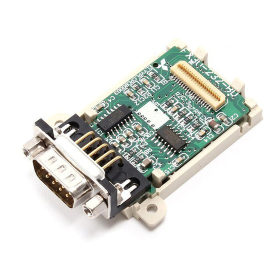
MODEL 100-240VAC 50/60Hz 40W OUT:30VDC/240VAC 2A(COSφ=1) SERIAL 570001 80M1 IND. CONT. EQ. MITSUBISHI ELECTRIC CORPORATION MADE IN JAPAN Control number Month (Example: 7=July) (1 to 9 = January to September, Apx. X = October, Y = November, Z = December) -
Page 110: Products Whose Production Was Stopped
FX Series PLC User's Manual - Data Communication Edition 1 Outline N:N Network 1.4 Programming Tool Applicability 1.3.2 Products whose production was stopped The table below shows FX series whose production (main unit, communication equipment, etc.) was stopped. Use the description on system configuration, etc. in this manual for maintenance. FX Series Date when production was stopped Remarks... - Page 111 FX Series PLC User's Manual - Data Communication Edition 1 Outline N:N Network 1.4 Programming Tool Applicability Model name Applicability Remarks (Software name) (applicable version) , FX and FX PLCs GX Developer (Ver. SW5 A or later) SW D5C(F)-GPPW-J FX-PCS/WIN (Ver.
-
Page 112: For Non-Applicable Versions (Setting An Alternative Model)
FX Series PLC User's Manual - Data Communication Edition 1 Outline N:N Network 1.4 Programming Tool Applicability Model name Applicability Remarks (Software name) (applicable version) GOT-F900 Series display units F940WGOT-TWD-E F940WGOT-TWD-E (Ver. 1.00 or later) F940GOT-*WD-E (Refer to right column.) F940GOT-LWD-E, F940GOT-SWD-E (Ver. -
Page 113: Specifications
FX Series PLC User's Manual - Data Communication Edition 2 Specifications N:N Network 2.1 Communication Specifications (Reference) Specifications This chapter explains the communication specifications and performance. Communication Specifications (Reference) Communication is executed according to the (fixed) specifications shown in the table below. Specification items such as baud rate cannot be changed. -
Page 114: Link Specifications
FX Series PLC User's Manual - Data Communication Edition 2 Specifications N:N Network 2.2 Link Specifications Link Specifications 2.2.1 Link patterns and number of link points in each FX Series The number of occupied link points varies depending on the number of slave stations used. For example, when three slave stations are connected in "Pattern 1", M1000 to M1223 and D0 to D33 are occupied, and unoccupied devices can be used as general devices for control. -
Page 115: Link Time
FX Series PLC User's Manual - Data Communication Edition 2 Specifications N:N Network 2.2 Link Specifications 2.2.2 Link time The link time indicates the cycle time in which link devices are updated. The link time varies depending on the number of linked units (master station and slave stations) and the number of linked devices as shown in the table below. -
Page 116: System Configuration And Equipment Selection
FX Series PLC User's Manual - Data Communication Edition 3 System Configuration and Equipment Selection N:N Network 3.1 System Configuration System Configuration and Equipment Selection This chapter explains the configuration of the communication equipment operating in accordance with RS- 485 and the system selection required by FX PLCs. System Configuration This section outlines the system configuration required to use the N:N Network. -
Page 117: Applicable Fx Plc And Communication Equipment
FX Series PLC User's Manual - Data Communication Edition 3 System Configuration and Equipment Selection N:N Network 3.2 Applicable FX PLC and Communication Equipment Applicable FX PLC and Communication Equipment Select a (optional) communication equipment combination, and put a check mark in the "Check" column. During selection, pay attention to the following: - In the table below, only the external dimensions are different between the units shown in "FX 485ADP/FX... - Page 118 FX Series PLC User's Manual - Data Communication Edition 3 System Configuration and Equipment Selection N:N Network 3.2 Applicable FX PLC and Communication Equipment Total extension FX Series Communication equipment (option) Check distance 50 m (164' 0") -485-BD (European terminal block) (14-point, 24-point 500 m type)
- Page 119 FX Series PLC User's Manual - Data Communication Edition 3 System Configuration and Equipment Selection N:N Network 3.2 Applicable FX PLC and Communication Equipment Total extension FX Series Communication equipment (option) Check distance When using channel 1 (ch 1) RD A 50 m RD B SD A...
- Page 120 FX Series PLC User's Manual - Data Communication Edition 3 System Configuration and Equipment Selection N:N Network 3.2 Applicable FX PLC and Communication Equipment Total extension FX Series Communication equipment (option) Check distance When using channel 1 (ch 1) 500 m (1640' 5") -485ADP(-MB) (European terminal block)
-
Page 121: Wiring
FX Series PLC User's Manual - Data Communication Edition 4 Wiring N:N Network 4.1 Wiring Procedure Wiring This chapter explains the wiring. WIRING PRECAUTIONS • Make sure to cut off all phases of the power supply externally before attempting installation or wiring work. Failure to do so may cause electric shock or damage to the product. -
Page 122: Selecting Cables And Terminal Resistors
Manufacturer Model name Remarks SPEV(SB)-0.2-2P Two-pair cable of 0.2 mm SPEV(SB)-MPC-0.2 × 3P Mitsubishi Cable Industries, Ltd. Three-pair cable of 0.2 mm SPEV(SB)-0.5-2P Two-pair cable of 0.5 mm KMPEV-SB CWS-178 0.2SQ × 2P Two-pair cable of 0.2 mm Showa Electric Wire & Cable Co., Ltd. -
Page 123: Connecting Cables
FX Series PLC User's Manual - Data Communication Edition 4 Wiring N:N Network 4.2 Selecting Cables and Terminal Resistors 4.2.2 Connecting cables 1. European type terminal block Use shielded twisted pair cables for connecting communication equipment operating in accordance with RS- 485. - Page 124 FX Series PLC User's Manual - Data Communication Edition 4 Wiring N:N Network 4.2 Selecting Cables and Terminal Resistors 2. Terminal block In the FX -485ADP and FX-485ADP, the terminal screw size is "M3". Make sure to use a crimp-style terminal with the following sizes. Make sure that the tightening torque is 0.5 to 0.8 N·m.
-
Page 125: Connecting Terminal Resistors
FX Series PLC User's Manual - Data Communication Edition 4 Wiring N:N Network 4.2 Selecting Cables and Terminal Resistors 4.2.3 Connecting terminal resistors Make sure to provide a terminal resistor at the end of each line. Brown Precision In the case of one-pair wiring, connect a terminal resistor to the RDA-RDB signal terminal of the communication equipment. -
Page 126: Connection Diagram
FX Series PLC User's Manual - Data Communication Edition 4 Wiring N:N Network 4.3 Connection Diagram Connection Diagram Use one-pair wiring for an N:N Network. -485-BD Communication -485-BD equipment in -485-BD accordance -485-BD RS-485 -485ADP -485ADP(-MB) -485ADP Terminal Terminal resistor: resistor: 110 Ω... -
Page 127: Communication Setting (Initialization) In Fx Programmable Controller
FX Series PLC User's Manual - Data Communication Edition 5 Communication Setting (Initialization) in FX Programmable Controller N:N Network 5.1 Check Procedure Communication Setting (Initialization) in FX Programmable Controller The communication setting is not required in FX PLCs for the N:N network. Using the following procedure, verify that the communication setting is not specified for another communication type and verify that the setting is correct. -
Page 128: Communication Setting Using Parameter Method (Gx Developer)
FX Series PLC User's Manual - Data Communication Edition 5 Communication Setting (Initialization) in FX Programmable Controller N:N Network 5.2 Communication Setting Using Parameter Method (GX Developer) Communication Setting Using Parameter Method (GX Developer) Communication setting may be changed using the parameter method with GX Developer and FXGP/WIN for Windows. -
Page 129: Communication Settings Using Parameter Method (Fxgp/Win)
FX Series PLC User's Manual - Data Communication Edition 5 Communication Setting (Initialization) in FX Programmable Controller N:N Network 5.3 Communication Settings Using Parameter Method (FXGP/WIN) Communication Settings Using Parameter Method (FXGP/WIN) Communication setting may be changed using the parameter method with GX Developer and FXGP/WIN for Windows. -
Page 130: Test Run (Communication Test)
FX Series PLC User's Manual - Data Communication Edition 6 Test Run (Communication Test) N:N Network 6.1 Test Procedure Test Run (Communication Test) This chapter explains the communication test procedures for the N:N Network. It is recommended to first wire the master station and slave stations, initialize communication settings in the FX PLCs, and then execute the communication test using the following procedure to confirm proper operation. - Page 131 FX Series PLC User's Manual - Data Communication Edition 6 Test Run (Communication Test) N:N Network 6.1 Test Procedure Confirming the link of slave stations Set the PLC inputs (X000 to X003) to ON or OFF in each slave station, and confirm that the outputs (Y004 to Y007, Y010 to Y013, Y014 to Y017...
-
Page 132: Creating Programs For The Communication Testing
FX Series PLC User's Manual - Data Communication Edition 6 Test Run (Communication Test) N:N Network 6.2 Creating Programs for the Communication Testing Creating Programs for the Communication Testing Create the programs shown below for the master station and each slave station. (In the communication test, set the refresh range to pattern 0.) 6.2.1 Creating a program for the master station... -
Page 133: Creating A Program For Each Slave Station
FX Series PLC User's Manual - Data Communication Edition 6 Test Run (Communication Test) N:N Network 6.2 Creating Programs for the Communication Testing 6.2.2 Creating a program for each slave station. Create the program shown below for the communication test. (This program is not required during actual operation.) Determine the station number of each slave station, and then transfer a program corresponding to the station number to each slave station. -
Page 134: Creating Programs
FX Series PLC User's Manual - Data Communication Edition 7 Creating Programs N:N Network 7.1 Checking Contents of Related Devices Creating Programs This chapter explains how to set the N:N Network and how to create programs. In N:N Network, pattern 0, 1 or 2 can be set according to the refresh range value. The number of used devices varies depending on the pattern. - Page 135 FX Series PLC User's Manual - Data Communication Edition 7 Creating Programs N:N Network 7.1 Checking Contents of Related Devices 2. Devices for determining errors in the N:N Network These devices are used for determining errors in the N:N Network. Use them to output link errors to the outside and interlock sequence programs.
-
Page 136: Creating Programs For Master Station (Station No. 0)
FX Series PLC User's Manual - Data Communication Edition 7 Creating Programs N:N Network 7.2 Creating Programs for Master Station (Station No. 0) Creating Programs for Master Station (Station No. 0) Create programs for the master station. Arbitrarily create programs for reading and writing link devices. Program for setting the N:N Network Make sure to start the program for setting the N:N Network Parameter setting... - Page 137 FX Series PLC User's Manual - Data Communication Edition 7 Creating Programs N:N Network 7.2 Creating Programs for Master Station (Station No. 0) Program for writing link devices (master station → slave station) This program is required to write information from the X000 master station to each slave station.
-
Page 138: Creating Programs For Slave Station (Station No. "N")
FX Series PLC User's Manual - Data Communication Edition 7 Creating Programs N:N Network 7.3 Creating Programs for Slave Station (Station No. "n") Creating Programs for Slave Station (Station No. "n") Create programs for the slave stations. Arbitrarily create programs for reading and writing link devices. Program for setting the N:N Network Make sure to start the program for setting the N:N Network Parameter setting... - Page 139 FX Series PLC User's Manual - Data Communication Edition 7 Creating Programs N:N Network 7.3 Creating Programs for Slave Station (Station No. "n") Program for reading link devices (slave station ← master or slave station) This program is required to read information from the master station or another slave station to a slave station.
-
Page 140: Cautions On Program Creation
FX Series PLC User's Manual - Data Communication Edition 7 Creating Programs N:N Network 7.4 Cautions on Program Creation Cautions on Program Creation 1. Effect on the operation cycle When the N:N Network is used, the operation cycle in each PLC becomes longer by about 10% regardless of the number of linked stations and adopted communication patterns. -
Page 141: Practical Program Examples
FX Series PLC User's Manual - Data Communication Edition 8 Practical Program Examples N:N Network 8.1 Practical Example 1 (Pattern 2) Practical Program Examples This chapter shows practical programs. Practical Example 1 (Pattern 2) This program example adopts pattern 2 which uses the maximum number of link devices. When an FX or FX PLC is included, however, only pattern 0 is applicable. -
Page 142: Setting Contents
FX Series PLC User's Manual - Data Communication Edition 8 Practical Program Examples N:N Network 8.1 Practical Example 1 (Pattern 2) 8.1.3 Setting contents The program examples shown later adopt the following communication parameters: System device Master station Station No. 1 Station No. - Page 143 FX Series PLC User's Manual - Data Communication Edition 8 Practical Program Examples N:N Network 8.1 Practical Example 1 (Pattern 2) 3. Operation program RUN monitor M8000 Operation [1] K1X000 K1M1000 Data transfer sequence error in slave station No. 1 M8184 Operation [2] K1M1064...
-
Page 144: Setting Program For Slave Station (No. 1)
FX Series PLC User's Manual - Data Communication Edition 8 Practical Program Examples N:N Network 8.1 Practical Example 1 (Pattern 2) 8.1.5 Setting program for slave station (No. 1) For the slave station setting program, refer to the program shown below. The program shown below consists of three blocks, "parameter setting program,"... - Page 145 FX Series PLC User's Manual - Data Communication Edition 8 Practical Program Examples N:N Network 8.1 Practical Example 1 (Pattern 2) 3. Operation program Counter reset X001 Master station Data transfer sequence error M8183 Operation [1] K1Y010 K1M1000 Operation [2] K1X000 K1M1064 Data transfer...
-
Page 146: Setting Program For Slave Station (No. 2)
FX Series PLC User's Manual - Data Communication Edition 8 Practical Program Examples N:N Network 8.1 Practical Example 1 (Pattern 2) 8.1.6 Setting program for slave station (No. 2) For the slave station setting program, refer to the program shown below. The program shown below consists of three blocks, "parameter setting program,"... - Page 147 FX Series PLC User's Manual - Data Communication Edition 8 Practical Program Examples N:N Network 8.1 Practical Example 1 (Pattern 2) 3. Operation program Counter reset X001 Master station Data transfer sequence error M8183 Operation [1] K1M1000 K1Y010 Data transfer sequence error in slave station No.
-
Page 148: Troubleshooting
FX Series PLC User's Manual - Data Communication Edition 9 Troubleshooting N:N Network 9.1 Checking FX PLC Version Applicability Troubleshooting This chapter explains troubleshooting. Checking FX PLC Version Applicability Verify that the FX Series PLC main unit is an applicable version. →... -
Page 149: Checking Setting Contents And Errors
FX Series PLC User's Manual - Data Communication Edition 9 Troubleshooting N:N Network 9.5 Checking Setting Contents and Errors 3. Presence of VRRD and VRSC instructions (except FX and FX PLCs) 1) Except FX and FX PLCs Verify that the VRRD and VRSC instructions are not used in the program. If these instructions are used, delete them, reboot the PLC’s power. -
Page 150: Checking Absence/Presence Of Data Transfer Errors
FX Series PLC User's Manual - Data Communication Edition 9 Troubleshooting N:N Network 9.6 Checking Absence/Presence of Data Transfer Errors 2. Checking setting errors 1) Error flags If the parameter setting includes an error, the serial communication error flag turns ON. Verify that the devices shown in the table below are ON. -
Page 151: Checking Error Codes
FX Series PLC User's Manual - Data Communication Edition 9 Troubleshooting N:N Network 9.6 Checking Absence/Presence of Data Transfer Errors 9.6.3 Checking error codes When a data transfer sequence error occurs, the corresponding data transfer sequence error flag turns ON, and the error code is stored in the corresponding data register. -
Page 152: Related Data
FX Series PLC User's Manual - Data Communication Edition 10 Related Data N:N Network 10.1 Related Device List 10. Related Data 10.1 Related Device List 10.1.1 For FX , FX , FX , FX , FX , FX , and FX PLCs 1. - Page 153 FX Series PLC User's Manual - Data Communication Edition 10 Related Data N:N Network 10.1 Related Device List Master Slave station Slave station Slave station Slave station Slave station Slave station Slave station station No. 1 No. 2 No. 3 No.
- Page 154 FX Series PLC User's Manual - Data Communication Edition 10 Related Data N:N Network 10.1 Related Device List 2. Word devices (data registers) Device Initial Detec- Name Description number value tion Devices for checking Corresponding station D8173 Provided to check the station number. —...
- Page 155 FX Series PLC User's Manual - Data Communication Edition 10 Related Data N:N Network 10.1 Related Device List Master Slave station Slave station Slave station Slave station Slave station Slave station Slave station station No. 1 No. 2 No. 3 No.
- Page 156 FX Series PLC User's Manual - Data Communication Edition 10 Related Data N:N Network 10.1 Related Device List 10.1.2 For FX and FX PLCs 1. Bit devices Device Initial Detec- Name Description number value tion Devices for communication setting M8038 Parameter setting Communication parameter setting flag —...
- Page 157 FX Series PLC User's Manual - Data Communication Edition 10 Related Data N:N Network 10.1 Related Device List Master Slave station Slave station Slave station Slave station Slave station Slave station Slave station station No. 1 No. 2 No. 3 No.
-
Page 158: Details Of Related Devices
FX Series PLC User's Manual - Data Communication Edition 10 Related Data N:N Network 10.2 Details of Related Devices 10.2 Details of Related Devices The devices described below are used in the N:N Network. 10.2.1 Parameter setting [M8038] This device works as the communication parameter setting flag. 1. -
Page 159: Data Transfer Sequence Error [M8138 To M8190] [M504 To M511]
FX Series PLC User's Manual - Data Communication Edition 10 Related Data N:N Network 10.2 Details of Related Devices 10.2.4 Data transfer sequence error [M8138 to M8190] [M504 to M511] These devices turn ON when a data transfer sequence error occurs in the master station or a slave station. 1. -
Page 160: Corresponding Station Number Settings Status [D8173]
FX Series PLC User's Manual - Data Communication Edition 10 Related Data N:N Network 10.2 Details of Related Devices 10.2.7 Corresponding station number settings status [D8173] This device is used to check the station’s own station number settings status. 1. Stations requiring program setting Setting is required for the master station and slave stations to check the setting status. -
Page 161: Slave Station Quantity Setting [D8177]
FX Series PLC User's Manual - Data Communication Edition 10 Related Data N:N Network 10.2 Details of Related Devices 10.2.11 Slave station quantity setting [D8177] Set a value ranging from 1 to 7 to the special data register D8177 (initial value: 7). 1. -
Page 162: Number Of Retries [D8179]
FX Series PLC User's Manual - Data Communication Edition 10 Related Data N:N Network 10.2 Details of Related Devices 4. Cautions on use 1) Cautions on using FX and FX PLCs When FX and/or FX PLCs are included in the system, make sure to set the refresh range to pattern If any other pattern is selected, data transfer error will occur in all FX and FX PLCs included in the... -
Page 163: Maximum Link Scan Time [D8202] [D202]
FX Series PLC User's Manual - Data Communication Edition 10 Related Data N:N Network 10.2 Details of Related Devices 10.2.16 Maximum link scan time [D8202] [D202] This device stores the maximum value of the network cycle in the N:N Network (unit: 10 ms). 1. -
Page 164: Data Transfer Error Code [D8211 To D8218] [D211 To D218]
FX Series PLC User's Manual - Data Communication Edition 10 Related Data N:N Network 10.2 Details of Related Devices 10.2.18 Data transfer error code [D8211 to D8218] [D211 to D218] These devices store the error code in the master station and slave stations. 1. - Page 165 This manual confers no industrial property rights or any rights of any other kind, nor does it confer any patent licenses. Mitsubishi Electric Corporation cannot be held responsible for any problems involving industrial property rights which may occur as a result of using the contents noted in this manual.
- Page 166 FX Series PLC User's Manual - Data Communication Edition Parallel Link...
-
Page 167: Outline
FX Series PLC User's Manual - Data Communication Edition 1 Outline Parallel Link 1.1 Outline of System Outline This chapter explains the parallel link. Outline of System The parallel link allows connection between two FX PLCs of the same series to mutually link devices. 1) According to the number of devices to be linked, either pattern can be selected between the regular mode and the high speed mode. -
Page 168: Procedures Before Operation
FX Series PLC User's Manual - Data Communication Edition 1 Outline Parallel Link 1.2 Procedures Before Operation Procedures Before Operation The flow chart below shows the Parallel Link setting procedures up until data link: Parallel link Refer to Chapter 1. Outline of system Outline •... -
Page 169: Communication Type Applicability In Plc
FX Series PLC User's Manual - Data Communication Edition 1 Outline Parallel Link 1.3 Communication Type Applicability in PLC Communication Type Applicability in PLC 1.3.1 Applicable versions The communication types are applicable in the following versions. : Applicable (If applicable versions of main units are limited, they are described inside ( ).) —: Not applicable Applicability (applicable version) Remarks... -
Page 170: Programming Tool Applicability
FX Series PLC User's Manual - Data Communication Edition 1 Outline Parallel Link 1.4 Programming Tool Applicability Programming Tool Applicability 1.4.1 For applicable versions The programming tool is applicable of main units for each FX Series from the following version: 1. - Page 171 FX Series PLC User's Manual - Data Communication Edition 1 Outline Parallel Link 1.4 Programming Tool Applicability 2. English versions : Applicable (If applicable versions of main units are limited, they are described inside ( ).) —: Not applicable Model name Applicability Remarks (Software name)
-
Page 172: For Non-Applicable Versions (Setting An Alternative Model)
FX Series PLC User's Manual - Data Communication Edition 1 Outline Parallel Link 1.4 Programming Tool Applicability 1.4.2 For non-applicable versions (setting an alternative model) Even software not applicable to a PLC can create programs when an alternative model is set. In this case, however, programming is enabled only in the function ranges provided for the alternative PLC model such as instructions and program size. -
Page 173: Specifications
FX Series PLC User's Manual - Data Communication Edition 2 Specifications Parallel Link 2.1 Communication Specifications (Reference) Specifications This chapter explains the communication specifications and performance of the parallel link. Communication Specifications (Reference) The parallel link is executed using the (fixed) communication specifications shown in the table below. Specification items such as baud rate cannot be changed. -
Page 174: Link Specifications
FX Series PLC User's Manual - Data Communication Edition 2 Specifications Parallel Link 2.2 Link Specifications Link Specifications 2.2.1 PLC communication type applicability status : Applicable (If applicable versions of main units are limited, they are described inside ( ).) —: Not applicable Regular parallel link mode applicability High speed parallel link mode applicability... -
Page 175: Link Device Numbers And Number Of Points
FX Series PLC User's Manual - Data Communication Edition 2 Specifications Parallel Link 2.3 Link Device Numbers and Number of Points Link Device Numbers and Number of Points 2.3.1 For FX and FX Series Regular parallel link mode High speed parallel link mode Mode Bit device (M) Word device (D) - Page 176 FX Series PLC User's Manual - Data Communication Edition 2 Specifications Parallel Link 2.3 Link Device Numbers and Number of Points 2.3.2 For FX (FX), FX , FX , FX , FX , FX , FX , FX and FX Series Regular parallel link mode High speed parallel link mode...
-
Page 177: System Configuration And Selection
FX Series PLC User's Manual - Data Communication Edition 3 System Configuration and Selection Parallel Link 3.1 System Configuration System Configuration and Selection This chapter explains the configuration of communication equipment operating in accordance with RS-485 and the system selection required by FX PLCs. System Configuration This section outlines the system configuration required to use the parallel link. -
Page 178: Configuration Of Each Group
FX Series PLC User's Manual - Data Communication Edition 3 System Configuration and Selection Parallel Link 3.2 Configuration of Each Group Configuration of Each Group indicate the communication equipment combination patterns. 1. Group 1 (FX and FX Series) Total extension Communication equipment operating FX PLC Important point in selection... - Page 179 FX Series PLC User's Manual - Data Communication Edition 3 System Configuration and Selection Parallel Link 3.2 Configuration of Each Group 2. Group 2 (FX Series) Communication equipment operating Total extension FX PLC Important point in selection in accordance with RS-485 distance This is the communication board 50 m...
- Page 180 FX Series PLC User's Manual - Data Communication Edition 3 System Configuration and Selection Parallel Link 3.2 Configuration of Each Group 4. Group 4 (FX and FX Series) Total extension Communication equipment operating FX PLC Important point in selection in accordance with RS-485 distance This is the communication board 50 m...
- Page 181 FX Series PLC User's Manual - Data Communication Edition 3 System Configuration and Selection Parallel Link 3.2 Configuration of Each Group 7. Group 7 (FX (FX) and FX Series) Communication equipment using Total extension FX PLC Important point in selection optical fiber or in accordance distance with RS-485...
-
Page 182: Applicable Fx Plc And Communication Equipment
FX Series PLC User's Manual - Data Communication Edition 3 System Configuration and Selection Parallel Link 3.3 Applicable FX PLC and Communication Equipment Applicable FX PLC and Communication Equipment Select a (optional) communication equipment combination, and put a check mark in the "Check" column. During selection, pay attention to the following: - In the table below, only the external dimensions are different between the units shown in "FX 485ADP/FX... - Page 183 FX Series PLC User's Manual - Data Communication Edition 3 System Configuration and Selection Parallel Link 3.3 Applicable FX PLC and Communication Equipment Total extension FX Series Communication equipment (option) Check distance 50 m (164' 0") -485-BD (European terminal block) (14-point, 24-point 500 m type)
- Page 184 FX Series PLC User's Manual - Data Communication Edition 3 System Configuration and Selection Parallel Link 3.3 Applicable FX PLC and Communication Equipment Total extension FX Series Communication equipment (option) Check distance When using channel 1 (ch 1) RD A 50 m RD B SD A...
- Page 185 FX Series PLC User's Manual - Data Communication Edition 3 System Configuration and Selection Parallel Link 3.3 Applicable FX PLC and Communication Equipment Total extension FX Series Communication equipment (option) Check distance When using channel 1 (ch 1) 500 m (1640' 5") -485ADP(-MB) (European terminal block)
- Page 186 FX Series PLC User's Manual - Data Communication Edition 3 System Configuration and Selection Parallel Link 3.3 Applicable FX PLC and Communication Equipment Total extension FX Series Communication equipment (option) Check distance 50 m (164' 0") -40AP (for optical fiber) (FX) 10 m (32' 9")
-
Page 187: Wiring
FX Series PLC User's Manual - Data Communication Edition 4 Wiring Parallel Link 4.1 Wiring Procedure Wiring This chapter explains the wiring. WIRING PRECAUTIONS • Make sure to cut off all phases of the power supply externally before attempting installation or wiring work. Failure to do so may cause electric shock or damage to the product. -
Page 188: Selecting Cables And Terminal Resistors
Manufacturer Model name Remarks SPEV(SB)-0.2-2P Two-pair cable of 0.2 mm SPEV(SB)-MPC-0.2 × 3P Mitsubishi Cable Industries, Ltd. Three-pair cable of 0.2 mm SPEV(SB)-0.5-2P Two-pair cable of 0.5 mm KMPEV-SB CWS-178 0.2SQ × 2P Two-pair cable of 0.2 mm Showa Electric Wire & Cable Co., Ltd. -
Page 189: Connecting Cables
FX Series PLC User's Manual - Data Communication Edition 4 Wiring Parallel Link 4.2 Selecting Cables and Terminal Resistors 4.2.2 Connecting cables 1. European type terminal block Use shielded twisted pair cables for connecting communication equipment operating in accordance with RS- 485. -
Page 190: Optical Fiber Cable
FX Series PLC User's Manual - Data Communication Edition 4 Wiring Parallel Link 4.2 Selecting Cables and Terminal Resistors 2. Terminal block In the FX -485ADP and FX-485ADP, the terminal screw size is "M3". Make sure to use a crimp-style terminal with the following sizes. Make sure that the tightening torque is 0.5 to 0.8 N·m. -
Page 191: Connecting Terminal Resistors
FX Series PLC User's Manual - Data Communication Edition 4 Wiring Parallel Link 4.2 Selecting Cables and Terminal Resistors 4.2.4 Connecting terminal resistors In the case of one-pair wiring, connect a terminal resistor to the RDA-RDB signal Brown Precision terminal of the communication equipment. In the case of two-pair wiring, connect a terminal resistor to the RDA-RDB signal terminal and SDA-SDB terminal of the communication equipment. -
Page 192: Connection Diagram
FX Series PLC User's Manual - Data Communication Edition 4 Wiring Parallel Link 4.3 Connection Diagram Connection Diagram 4.3.1 For FX , FX and FX PLCs 1. In the case of one-pair wiring -485-BD -485-BD -485-BD -485-BD -485ADP(-MB) -485ADP(-MB) Terminal Termina resistor l resistor... - Page 193 FX Series PLC User's Manual - Data Communication Edition 4 Wiring Parallel Link 4.3 Connection Diagram 4.3.2 For FX , FX , FX , FX and FX PLCs 1. In the case of one-pair wiring -485-BD -485-BD -485ADP -485-BD -485ADP -485ADP -485-BD -485ADP...
-
Page 194: Grounding
FX Series PLC User's Manual - Data Communication Edition 4 Wiring Parallel Link 4.4 Grounding 4.3.3 For FX (FX) and FX PLCs -40AW -40AW -40AP -40AP *1 Connect the terminal to the terminal in each PLC (main unit). Grounding Grounding should be performed as stated below. •... -
Page 195: Communication Setting (Initialization) In Fx Programmable Controller
FX Series PLC User's Manual - Data Communication Edition 5 Communication Setting (Initialization) in FX Programmable Controller Parallel Link 5.1 Check Procedure Communication Setting (Initialization) in FX Programmable Controller The communication setting is not required in FX PLCs for parallel link. If the communication setting is already provided for another communication type or for checking the existing communication setting, perform the following procedure. -
Page 196: Communication Setting Using Parameter Method (Gx Developer)
FX Series PLC User's Manual - Data Communication Edition 5 Communication Setting (Initialization) in FX Programmable Controller Parallel Link 5.2 Communication Setting Using Parameter Method (GX Developer) Communication Setting Using Parameter Method (GX Developer) Communication settings may be changed using the parameter method with GX Developer and FXGP/WIN for Windows. -
Page 197: Communication Setting Using Parameter Method (Fxgp/Win)
FX Series PLC User's Manual - Data Communication Edition 5 Communication Setting (Initialization) in FX Programmable Controller Parallel Link 5.3 Communication Setting Using Parameter Method (FXGP/WIN) Communication Setting Using Parameter Method (FXGP/WIN) Communication settings may be changed using the parameter method with GX Developer and FXGP/WIN for Windows. -
Page 198: Test Run (Communication Test)
FX Series PLC User's Manual - Data Communication Edition 6 Test Run (Communication Test) Parallel Link 6.1 Test Procedure Test Run (Communication Test) This chapter explains the communication test procedures for the parallel link. It is recommended to wire the master station and slave station, initialize communication settings in the FX PLCs, and then execute the communication test using the following procedure to confirm the proper operation. -
Page 199: Creating Programs For The Communication Test
FX Series PLC User's Manual - Data Communication Edition 6 Test Run (Communication Test) Parallel Link 6.2 Creating Programs for the Communication Test Confirming the link of the slave station Set the PLC inputs (X000 to X003) to ON or OFF in the slave station, and confirm that the outputs (Y000 to Y003) turn ON or OFF in the master station. - Page 200 FX Series PLC User's Manual - Data Communication Edition 6 Test Run (Communication Test) Parallel Link 6.2 Creating Programs for the Communication Test 2. Program for communication test (for the slave station) Create the program shown below for the communication test. (This program is not required during actual operation.) M8000 M8071...
-
Page 201: Creating Programs
FX Series PLC User's Manual - Data Communication Edition 7 Creating Programs Parallel Link 7.1 Regular Parallel Link Mode Creating Programs The parallel link has two modes, regular parallel link mode and high speed parallel link mode. Program settings and the number of device to be used are different in each mode. When connecting FX PLCs in the parallel link, use the same mode in both PLCs. - Page 202 FX Series PLC User's Manual - Data Communication Edition 7 Creating Programs Parallel Link 7.1 Regular Parallel Link Mode 3. Link devices 1) Sending devices for the master station These devices are used for sending the information from the master station to the slave station. To prevent malfunctions, do not change the setting of these devices in the slave station.
-
Page 203: Creating Programs For Master Station
FX Series PLC User's Manual - Data Communication Edition 7 Creating Programs Parallel Link 7.1 Regular Parallel Link Mode 7.1.2 Creating programs for master station Create programs for the master station. RUN monitor Master station setting Program for setting the master station M8000 M8070 M8070 is set to ON to set a PLC as the master station. -
Page 204: Creating Programs For Slave Station
FX Series PLC User's Manual - Data Communication Edition 7 Creating Programs Parallel Link 7.1 Regular Parallel Link Mode 7.1.3 Creating programs for slave station Create programs for the slave station. RUN monitor Slave station setting Program for setting the slave station M8000 M8071 M8071 is set to ON to set a PLC as the slave station. -
Page 205: High Speed Parallel Link Mode
FX Series PLC User's Manual - Data Communication Edition 7 Creating Programs Parallel Link 7.2 High Speed Parallel Link Mode High Speed Parallel Link Mode This section explains the program setting method in the high speed parallel link mode. 7.2.1 Checking contents of related devices The tables below show devices used in the parallel link. - Page 206 FX Series PLC User's Manual - Data Communication Edition 7 Creating Programs Parallel Link 7.2 High Speed Parallel Link Mode 2) Sending devices for the slave station These devices are used for sending the information from the slave station to the master station. To prevent malfunctions, do not change the setting of these devices in the master station.
-
Page 207: Creating Programs For Master Station
FX Series PLC User's Manual - Data Communication Edition 7 Creating Programs Parallel Link 7.2 High Speed Parallel Link Mode 7.2.2 Creating programs for master station Create programs for the master station. RUN monitor Master station setting Program for setting the master station M8000 M8070 M8070 is set to ON to set a PLC as the master station. -
Page 208: Creating Programs For Slave Station
FX Series PLC User's Manual - Data Communication Edition 7 Creating Programs Parallel Link 7.2 High Speed Parallel Link Mode 7.2.3 Creating programs for slave station Create programs for the slave station. RUN monitor Slave station setting Program for setting the slave station M8000 M8071 M8071 is set to ON to set a PLC as the slave station. -
Page 209: Cautions On Program Creation
FX Series PLC User's Manual - Data Communication Edition 7 Creating Programs Parallel Link 7.3 Cautions on Program Creation Cautions on Program Creation 1. Program for reading link devices 1) Do not change the contents of link devices for the other station. 2) When a link error occurs, the link device information remains the same as the status just before the error. -
Page 210: Practical Program Examples
FX Series PLC User's Manual - Data Communication Edition 8 Practical Program Examples Parallel Link 8.1 Practical Example 1 (Regular Parallel Link Mode) Practical Program Examples This chapter shows practical programs examples. Practical Example 1 (Regular Parallel Link Mode) When many link devices are required, use the regular parallel link mode. 8.1.1 System configuration example The example below shows a system configuration in which two FX... -
Page 211: Program For Master Station
FX Series PLC User's Manual - Data Communication Edition 8 Practical Program Examples Parallel Link 8.1 Practical Example 1 (Regular Parallel Link Mode) 8.1.3 Program for master station For the master station, refer to the program shown below. RUN monitor M8000 M8070 RUN monitor... -
Page 212: Troubleshooting
FX Series PLC User's Manual - Data Communication Edition 9 Troubleshooting Parallel Link 9.1 Checking FX PLC Version Applicability Troubleshooting This chapter explains troubleshooting. Checking FX PLC Version Applicability Verify that the FX PLC main unit is an applicable version. →... -
Page 213: Checking Sequence Program
FX Series PLC User's Manual - Data Communication Edition 9 Troubleshooting Parallel Link 9.4 Checking Sequence Program Checking Sequence Program 1. Communication setting in the sequence program Verify that N:N Network (D8173 to D8180) is not set. Using both the parallel link and N:N Network at the same time is not allowed. -
Page 214: Checking Absence/Presence Of Errors
FX Series PLC User's Manual - Data Communication Edition 9 Troubleshooting Parallel Link 9.5 Checking Absence/Presence of Errors Checking Absence/Presence of Errors Verify that errors have not occurred in the master station and slave station. Errors can be checked using the flags shown below. -
Page 215: Related Data
FX Series PLC User's Manual - Data Communication Edition 10 Related Data Parallel Link 10.1 Related Device List 10. Related Data 10.1 Related Device List 1. Bit devices Device Initial Detec- Name Description number value tion Devices for communication setting Parallel link master −... -
Page 216: Details Of Related Devices
FX Series PLC User's Manual - Data Communication Edition 10 Related Data Parallel Link 10.2 Details of Related Devices 10.2 Details of Related Devices The devices described below are used in parallel link. 10.2.1 Parallel link master station declare [M8070] When this device is set to ON, the PLC is handled as the master station in the parallel link. -
Page 217: Parallel Link On [M8072]
FX Series PLC User's Manual - Data Communication Edition 10 Related Data Parallel Link 10.2 Details of Related Devices 3. Cautions on use Set this device to ON using a sequence program. 10.2.5 Parallel link ON [M8072] This device is provided to verify that the parallel link is being executed. 1. -
Page 218: Serial Communication Error Code [D8063 And D8438]
FX Series PLC User's Manual - Data Communication Edition 10 Related Data Parallel Link 10.2 Details of Related Devices 10.2.9 Serial communication error code [D8063 and D8438] These devices store the serial communication error code. (D8438 is available only in the FX , FX 1. - Page 219 This manual confers no industrial property rights or any rights of any other kind, nor does it confer any patent licenses. Mitsubishi Electric Corporation cannot be held responsible for any problems involving industrial property rights which may occur as a result of using the contents noted in this manual.
- Page 220 FX Series PLC User's Manual - Data Communication Edition Computer Link...
-
Page 221: Outline
FX Series PLC User's Manual - Data Communication Edition 1 Outline Computer Link 1.1 Outline of System Outline This chapter explains computer link. Outline of System Computer link allows connection of up to sixteen FX PLCs and A PLCs to a personal computer working as the master station to link data. -
Page 222: Procedures Before Operation
FX Series PLC User's Manual - Data Communication Edition 1 Outline Computer Link 1.2 Procedures Before Operation Procedures Before Operation The flow chart below shows the Computer Link setting procedures up until data link. Computer link Refer to Chapter 1. Outline of system Outline •... -
Page 223: Communication Type Applicability In Plc
MODEL 100-240VAC 50/60Hz 40W OUT:30VDC/240VAC 2A(COSφ=1) SERIAL 570001 80M1 IND. CONT. EQ. MITSUBISHI ELECTRIC CORPORATION MADE IN JAPAN Control number Month (Example: 7=July) (1 to 9 = January to September, Apx. X = October, Y = November, Z = December) -
Page 224: Products Whose Production Was Stopped
FX Series PLC User's Manual - Data Communication Edition 1 Outline Computer Link 1.4 Programming Tool Applicability 1.3.2 Products whose production was stopped The table below shows FX series whose production (main unit, communication equipment, etc.) was stopped. Use the description on system configuration, etc. in this manual for maintenance. Date when production was stopped Remarks Series... - Page 225 FX Series PLC User's Manual - Data Communication Edition 1 Outline Computer Link 1.4 Programming Tool Applicability Model name Applicability Remarks (Software name) (applicable version) , FX and FX PLCs GX Developer (Ver. SW5 A or later) SW D5C(F)-GPPW-J FX-PCS/WIN (Ver.
- Page 226 FX Series PLC User's Manual - Data Communication Edition 1 Outline Computer Link 1.4 Programming Tool Applicability Model name Applicability Remarks (Software name) (applicable version) GOT-F900 Series display units F940WGOT-TWD-E F940WGOT-TWD-E (Ver. 1.00 or later) F940GOT-*WD-E (Refer to right column.) F940GOT-LWD-E, F940GOT-SWD-E (Ver.
-
Page 227: For Non-Applicable Versions (Setting An Alternative Model)
FX Series PLC User's Manual - Data Communication Edition 1 Outline Computer Link 1.4 Programming Tool Applicability 1.4.2 For non-applicable versions (setting an alternative model) Even software not applicable to a PLC can create programs when an alternative model is set. In this case, however, programming is enabled only in the function ranges provided for the alternative PLC model such as instructions and program size. -
Page 228: Specifications
FX Series PLC User's Manual - Data Communication Edition 2 Specifications Computer Link 2.1 Communication Specifications (Reference) Specifications This chapter explains the communication specifications and performance. Communication Specifications (Reference) Communication is executed within the specifications shown in the table below. The baud rate, etc. can be changed in the parameter settings of a programming tool or in a sequence program. -
Page 229: Link Specifications
FX Series PLC User's Manual - Data Communication Edition 2 Specifications Computer Link 2.2 Link Specifications Link Specifications 2.2.1 Applicable commands and number of device points Number of points processed in Command one-time update (FX), Name Contents of processing Sym- ASCII , FX , FX... -
Page 230: Applicable Device Ranges
FX Series PLC User's Manual - Data Communication Edition 2 Specifications Computer Link 2.2 Link Specifications 2.2.2 Applicable device ranges The tables below show devices and device number ranges applicable for the device memory access. • Construct each of the BR, BW, BT, WR, WW, and WT commands in five characters. Device Device number = 5 characters... - Page 231 FX Series PLC User's Manual - Data Communication Edition 2 Specifications Computer Link 2.2 Link Specifications 2. Word devices Available Device Device number range (character) commands number Device expression (FX), Decimal/ Octal , WT TN000 to TN000 to TN000 to TN063 TN000 to TN255 —...
-
Page 232: Link Time
FX Series PLC User's Manual - Data Communication Edition 2 Specifications Computer Link 2.2 Link Specifications 2.2.3 Link time 1. Data transfer Data transfer Data transfer Interval time 2. Data transfer time + 4 × Number Time to read continuous word devices (timers, counters or data registers) in one station = (21 ) ×... - Page 233 FX Series PLC User's Manual - Data Communication Edition 2 Specifications Computer Link 2.2 Link Specifications The maximum number of points is 64 for the FX (FX), FX , FX , FX , FX , FX , FX , FX and FX Series.
-
Page 234: System Configuration And Equipment Selection
FX Series PLC User's Manual - Data Communication Edition 3 System Configuration and Equipment Selection Computer Link 3.1 System Configuration System Configuration and Equipment Selection This chapter explains the system configuration and communication equipment selection operating in accordance with RS-485 or RS-232C required by FX PLCs. System Configuration This section outlines the system configuration required to use computer link. -
Page 235: Applicable Fx Plc And Communication Equipment
FX Series PLC User's Manual - Data Communication Edition 3 System Configuration and Equipment Selection Computer Link 3.2 Applicable FX PLC and Communication Equipment Applicable FX PLC and Communication Equipment Select a (optional) communication equipment combination, and put a check mark in the "Check" column. During selection, pay attention to the following: - Computer link is not provided for the FX , FX... - Page 236 FX Series PLC User's Manual - Data Communication Edition 3 System Configuration and Equipment Selection Computer Link 3.2 Applicable FX PLC and Communication Equipment Total extension FX Series Communication equipment (option) Check distance 15 m (49' 2") -232-BD (9-pin D-Sub, male) (14-point, 24-point 15 m type)
- Page 237 FX Series PLC User's Manual - Data Communication Edition 3 System Configuration and Equipment Selection Computer Link 3.2 Applicable FX PLC and Communication Equipment Total extension FX Series Communication equipment (option) Check distance When using channel 1 (ch 1) 15 m (49' 2") -232-BD (9-pin D-Sub, male)
- Page 238 FX Series PLC User's Manual - Data Communication Edition 3 System Configuration and Equipment Selection Computer Link 3.2 Applicable FX PLC and Communication Equipment Total extension FX Series Communication equipment (option) Check distance When using channel 1 (ch 1) 15 m (49' 2") -232ADP(-MB) (9-pin D-Sub, male)
- Page 239 FX Series PLC User's Manual - Data Communication Edition 3 System Configuration and Equipment Selection Computer Link 3.2 Applicable FX PLC and Communication Equipment Total extension FX Series Communication equipment (option) Check distance 15 m (49' 2") FX-232ADP (FX) (25-pin D-Sub, female) 15 m (49' 2") FX-232ADP...
-
Page 240: For Communication In Accordance With Rs-485
FX Series PLC User's Manual - Data Communication Edition 3 System Configuration and Equipment Selection Computer Link 3.2 Applicable FX PLC and Communication Equipment 3.2.2 For communication in accordance with RS-485. Total extension FX Series Communication equipment (option) Check distance 500 m (1640' 5") -485ADP... - Page 241 FX Series PLC User's Manual - Data Communication Edition 3 System Configuration and Equipment Selection Computer Link 3.2 Applicable FX PLC and Communication Equipment Total extension FX Series Communication equipment (option) Check distance 50 m (164' 0") -485-BD (European terminal block) (14-point, 24-point 500 m type)
- Page 242 FX Series PLC User's Manual - Data Communication Edition 3 System Configuration and Equipment Selection Computer Link 3.2 Applicable FX PLC and Communication Equipment Total extension FX Series Communication equipment (option) Check distance When using channel 1 (ch 1) RD A 50 m RD B SD A...
- Page 243 FX Series PLC User's Manual - Data Communication Edition 3 System Configuration and Equipment Selection Computer Link 3.2 Applicable FX PLC and Communication Equipment Total extension FX Series Communication equipment (option) Check distance When using channel 1 (ch 1) 500 m (1640' 5") -485ADP(-MB) (European terminal block)
- Page 244 FX Series PLC User's Manual - Data Communication Edition 3 System Configuration and Equipment Selection Computer Link 3.2 Applicable FX PLC and Communication Equipment Total extension FX Series Communication equipment (option) Check distance 500 m (1640' 5") FX-485ADP (Terminal block) 500 m (1640' 5") FX-485ADP...
-
Page 245: Wiring
FX Series PLC User's Manual - Data Communication Edition 4 Wiring Computer Link 3.2 Applicable FX PLC and Communication Equipment Wiring This chapter explains the wiring. WIRING PRECAUTIONS • Make sure to cut off all phases of the power supply externally before attempting installation or wiring work. Failure to do so may cause electric shock or damage to the product. -
Page 246: Wiring Procedure
FX Series PLC User's Manual - Data Communication Edition 4 Wiring Computer Link 4.1 Wiring Procedure Wiring Procedure Selecting the connection method Select the wiring method suitable to the application. → For details, refer to Section 4.2. Preparing for wiring Prepare cables and terminal resistors required for wiring. -
Page 247: Selecting Connection Method
FX Series PLC User's Manual - Data Communication Edition 4 Wiring Computer Link 4.2 Selecting Connection Method Selecting Connection Method When using computer link, communication can be achieved in accordance with RS-232C or RS-485 (422). In FX and FX PLCs, computer link is applicable in up to two channels at the same time. In such a case, communication can be achieved in accordance with RS-232C on both channels, in accordance with RS-485 on both channels, or in accordance with RS-232C on one channel and RS-485 on the other channel. -
Page 248: Selecting Cables And Terminal Resistors (Rs-485)
Manufacturer Model name Remarks SPEV(SB)-0.2-2P Two-pair cable of 0.2 mm SPEV(SB)-MPC-0.2 × 3P Mitsubishi Cable Industries, Ltd. Three-pair cable of 0.2 mm SPEV(SB)-0.5-2P Two-pair cable of 0.5 mm KMPEV-SB CWS-178 0.2SQ × 2P Two-pair cable of 0.2 mm Showa Electric Wire & Cable Co., Ltd. -
Page 249: Connecting Cables
FX Series PLC User's Manual - Data Communication Edition 4 Wiring Computer Link 4.3 Selecting Cables and Terminal Resistors (RS-485) 4.3.2 Connecting cables 1. European type terminal block Use shielded twisted pair cables for connecting communication equipment operating in accordance with RS- 485. - Page 250 FX Series PLC User's Manual - Data Communication Edition 4 Wiring Computer Link 4.3 Selecting Cables and Terminal Resistors (RS-485) 2. Terminal block In the FX -485ADP and FX-485ADP, the terminal screw size is "M3". Make sure to use a crimp-style terminal with the following sizes. Make sure that the tightening torque is 0.5 to 0.8 N·m.
-
Page 251: Connecting Terminal Resistors
FX Series PLC User's Manual - Data Communication Edition 4 Wiring Computer Link 4.3 Selecting Cables and Terminal Resistors (RS-485) 4.3.3 Connecting terminal resistors Make sure to provide a terminal resistor at the end of each line. In the case of one-pair wiring, connect a terminal resistor to the RDA-RDB signal Brown Precision terminal of the communication equipment. -
Page 252: Connection Diagram For Rs-232C
FX Series PLC User's Manual - Data Communication Edition 4 Wiring Computer Link 4.4 Connection Diagram for RS-232C Connection Diagram for RS-232C Representative wiring examples are shown in this section. When pin numbers in the external equipment are different, wire the pins as shown below. 4.4.1 Connection diagram between FX PLC and personal computer External equipment operating in accordance... -
Page 253: Connection Diagram For Rs-485 And Rs-422
FX Series PLC User's Manual - Data Communication Edition 4 Wiring Computer Link 4.5 Connection Diagram for RS-485 and RS-422 Connection Diagram for RS-485 and RS-422 4.5.1 One-pair wiring -485-BD Communication -485-BD equipment operating -485-BD in accordance with -485-BD RS-485 -485ADP -485ADP(-MB) -485ADP... -
Page 254: Grounding
FX Series PLC User's Manual - Data Communication Edition 4 Wiring Computer Link 4.6 Grounding Grounding Grounding should be performed as stated below. • The grounding resistance should be 100Ω or less. • Independent grounding should be performed for best results. When independent grounding can not be performed, perform "shared grounding"... -
Page 255: Communication Setting In Fx Programmable Controller
FX Series PLC User's Manual - Data Communication Edition 5 Communication Setting in FX Programmable Controller Computer Link 5.1 Communication Setting Methods Communication Setting in FX Programmable Controller This chapter explains the communication setting method types and setting methods for computer link. Communication Setting Methods This section explains the communication setting methods and setting procedures in FX PLCs. -
Page 256: Communication Setting Using Parameter Method (Gx Developer)
FX Series PLC User's Manual - Data Communication Edition 5 Communication Setting in FX Programmable Controller Computer Link 5.2 Communication Setting Using Parameter Method (GX Developer) 4. Time at which the settings become valid 1) When specifying the setting using parameters: When the PLC power is turned ON, the parameters set using the parameter setting window in the sequence programming software are automatically transferred to the PLC. - Page 257 FX Series PLC User's Manual - Data Communication Edition 5 Communication Setting in FX Programmable Controller Computer Link 5.2 Communication Setting Using Parameter Method (GX Developer) Setting the serial communication (parameters) Select a channel and check the box labeled "Operate communication setting" box, then adjust the parameters for that channel.
-
Page 258: Communication Settings Using Parameter Method (Fxgp/Win)
FX Series PLC User's Manual - Data Communication Edition 5 Communication Setting in FX Programmable Controller Computer Link 5.3 Communication Settings Using Parameter Method (FXGP/WIN) Communication Settings Using Parameter Method (FXGP/WIN) Communication settings may be changed by the parameter method with GX Developer and FXGP/WIN for Windows. - Page 259 FX Series PLC User's Manual - Data Communication Edition 5 Communication Setting in FX Programmable Controller Computer Link 5.3 Communication Settings Using Parameter Method (FXGP/WIN) 2. When there are already parameter settings The existing communication setting contents are displayed. Adjusting serial setting (parameter) Execute the communication setting as shown below.
-
Page 260: Control Procedures And Setting Methods
FX Series PLC User's Manual - Data Communication Edition 6 Control Procedures and Setting Methods Computer Link 6.1 Data Flow by Link Control Procedures and Setting Methods Data Flow by Link The figures below show images of data flow achieved when data is read from or written to a PLC CPU and the status is controlled. -
Page 261: Important Points In Computer Link
FX Series PLC User's Manual - Data Communication Edition 6 Control Procedures and Setting Methods Computer Link 6.2 Important Points in Computer Link Important Points in Computer Link This section explains important points to be understood before creating programs for computer link. 6.2.1 Operations of PLC caused by data transfer The PLC operations and scan time using computer link are as described below. -
Page 262: Sum Check Code
FX Series PLC User's Manual - Data Communication Edition 6 Control Procedures and Setting Methods Computer Link 6.3 How to Understand Control Procedure How to Understand Control Procedure This section explains how to understand the transfer data shown in the later description of each function. 1. -
Page 263: Control Procedure Format 1
FX Series PLC User's Manual - Data Communication Edition 6 Control Procedures and Setting Methods Computer Link 6.4 Basic Formats of Dedicated Protocol 6.4.1 Control procedure format 1 The table below shows the control procedure for format 1. Description Control procedure (protocol) Transfer order Character When... -
Page 264: Control Procedure Format 4
FX Series PLC User's Manual - Data Communication Edition 6 Control Procedures and Setting Methods Computer Link 6.4 Basic Formats of Dedicated Protocol 6.4.2 Control procedure format 4 The table below shows the control procedure for format 4. Description Control procedure (protocol) Transfer order Character When... -
Page 265: Contents Of Set Items In Each Control Procedure (Protocol)
FX Series PLC User's Manual - Data Communication Edition 6 Control Procedures and Setting Methods Computer Link 6.4 Basic Formats of Dedicated Protocol 6.4.3 Contents of set items in each control procedure (protocol) This subsection explains the contents of the data used in each control procedure. 1. - Page 266 FX Series PLC User's Manual - Data Communication Edition 6 Control Procedures and Setting Methods Computer Link 6.4 Basic Formats of Dedicated Protocol 3. PLC number The PLC number is used to identify a PLC to be accessed when computer link is combined with the MELSECNET (II) or MELSECNET/B in A Series PLCs.
-
Page 267: Time-Out Time Setting
FX Series PLC User's Manual - Data Communication Edition 6 Control Procedures and Setting Methods Computer Link 6.4 Basic Formats of Dedicated Protocol 6.4.4 Time-out time setting When the receiving of data from the computer is interrupted and is not restarted within the preset time (time- out time setting), the PLC regards the situation as a timeout error and initializes the transfer sequence. -
Page 268: Transfer Sequence Time Chart And Communication Time
FX Series PLC User's Manual - Data Communication Edition 6 Control Procedures and Setting Methods Computer Link 6.5 Transfer Sequence Time Chart and Communication Time Transfer Sequence Time Chart and Communication Time This section explains the communication time chart between the computer and the PLC. As shown in the figures below, communication between the computer and the PLC is always executed after "END". -
Page 269: Transfer Time In Transfer Sequence
FX Series PLC User's Manual - Data Communication Edition 6 Control Procedures and Setting Methods Computer Link 6.5 Transfer Sequence Time Chart and Communication Time 6.5.3 Transfer time in transfer sequence This subsection explains how to calculate the approximate time after the computer starts data transfer and the PLC gives a response until all communication is completed. -
Page 270: Transfer Data In Character Area
FX Series PLC User's Manual - Data Communication Edition 6 Control Procedures and Setting Methods Computer Link 6.6 Transfer Data in Character Area Transfer Data in Character Area This section explains the transfer data in the character area sent and received between the computer and a PLC using each command. -
Page 271: When Word Device Memory Is Read Or Written
FX Series PLC User's Manual - Data Communication Edition 6 Control Procedures and Setting Methods Computer Link 6.6 Transfer Data in Character Area 6.6.2 When word device memory is read or written In the case of word device memory, one word is expressed in 4-bit units in turn from the most significant bit in hexadecimal. -
Page 272: Commands
FX Series PLC User's Manual - Data Communication Edition 7 Commands Computer Link 6.6 Transfer Data in Character Area Commands This chapter explains specification methods and specification examples of commands in dedicated protocols used in computer link communication type. For control procedures in dedicated protocols, refer to "6. Control Procedures and Setting Methods". The table below shows a reference section for each command. -
Page 273: Br Command [Reads Device Memory In 1-Bit Units]
FX Series PLC User's Manual - Data Communication Edition 7 Commands Computer Link 7.1 BR Command [Reads Device Memory in 1-Bit Units] BR Command [Reads Device Memory in 1-Bit Units] This section explains the control procedure specification method and specification example when the bit device memory is read all at once. -
Page 274: Wr Command [Reads Device Memory In 1-Word Units]
FX Series PLC User's Manual - Data Communication Edition 7 Commands Computer Link 7.2 WR Command [Reads Device Memory in 1-Word Units] WR Command [Reads Device Memory in 1-Word Units] This section explains the control procedure specification method and specification examples when the word device memory is read all at once or when the bit device memory is read (in 16-point units) all at once. - Page 275 FX Series PLC User's Manual - Data Communication Edition 7 Commands Computer Link 7.2 WR Command [Reads Device Memory in 1-Word Units] Important point The WR command handles data in 1-word units. When reading thirty-two devices from X040 to X077, specify the number of device points as "02"...
-
Page 276: Qr Command [Reads Device Memory In 1-Word Units]
FX Series PLC User's Manual - Data Communication Edition 7 Commands Computer Link 7.3 QR Command [Reads Device Memory in 1-Word Units] QR Command [Reads Device Memory in 1-Word Units] This section explains the control procedure specification method and specification examples when the word device memory is read all at once or when the bit device memory is read (in 16-point units) all at once. - Page 277 FX Series PLC User's Manual - Data Communication Edition 7 Commands Computer Link 7.3 QR Command [Reads Device Memory in 1-Word Units] Example 2: When reading the contents of two devices from R30000 to R30001 in the PLC whose station number is 5 (while the message waiting time is set to 0 ms) 0 5 F F Q R 0 R 0 3 0 0...
-
Page 278: Bw Command [Writes Device Memory In 1-Bit Units]
FX Series PLC User's Manual - Data Communication Edition 7 Commands Computer Link 7.4 BW Command [Writes Device Memory in 1-Bit Units] BW Command [Writes Device Memory in 1-Bit Units] This section explains the control procedure specification method and shows a specification example when the bit device memory is written all at once. -
Page 279: Ww Command [Writes Device Memory In 1-Word Units]
FX Series PLC User's Manual - Data Communication Edition 7 Commands Computer Link 7.5 WW Command [Writes Device Memory in 1-Word Units] WW Command [Writes Device Memory in 1-Word Units] This section explains the control procedure specification method and shows a specification examples when the word device memory is written all at once or when the bit device memory is written (in 16-point units) all at once. - Page 280 FX Series PLC User's Manual - Data Communication Edition 7 Commands Computer Link 7.5 WW Command [Writes Device Memory in 1-Word Units] Example 2: When writing data to two devices D0 and D1 in the PLC whose station number is 0 (while the message waiting time is set to 0 ms) 0 0 F F W W 0 D 0 0 0 0...
-
Page 281: Qw Command [Writes Device Memory In 1-Word Units]
FX Series PLC User's Manual - Data Communication Edition 7 Commands Computer Link 7.6 QW Command [Writes Device Memory in 1-Word Units] QW Command [Writes Device Memory in 1-Word Units] This section explains the control procedure specification method and shows a specification examples when the word device memory is written all at once or when the bit device memory is written (in 16-point units) all at once. - Page 282 FX Series PLC User's Manual - Data Communication Edition 7 Commands Computer Link 7.6 QW Command [Writes Device Memory in 1-Word Units] Example 2: When writing data to two devices from R30000 to R30001 in the PLC whose station number is 5 (while the message waiting time is set to 0 ms) 0 5 F F Q W 0 R 0 3 0 0 0 0...
-
Page 283: Bt Command [Tests Device Memory In 1-Bit Units (By Writing Arbitrarily)]
FX Series PLC User's Manual - Data Communication Edition 7 Commands Computer Link 7.7 BT Command [Tests Device Memory in 1-Bit Units (by Writing Arbitrarily)] BT Command [Tests Device Memory in 1-Bit Units (by Writing Arbitrarily)] This section explains the control procedure specification method and shows a specification example when the bit device memory is specified arbitrarily and written all at once. -
Page 284: Wt Command [Tests Device Memory In 1-Word Units (By Writing Arbitrarily)]
FX Series PLC User's Manual - Data Communication Edition 7 Commands Computer Link 7.8 WT Command [Tests Device Memory in 1-Word Units (by Writing Arbitrarily)] WT Command [Tests Device Memory in 1-Word Units (by Writing Arbitrarily)] This section explains the control procedure specification method and shows a specification example when the word device memory and bit device memory (in 16-point units) are specified arbitrarily and written all at once. - Page 285 FX Series PLC User's Manual - Data Communication Edition 7 Commands Computer Link 7.8 WT Command [Tests Device Memory in 1-Word Units (by Writing Arbitrarily)] 2. Specification example When writing data for setting the current value of D500 to "1234H", Y100 to Y117 to "BCA9H" and the current value of C100 to "64H"...
-
Page 286: Qt Command [Tests Device Memory In 1-Word Units (By Writing Arbitrarily)]
FX Series PLC User's Manual - Data Communication Edition 7 Commands Computer Link 7.9 QT Command [Tests Device Memory in 1-Word Units (by Writing Arbitrarily)] QT Command [Tests Device Memory in 1-Word Units (by Writing Arbitrarily)] This section explains the control procedure specification method and shows a specification example when the word device memory and bit device memory (in 16-point units) are specified arbitrarily and written all at once. -
Page 287: Rr/Rs Command [Remotely Sets Plc To Run/Stop Mode]
FX Series PLC User's Manual - Data Communication Edition 7 Commands Computer Link 7.10 RR/RS Command [Remotely Sets PLC to RUN/STOP Mode] 7.10 RR/RS Command [Remotely Sets PLC to RUN/STOP Mode] This section explains the control procedure specification method and shows a specification example when the computer remotely sets the PLC mode to RUN or STOP. -
Page 288: Remote Control Specification Method And Specification Examples
FX Series PLC User's Manual - Data Communication Edition 7 Commands Computer Link 7.10 RR/RS Command [Remotely Sets PLC to RUN/STOP Mode] 7.10.3 Remote control specification method and specification examples This subsection explains the control procedure specification method and specification examples when remote RUN or STOP mode control is executed. -
Page 289: Pc Command [Reads Plc Model Name]
FX Series PLC User's Manual - Data Communication Edition 7 Commands Computer Link 7.11 PC Command [Reads PLC Model Name] 7.11 PC Command [Reads PLC Model Name] This section explains the control procedure specification method and specification example when the model name of a PLC linked to the computer is read. - Page 290 FX Series PLC User's Manual - Data Communication Edition 7 Commands Computer Link 7.11 PC Command [Reads PLC Model Name] 2. Specification example When reading the model name of the PLC whose station number is 15 (while the message waiting time is set to 0 ms) This range is regarded as the sum check target.
-
Page 291: Gw Command [Offers Global Function]
FX Series PLC User's Manual - Data Communication Edition 7 Commands Computer Link 7.12 GW Command [Offers Global Function] 7.12 GW Command [Offers Global Function] The global function executed in the computer sets a special auxiliary relay to ON or OFF in all PLCs linked to the computer in the multi-drop link method. -
Page 292: On-Demand Function
FX Series PLC User's Manual - Data Communication Edition 7 Commands Computer Link 7.13 On-demand Function 7.13 On-demand Function When there is data to be sent from a PLC to the computer, the on-demand function can specify the data register area storing the data to be sent, and let the PLC start sending. When data is sent between the computer and a PLC, only the computer can start data transmission. - Page 293 FX Series PLC User's Manual - Data Communication Edition 7 Commands Computer Link 7.13 On-demand Function 2. When ch2 is used in FX , FX and FX PLCs Device Name Description Remains ON while the on-demand function is being executed. On-demand send M8427 ON: On-demand data is being sent.
-
Page 294: Control Procedures In On-Demand Function
FX Series PLC User's Manual - Data Communication Edition 7 Commands Computer Link 7.13 On-demand Function 7.13.2 Control procedures in on-demand function This subsection explains the control procedures for the on-demand function. When using ch2 in an FX , FX or FX Series PLC, exchange special auxiliary relays (M) and special data registers (D) according to the table below. - Page 295 FX Series PLC User's Manual - Data Communication Edition 7 Commands Computer Link 7.13 On-demand Function 2) Control procedure in the computer Receiving of on-demand data Judges whether receive data is To the on-demand data, the PLC adds "FE" as the PLC ..
-
Page 296: On-Demand Function Specification Method And Specification Examples
FX Series PLC User's Manual - Data Communication Edition 7 Commands Computer Link 7.13 On-demand Function 7.13.3 On-demand function specification method and specification examples This subsection explains the on-demand function specification method and specification examples. When using ch2 in an FX , FX or FX Series PLC, exchange special auxiliary relays (M) and special... - Page 297 FX Series PLC User's Manual - Data Communication Edition 7 Commands Computer Link 7.13 On-demand Function IMPORTANT Do not use the on-demand function when the system configuration is not 1-to-1 type. If the on-demand function is used in the multi-drop link system in which the computer and PLC CPUs have the 1-to-N configuration, the transfer data and on-demand send data in the control procedure format 1 or 4 are destroyed, and normal data sending is not possible.
- Page 298 FX Series PLC User's Manual - Data Communication Edition 7 Commands Computer Link 7.13 On-demand Function 3. Specification example 2 When sending the data stored in the data registers D100 and D101 by a trigger from a sequence program (when the station number is 0 and the data unit to be sent is set to "byte") The PLC number "FE"...
-
Page 299: Tt Command [Loop-Back Test]
FX Series PLC User's Manual - Data Communication Edition 7 Commands Computer Link 7.14 TT Command [Loop-back Test] 7.14 TT Command [Loop-back Test] The loop-back test function checks whether or not communication between the computer and a PLC is normal. This section explains the control procedure specification method and specification example when the loop- back test function is used. -
Page 300: Troubleshooting
FX Series PLC User's Manual - Data Communication Edition 8 Troubleshooting Computer Link 8.1 Checking FX PLC Version Applicability Troubleshooting This chapter explains troubleshooting. Checking FX PLC Version Applicability Verify that the FX PLC main unit is an applicable version. →... -
Page 301: Checking Sequence Program
FX Series PLC User's Manual - Data Communication Edition 8 Troubleshooting Computer Link 8.4 Checking Sequence Program Checking Sequence Program 1. Communication setting in the sequence program Verify that the parallel link and N:N Network are not set. Verify that the communication format (D8120, D8400 and D8420) is set correctly. -
Page 302: Checking Error Codes
FX Series PLC User's Manual - Data Communication Edition 8 Troubleshooting Computer Link 8.5 Checking Error Codes Checking Error Codes 8.5.1 Error codes when NAK is sent The table below shows error codes and contents of errors when NAK is sent in communication between the computer and a PLC. -
Page 303: Communication Error
FX Series PLC User's Manual - Data Communication Edition 8 Troubleshooting Computer Link 8.5 Checking Error Codes 8.5.2 Error codes in PLC When an error is included in a message sent from the computer to a PLC, an error occurs in the PLC. When such an error occurs, the serial communication error flag turns ON. -
Page 304: Related Data
FX Series PLC User's Manual - Data Communication Edition 9 Related Data Computer Link 9.1 Related Device List Related Data Related Device List 1. Bit devices Device Name Description Turns ON when an error occurs in serial communication using M8063 Serial communication error 1 ch 1. - Page 305 FX Series PLC User's Manual - Data Communication Edition 9 Related Data Computer Link 9.1 Related Device List 2. Word devices Device Name Description Serial communication error Stores the error code when an error occurs in serial D8063 code 1 communication using ch 1.
-
Page 306: Details Of Related Devices
FX Series PLC User's Manual - Data Communication Edition 9 Related Data Computer Link 9.2 Details of Related Devices Details of Related Devices The devices described below are used for computer link. 9.2.1 Serial communication error [M8063 and M8438] These devices turn ON when an error occurs during serial communication. 1. -
Page 307: On-Demand Error Flag [M8128 And M8428]
FX Series PLC User's Manual - Data Communication Edition 9 Related Data Computer Link 9.2 Details of Related Devices 2. Cautions on use Use these devices for interlock to prevent generation of two or more on-demand requests at the same time. 9.2.6 On-demand error flag [M8128 and M8428] These devices turn ON when an error is included in a specified value for data sending used with the on-... -
Page 308: Communication Format Setting [D8120 And D8420]
FX Series PLC User's Manual - Data Communication Edition 9 Related Data Computer Link 9.2 Details of Related Devices Error Device Error item Contents of error code Parity, overrun or 3801 The transfer data is abnormal. framing error When the station number was FF, any command other than "GW" D8438 3805 Command error... -
Page 309: Station Number Settings [D8121 And D8421]
FX Series PLC User's Manual - Data Communication Edition 9 Related Data Computer Link 9.2 Details of Related Devices • Contents of D8420 Contents Bit No. Name 0 (bit = OFF) 1 (bit = ON) Data length 7-bit 8-bit b2, b1 (0, 0): Not provided Parity (0, 1): Odd... -
Page 310: On-Demand Data Head Device Number Specification [D8127 And D8427]
FX Series PLC User's Manual - Data Communication Edition 9 Related Data Computer Link 9.2 Details of Related Devices 9.2.11 On-demand data head device number specification [D8127 and D8427] These devices set the head data register device number containing the data to be sent using the on-demand function in a sequence program. - Page 311 FX Series PLC User's Manual - Data Communication Edition 9 Related Data Computer Link 9.2 Details of Related Devices Make sure that the time-out time setting is not shorter than the time required to receive one character at the set baud rate. Apx.
-
Page 312: Communication Setting Method Using Sequence Program
FX Series PLC User's Manual - Data Communication Edition 9 Related Data Computer Link 9.3 Communication Setting Method Using Sequence Program Communication Setting Method Using Sequence Program When adjuting the communication setting using a sequence program, transfer values to D8120 (communication format), D8121 (station number settings) and D8129 (time-out time setting), and then turn the power ON. -
Page 313: Ascii Code Table
FX Series PLC User's Manual - Data Communication Edition 9 Related Data Computer Link 9.4 ASCII Code Table ASCII Code Table <ASCII code table (8-bit code expressed in hexadecimal)> The ASCII codes A1 to DF indicate Japanese characters. \ (ASCII CODE:5C) symbol is displayed as " " in Japanese. Apx. - Page 314 FX Series PLC User's Manual - Data Communication Edition 9 Related Data Computer Link 9.4 ASCII Code Table MEMO D-96...
- Page 315 This manual confers no industrial property rights or any rights of any other kind, nor does it confer any patent licenses. Mitsubishi Electric Corporation cannot be held responsible for any problems involving industrial property rights which may occur as a result of using the contents noted in this manual.
- Page 316 FX Series PLC User's Manual - Data Communication Edition Inverter Communication...
-
Page 317: Outline
RS-485 . 1) Mitsubishi general-purpose inverters FREQROL F700, A700, E700, D700, V500, F500, A500, E500 and S500 (containing the communication type) Series can be linked. -
Page 318: Procedures Before Operation
FX Series PLC User's Manual - Data Communication Edition 1 Outline Inverter Communication 1.2 Procedures Before Operation Procedures Before Operation The flow chart below shows the Inverter Communication setting and sequence programs creation procedures up until data link: Inverter Communication Refer to Chapter 1 Outline Outline of system... -
Page 319: Communication Type Applicability In Plc
FX Series PLC User's Manual - Data Communication Edition 1 Outline Inverter Communication 1.3 Communication Type Applicability in PLC Communication Type Applicability in PLC 1.3.1 For applicable versions The communication types are applicable for the following versions. : Applicable —: Not applicable Applicability (applicable version) Remarks Series... - Page 320 100-240VAC 50/60Hz 40W OUT:30VDC/240VAC 2A(COSφ=1) SERIAL 570001 80M1 IND. CONT. EQ. MITSUBISHI ELECTRIC CORPORATION MADE IN JAPAN Control number Month (Example: 7=July) (1 to 9 = January to September, X = October, Y = November, Z = December) Year (Example: 5 = 2005) ... last digit of year...
-
Page 321: Programming Tool Applicability
FX Series PLC User's Manual - Data Communication Edition 1 Outline Inverter Communication 1.4 Programming Tool Applicability Programming Tool Applicability 1.4.1 For applicable versions The programming tool is applicable for each FX Series from the version shown: 1. Japanese versions : Applicable (If applicable versions of main units are limited, they are described inside ( ).) —: Not applicable Model name... -
Page 322: For Non-Applicable Versions (Setting An Alternative Model)
FX Series PLC User's Manual - Data Communication Edition 1 Outline Inverter Communication 1.4 Programming Tool Applicability Model name Applicability Remarks (Software name) (applicable version) GOT-F900 Series display units F940WGOT-TWD-E F940WGOT-TWD-E (Ver. 1.30 or later) F940GOT-*WD-E (Refer to right column) F940GOT-LWD-E, F940GOT-SWD-E (Ver. -
Page 323: Specifications
— Data bit 7-bit Parity bit Even Stop bit 1-bit Available only in FX PLC. Connectable Mitsubishi General-purpose Inverters Series Built-in PU connector FR-A5NR (option) Remarks Only models containing the RS-485 FREQROL S500 — communication type can be connected. FREQROL E500 —... -
Page 324: Link Specifications
FX Series PLC User's Manual - Data Communication Edition 2 Specifications Inverter Communication 2.3 Link Specifications Link Specifications The tables below show applicable parameters and operation commands. When monitoring inverter operations (PLC ← inverter) 2.3.1 Applicable inverter Instruction code Read contents (hexadecimal) F700 A700 E700 D700 V500 F500 A500 E500 S500 Operation mode... -
Page 325: System Configuration And Selection
FX Series PLC User's Manual - Data Communication Edition 3 System Configuration and Selection Inverter Communication 3.1 System Configuration System Configuration and Selection This chapter explains the system configuration and communication equipment selection operating in accordance with RS-485 required by FX PLCs. System Configuration This section outlines the system configuration required to use inverter communication. - Page 326 FX Series PLC User's Manual - Data Communication Edition 3 System Configuration and Selection Inverter Communication 3.1 System Configuration Total extension Communication equipment operating FX PLC Important point in selection in accordance with RS-485 distance RD A RD B SD A SD B Communication board Becouse the communication board...
-
Page 327: Applicable Fx Plc And Communication Equipment
FX Series PLC User's Manual - Data Communication Edition 3 System Configuration and Selection Inverter Communication 3.2 Applicable FX PLC and Communication Equipment Applicable FX PLC and Communication Equipment Select a (optional) communication equipment combination, and put a check mark in the "Check" column. During selection, pay attention to the following: - In the table below, only the external dimensions are different between the units shown in "FX -485ADP/... - Page 328 FX Series PLC User's Manual - Data Communication Edition 3 System Configuration and Selection Inverter Communication 3.2 Applicable FX PLC and Communication Equipment Total FX Series Communication equipment (option) extension Check distance When using channel 1 (ch 1) RD A 50 m RD B SD A...
- Page 329 FX Series PLC User's Manual - Data Communication Edition 3 System Configuration and Selection Inverter Communication 3.2 Applicable FX PLC and Communication Equipment Total FX Series Communication equipment (option) extension Check distance When using channel 1 (ch 1) RD A 50 m RD B SD A...
- Page 330 FX Series PLC User's Manual - Data Communication Edition 3 System Configuration and Selection Inverter Communication 3.2 Applicable FX PLC and Communication Equipment Total FX Series Communication equipment (option) extension Check distance When using channel 1 (ch 1) 50 m (164' 0") -485-BD (European terminal block)
-
Page 331: Wiring
FX Series PLC User's Manual - Data Communication Edition 4 Wiring Inverter Communication 3.2 Applicable FX PLC and Communication Equipment Wiring This chapter explains the wiring. WIRING PRECAUTIONS • Make sure to cut off all phases of the power supply externally before attempting installation or wiring work. Failure to do so may cause electric shock or damage to the product. -
Page 332: Wiring Procedure
FX Series PLC User's Manual - Data Communication Edition 4 Wiring Inverter Communication 4.1 Wiring Procedure Wiring Procedure Confirming the connection method Confirm the inverter connection method. → For details, refer to Section 4.2. Preparing for wiring Prepare cables, distributors and terminal resistors required for wiring. →... -
Page 333: Selecting Cables And Connection Devices
FX Series PLC User's Manual - Data Communication Edition 4 Wiring Inverter Communication 4.2 Selecting Cables and Connection Devices Selecting Cables and Connection Devices When connecting equipment operating in accordance with RS-485, use the following connection method with 10BASE-T or shielded twisted pair cables. Terminal resistor Non-stranded cable PU connector... -
Page 334: A500, F500 And V500 Series (Fr-A5Nr)
FX Series PLC User's Manual - Data Communication Edition 4 Wiring Inverter Communication 4.2 Selecting Cables and Connection Devices 4.2.2 A500, F500 and V500 Series (FR-A5NR) 1. In the case of 1-to-1 connection When a distributor is not used FR-A5NR Terminal Twisted pair cable resistor... -
Page 335: F700 And A700 Series (Built-In Rs-485 Terminal)
FX Series PLC User's Manual - Data Communication Edition 4 Wiring Inverter Communication 4.2 Selecting Cables and Connection Devices 4.2.3 F700 and A700 Series (built-in RS-485 terminal) 1. In the case of 1-to-1 connection Set the terminal resistor switch in the F700/A700 Series inverter to "100 Ω". Built-in RS-485 terminal Twisted pair cable... -
Page 336: E700 Series (Fr-E7Tr)
FX Series PLC User's Manual - Data Communication Edition 4 Wiring Inverter Communication 4.2 Selecting Cables and Connection Devices 4.2.4 E700 Series (FR-E7TR) 1. In the case of 1-to-1 connection When a distributor is not used FR-E7TR Twisted pair cable Terminal resistor 2. -
Page 337: Connection Cables
FX Series PLC User's Manual - Data Communication Edition 4 Wiring Inverter Communication 4.3 Connection Cables Connection Cables 4.3.1 Ethernet (10BASE-T) cable Ethernet cables used in the LAN wiring for a personal computer can be connected. 1. Selection procedure when purchasing 1) Cable type : Ethernet cable in accordance with 10BASE-T (Category 3 or 5) 2) Connection specifications... -
Page 338: Connecting Cables
FX Series PLC User's Manual - Data Communication Edition 4 Wiring Inverter Communication 4.3 Connection Cables 4.3.3 Connecting cables 1. European type terminal block Use shielded twisted pair cables for connecting communication equipment operating in accordance with RS- 485. The table below shows applicable cables and tightening torques. Cable size when Cable size when Cable size for bar... -
Page 339: Connection Devices (Rj45 Connector And Distributor)
FX Series PLC User's Manual - Data Communication Edition 4 Wiring Inverter Communication 4.4 Connection Devices (RJ45 Connector and Distributor) 2. Terminal block In the FX -485ADP, the terminal screw size is "M3". Make sure to use a crimp-style terminal with the following sizes. Make sure that the tightening torque is 0.5 to 0.8 N·m. - Page 340 FX Series PLC User's Manual - Data Communication Edition 4 Wiring Inverter Communication 4.5 Connecting Terminal Resistors Among the terminal resistors supplied with the communication equipment, select ones with the color codes shown to the right. 1) On the FX PLC side, use a terminal resistor of 110 Ω, 1/2 W supplied together with the communication equipment operating in accordance with RS-485.
-
Page 341: Wiring A Shielding Wire (Class-D Grounding)
FX Series PLC User's Manual - Data Communication Edition 4 Wiring Inverter Communication 4.6 Wiring a Shielding Wire (Class-D grounding) 4. Connecting a terminal resistor to the inverter Communication may be affected by noise echo depending on the transmission speed and transmission distance. -
Page 342: Connector In Inverter
FX Series PLC User's Manual - Data Communication Edition 4 Wiring Inverter Communication 4.7 Connector in Inverter Connector in Inverter 1. In the case of PU port connector Pin No. Signal name Remarks When seen from inverter front Not used (receptacle side) Modular jack Not used... - Page 343 FX Series PLC User's Manual - Data Communication Edition 4 Wiring Inverter Communication 4.7 Connector in Inverter 4. In the case of built-in RS-485 terminal F700 and A700 Series inverters are equipped with a built-in RS-485 terminal. Terminal symbol Connect them to the communication equipment operating in accordance with RS-485 of the PLC.
-
Page 344: Connection Diagram
FX Series PLC User's Manual - Data Communication Edition 4 Wiring Inverter Communication 4.8 Connection Diagram Connection Diagram 4.8.1 For S500, E500, A500, F500 , V500 and D700 Series (PU connector) 1. When one inverter is connected Terminal resistor: 110 Ω •... -
Page 345: For A500, F500 And V500 Series (Fr-A5Nr)
FX Series PLC User's Manual - Data Communication Edition 4 Wiring Inverter Communication 4.8 Connection Diagram 4.8.2 For A500, F500 and V500 Series (FR-A5NR) 1. When one inverter is connected Terminal resistor: 110 Ω • FX -485-BD, FX -485-BD and -485ADP(-MB): -485-BD Set the built-in selector switch. -
Page 346: For E700 Series (Pu Connector)
FX Series PLC User's Manual - Data Communication Edition 4 Wiring Inverter Communication 4.8 Connection Diagram 4.8.3 For E700 Series (PU connector) 1. When one inverter is connected (4-wire type) Terminal resistor: 110 Ω • FX -485-BD, FX -485-BD, FX -485ADP(-MB): Set the built-in selector switch. - Page 347 FX Series PLC User's Manual - Data Communication Edition 4 Wiring Inverter Communication 4.8 Connection Diagram 3. When one inverter is connected (2-wire type) Terminal resistor: 110 Ω • FX -485-BD, FX -485-BD, FX -485ADP(-MB): Set the built-in selector switch. Distributor Connect a terminal Ω...
-
Page 348: For E700 Series (Fr-E7Tr)
FX Series PLC User's Manual - Data Communication Edition 4 Wiring Inverter Communication 4.8 Connection Diagram 4.8.4 For E700 Series (FR-E7TR) 1. When one inverter is connected (4-wire type) Terminal resistor: 110 Ω • FX -485-BD, FX -485-BD, FX -485ADP(-MB): Set the built-in selector switch. - Page 349 FX Series PLC User's Manual - Data Communication Edition 4 Wiring Inverter Communication 4.8 Connection Diagram When adopting branches, perform the wiring as shown below: (4-wire type) Ω When connecting a 100 terminal resistor, Ω set the switch to the "100 "...
- Page 350 FX Series PLC User's Manual - Data Communication Edition 4 Wiring Inverter Communication 4.8 Connection Diagram 3. When one inverter is connected (2-wire type) Terminal resistor: 110 Ω • FX -485-BD, FX -485-BD, FX -485ADP(-MB): Set the built-in selector switch. Twisted pair cable (0.3mm or more)
-
Page 351: For F700 And A700 Series (Built-In Rs-485 Terminal)
FX Series PLC User's Manual - Data Communication Edition 4 Wiring Inverter Communication 4.8 Connection Diagram 4.8.5 For F700 and A700 Series (built-in RS-485 terminal) 1. When one inverter is connected Terminal resistor: 110Ω - FX -485-BD, FX -485-BD - FX -485ADP(-MB): Set the built-in selector switch. -
Page 352: Grounding
FX Series PLC User's Manual - Data Communication Edition 4 Wiring Inverter Communication 4.9 Grounding Grounding Grounding should be performed as stated below. • The grounding resistance should be 100Ω or less. • Independent grounding should be performed for best results. When independent grounding can not be performed, perform "shared grounding"... -
Page 353: Communication Setting In Inverter
FX Series PLC User's Manual - Data Communication Edition 5 Communication Setting in Inverter Inverter Communication 5.1 Communication Port and Applicable Parameters Communication Setting in Inverter Before connecting an inverter to a PLC, set parameters related to communication in the inventer parameter unit (PU) in advance using the procedure described in this chapter. -
Page 354: S500 Series (When Connected To Rs-485 Port)
FX Series PLC User's Manual - Data Communication Edition 5 Communication Setting in Inverter Inverter Communication 5.2 S500 Series (When Connected to RS-485 Port) Inverter connection Parameters applicable in Reference Model Model classification destination inverter section S500 Series Only models with built-in RS-485 port RS-485 port Pr79,n1 to n12 E500 Series Models with built-in PU port PU port... -
Page 355: Parameter Setting Method (Reference)
FX Series PLC User's Manual - Data Communication Edition 5 Communication Setting in Inverter Inverter Communication 5.2 S500 Series (When Connected to RS-485 Port) 5.2.2 Parameter setting method (reference) This subsection explains the parameter setting method using the operation panel. For details on the operation panel, refer to the respective inverter manual. - Page 356 FX Series PLC User's Manual - Data Communication Edition 5 Communication Setting in Inverter Inverter Communication 5.2 S500 Series (When Connected to RS-485 Port) Setting the set value of "n2" to "192" ("192" indicates the baud rate of 19200 bps.) Turn the setting dial to display "n2".
-
Page 357: E500 Series (When Connected To Pu Port)
FX Series PLC User's Manual - Data Communication Edition 5 Communication Setting in Inverter Inverter Communication 5.3 E500 Series (When Connected to PU Port) E500 Series (When Connected to PU Port) 5.3.1 Contents of parameter setting 1. Contents of communication setting (essential items) The table below shows parameters which should be set in all cases. -
Page 358: Parameter Setting Method (Reference)
FX Series PLC User's Manual - Data Communication Edition 5 Communication Setting in Inverter Inverter Communication 5.3 E500 Series (When Connected to PU Port) 5.3.2 Parameter setting method (reference) This subsection explains the parameter setting method using the operation panel. For details on the operation panel, refer to the respective inverter manual. - Page 359 FX Series PLC User's Manual - Data Communication Edition 5 Communication Setting in Inverter Inverter Communication 5.3 E500 Series (When Connected to PU Port) • Method to set each digit of the parameter number a) Press the SET key to flash the most significant digit. Set a numeric value using the UP and DOWN keys.
-
Page 360: V500, F500 And A500 Series (Connection To Pu Port)
FX Series PLC User's Manual - Data Communication Edition 5 Communication Setting in Inverter Inverter Communication 5.4 V500, F500 and A500 Series (Connection to PU Port) V500, F500 and A500 Series (Connection to PU Port) 5.4.1 Contents of parameter setting 1. -
Page 361: Parameter Setting Method (Reference)
FX Series PLC User's Manual - Data Communication Edition 5 Communication Setting in Inverter Inverter Communication 5.4 V500, F500 and A500 Series (Connection to PU Port) 5.4.2 Parameter setting method (reference) This subsection explains the parameter setting method using the operation panel. For details on the operation panel, refer to the respective inverter manual. - Page 362 FX Series PLC User's Manual - Data Communication Edition 5 Communication Setting in Inverter Inverter Communication 5.4 V500, F500 and A500 Series (Connection to PU Port) b) Press the SET key to flash the middle digit. Set a numeric value using the UP and DOWN keys. c) Press the SET key to flash the least significant digit.
-
Page 363: V500, F500 And A500 Series (Connection To Fr-A5Nr)
FX Series PLC User's Manual - Data Communication Edition 5 Communication Setting in Inverter Inverter Communication 5.5 V500, F500 and A500 Series (Connection to FR-A5NR) V500, F500 and A500 Series (Connection to FR-A5NR) 5.5.1 Contents of parameter setting 1. Contents of communication setting (essential items) The table below shows parameters which should be set in all cases. -
Page 364: E700, D700 Series (When Pu Port, Fr-E7Tr Is Connected)
PU communication CR/LF presence/ Pr124 CR: Provided, LF: Not provided absence selection External operation mode is selected when Pr79 Operation mode selection power is turned ON. Mitsubishi inverter (computer link Pr549 Protocol selection operation) protocol 1: Network operation mode 10: Network operation mode... - Page 365 FX Series PLC User's Manual - Data Communication Edition 5 Communication Setting in Inverter Inverter Communication 5.6 E700, D700 Series (when PU port, FR-E7TR is connected) 3. Others (which should be set if necessary) The table below shows parameters to be considered when using various system configuration and inverters. For the method of use, refer to the respective inverter manual.
-
Page 366: Parameter Setting Method (Reference)
FX Series PLC User's Manual - Data Communication Edition 5 Communication Setting in Inverter Inverter Communication 5.6 E700, D700 Series (when PU port, FR-E7TR is connected) 5.6.2 Parameter setting method (reference) This subsection explains the parameter setting method using the operation panel. For details on the operation panel, refer to the respective inverter manual. - Page 367 FX Series PLC User's Manual - Data Communication Edition 5 Communication Setting in Inverter Inverter Communication 5.6 E700, D700 Series (when PU port, FR-E7TR is connected) Press the SET key to determine the set value. The set value and parameter number are displayed alternately. The set value and parameter number are displayed alternately, and the setting is completed.
-
Page 368: F700 And A700 Series (When Built-In Rs-485 Terminal Is Connected)
Pr336 RS-485 communication check time interval 9999 Communication check is stopped. Pr549 Protocol selection Mitsubishi inverter (computer link) protocol Available only in FX PLC. 2. Parameters which should be adjusted between test operation and actual operation Parameter No. Parameter item... -
Page 369: Parameter Setting Method (Reference)
FX Series PLC User's Manual - Data Communication Edition 5 Communication Setting in Inverter Inverter Communication 5.7 F700 and A700 Series (when built-in RS-485 terminal is connected) 5.7.2 Parameter setting method (reference) This subsection explains the parameter setting method using the operation panel. For details on the operation panel, refer to the respective inverter manual. -
Page 370: Cautions On Setting
FX Series PLC User's Manual - Data Communication Edition 5 Communication Setting in Inverter Inverter Communication 5.8 Cautions on Setting Press the SET key to determine the set value. The set value and parameter number are displayed alternately. The set value and parameter number are displayed alternately, and the setting is completed. Setting the parameter Pr. -
Page 371: Communication Setting In Fx Programmable Controller
FX Series PLC User's Manual - Data Communication Edition 6 Communication Setting in FX Programmable Controller Inverter Communication 6.1 Parameter Assigning Method Communication Setting in FX Programmable Controller This chapter explains the communication setting method for inverter communication. Set non-protocol communication for inverter communication. Parameter Assigning Method Use parameters for communication setting in the FX PLC. -
Page 372: Communication Setting Using Parameter Method (Gx Developer)
FX Series PLC User's Manual - Data Communication Edition 6 Communication Setting in FX Programmable Controller Inverter Communication 6.2 Communication Setting Using Parameter Method (GX Developer) Communication Setting Using Parameter Method (GX Developer) Two software packages, GX Developer and FXGP/WIN for Windows, are applicable to the parameter method. - Page 373 FX Series PLC User's Manual - Data Communication Edition 6 Communication Setting in FX Programmable Controller Inverter Communication 6.2 Communication Setting Using Parameter Method (GX Developer) Setting the serial communication (parameters) Set the parameters as shown below: [1] Set the channel to be used. (This parameter can be set only in the FX , FX and FX PLCs.)
-
Page 374: Communication Setting Using Parameter Method (Fxgp/Win)
FX Series PLC User's Manual - Data Communication Edition 6 Communication Setting in FX Programmable Controller Inverter Communication 6.3 Communication Setting Using Parameter Method (FXGP/WIN) Communication Setting Using Parameter Method (FXGP/WIN) Two software packages, GX Developer and FXGP/WIN for Windows, are applicable to the parameter method. - Page 375 FX Series PLC User's Manual - Data Communication Edition 6 Communication Setting in FX Programmable Controller Inverter Communication 6.3 Communication Setting Using Parameter Method (FXGP/WIN) 2. When there are already parameter settings The existing communication setting contents are displayed. Adjusting serial setting (parameter) Execute the communication setting as shown below.
-
Page 376: For Fx 2N And Fx 2Nc Plcs
FX Series PLC User's Manual - Data Communication Edition 7 Creating Programs (for FX2N and FX2NC PLCs) Inverter Communication 7.1 Checking Contents of Related Devices Creating Programs (for FX and FX PLCs) This chapter explains how to create programs which change inventer parameters and give operation commands to inverters. -
Page 377: Common Items In Inverter Communication Instructions
FX Series PLC User's Manual - Data Communication Edition 7 Creating Programs (for FX2N and FX2NC PLCs) Inverter Communication 7.2 Common Items in Inverter Communication Instructions Common Items in Inverter Communication Instructions 7.2.1 Inverter communication types (EXTR K10 to K13) An FX PLC and inverter execute communication using EXTR (FNC180) instruction. - Page 378 FX Series PLC User's Manual - Data Communication Edition 7 Creating Programs (for FX2N and FX2NC PLCs) Inverter Communication 7.2 Common Items in Inverter Communication Instructions - Even if the drive condition turns ON, the PLC does not start execution of EXTR instruction until the communication port busy flag M8155 turns OFF from ON if M8155 was set to ON by another EXTR instruction.
-
Page 379: Instruction Completion And Error Flag Operation
FX Series PLC User's Manual - Data Communication Edition 7 Creating Programs (for FX2N and FX2NC PLCs) Inverter Communication 7.2 Common Items in Inverter Communication Instructions 7.2.3 Instruction completion and error flag operation When two or more EXTR instructions are programmed, the following flags turn ON or OFF according to the execution result of each EXTR instruction. - Page 380 FX Series PLC User's Manual - Data Communication Edition 7 Creating Programs (for FX2N and FX2NC PLCs) Inverter Communication 7.2 Common Items in Inverter Communication Instructions 3. Program examples X000 Start command FNC180 EXTR M8156 Communication error Error in the 1st instruction M8029 FNC 12...
-
Page 381: Cautions On Programming
FX Series PLC User's Manual - Data Communication Edition 7 Creating Programs (for FX2N and FX2NC PLCs) Inverter Communication 7.2 Common Items in Inverter Communication Instructions 7.2.4 Cautions on programming 1. Using EXTR instruction together with another instruction • EXTR instruction cannot be used together with RS instruction. •... -
Page 382: Inverter Operation Monitoring Instruction (Plc←Inverter) [Extr K10]
FX Series PLC User's Manual - Data Communication Edition 7 Creating Programs (for FX2N and FX2NC PLCs) Inverter Communication 7.3 Inverter Operation Monitoring Instruction (PLC ← Inverter) [EXTR K10] Inverter Operation Monitoring Instruction (PLC←Inverter) [EXTR K10] EXTR K10 instruction reads the operation status of an inverter to the PLC. 7.3.1 Function and operation When an "instruction code"... -
Page 383: Inverter Operation Control Instruction (Plc→Inverter) [Extr K11]
FX Series PLC User's Manual - Data Communication Edition 7 Creating Programs (for FX2N and FX2NC PLCs) 7.4 Inverter Operation Control Instruction (PLC → Inverter) [EXTR K11] Inverter Communication Inverter Operation Control Instruction (PLC→Inverter) [EXTR K11] This instruction writes a control value required to operate an inverter from the PLC to the inverter. 7.4.1 Function and operation When an "instruction code"... -
Page 384: Inverter Parameter Reading Instruction (Plc←Inverter) [Extr K12]
FX Series PLC User's Manual - Data Communication Edition 7 Creating Programs (for FX2N and FX2NC PLCs) Inverter Communication 7.5 Inverter Parameter Reading Instruction (PLC ← Inverter) [EXTR K12] Inverter Parameter Reading Instruction (PLC←Inverter) [EXTR K12] This instruction reads a parameter of an inverter to the PLC. 7.5.1 Function and operation When a parameter number of an inverter is specified in EXTR instruction, the value of the parameter in the... -
Page 385: Inverter Parameter Writing Instruction (Plc→Inverter) [Extr K13]
FX Series PLC User's Manual - Data Communication Edition 7 Creating Programs (for FX2N and FX2NC PLCs) 7.6 Inverter Parameter Writing Instruction (PLC → Inverter) [EXTR K13] Inverter Communication Inverter Parameter Writing Instruction (PLC→Inverter) [EXTR K13] This instruction writes a value from the PLC to a parameter in an inverter. 7.6.1 Function and operation When a parameter number in an inverter is specified in EXTR instruction, the value of... -
Page 386: Second Parameter Specification Codes
FX Series PLC User's Manual - Data Communication Edition 7 Creating Programs (for FX2N and FX2NC PLCs) Inverter Communication 7.7 Second Parameter Specification Codes Second Parameter Specification Codes When handling the following parameters in computer link operation, it is necessary to select second parameters. -
Page 387: A500 Series
FX Series PLC User's Manual - Data Communication Edition 7 Creating Programs (for FX2N and FX2NC PLCs) Inverter Communication 7.7 Second Parameter Specification Codes 7.7.3 A500 Series 1. Second parameter specification codes for parameter numbers 201 to 230 Second parameter specification code [Value to be specified in in EXTR instruction for Parameter... -
Page 388: Practical Program Examples (For Fx 2N And Fx 2Nc Plcs)
FX Series PLC User's Manual - Data Communication Edition 8 Practical Program Examples (for FX2N and FX2NC PLCs) Inverter Communication 8.1 Practical Example 1 Practical Program Examples (for FX and FX PLCs) This chapter explains practical programs for inverter communication. Practical Example 1 This fundamental program example monitors operations of an inverter, controls operations of an inverter and writes parameters to an inverter. -
Page 389: Program Example
FX Series PLC User's Manual - Data Communication Edition 8 Practical Program Examples (for FX2N and FX2NC PLCs) Inverter Communication 8.1 Practical Example 1 8.1.3 Program example 1. Writing parameters to an inverter while the PLC is in RUN mode M8002 Initial pulse The write... - Page 390 FX Series PLC User's Manual - Data Communication Edition 8 Practical Program Examples (for FX2N and FX2NC PLCs) Inverter Communication 8.1 Practical Example 1 3. Controlling operations of an inverter X000 H0FA is set to "00H" Operation stop command input Operation stop X001...
- Page 391 FX Series PLC User's Manual - Data Communication Edition 8 Practical Program Examples (for FX2N and FX2NC PLCs) Inverter Communication 8.1 Practical Example 1 4. Monitoring operations of an inverter M8000 FNC180 H07A K2M100 Inverter status is read EXTR H7A→M107 to M100 monitor Invereter running...
-
Page 392: Practical Example 2
FX Series PLC User's Manual - Data Communication Edition 8 Practical Program Examples (for FX2N and FX2NC PLCs) Inverter Communication 8.2 Practical Example 2 Practical Example 2 This program executes the same control as practical example 1 shown above. 8.2.1 System configuration example An FX PLC is connected to an inverter. -
Page 393: Program Example
FX Series PLC User's Manual - Data Communication Edition 8 Practical Program Examples (for FX2N and FX2NC PLCs) Inverter Communication 8.2 Practical Example 2 8.2.3 Program example 1. Writing parameters to an inverter while the PLC is in RUN mode M8002 Initial pulse The write... - Page 394 FX Series PLC User's Manual - Data Communication Edition 8 Practical Program Examples (for FX2N and FX2NC PLCs) Inverter Communication 8.2 Practical Example 2 2. Changing the speed using a sequence program M8000 FNC 12 K6000 "60 Hz" is written as the initial value at startup monitor...
- Page 395 FX Series PLC User's Manual - Data Communication Edition 8 Practical Program Examples (for FX2N and FX2NC PLCs) Inverter Communication 8.2 Practical Example 2 3. Controlling operations of an inverter X000 H0FA is set to "00H" Operation stop command input Operation stop X001...
- Page 396 FX Series PLC User's Manual - Data Communication Edition 8 Practical Program Examples (for FX2N and FX2NC PLCs) Inverter Communication 8.2 Practical Example 2 4. Monitoring operations of an inverter While data is not written to an inverter, Driving of Driving of Driving of the status is read.
-
Page 397: Creating Programs (For Fx 3G , Fx 3U And Fx 3Uc Plcs)
FX Series PLC User's Manual - Data Communication Edition 9 Creating Programs (for FX3G, FX3U and FX3UC PLCs) Inverter Communication 9.1 Differences between FX2N/FX2NC PLCs and FX3G/FX3U/FX3UC PLCs Creating Programs (for FX , FX and FX PLCs) This chapter explains how to create programs which change parameters of inverters and give operation commands to inverters. -
Page 398: Contents Of Related Devices
FX Series PLC User's Manual - Data Communication Edition 9 Creating Programs (for FX3G, FX3U and FX3UC PLCs) Inverter Communication 9.2 Contents of Related Devices Contents of Related Devices The tables below show devices used for inverter communication in FX , FX and FX PLCs. -
Page 399: Common Items In Inverter Communication Instructions
FX Series PLC User's Manual - Data Communication Edition 9 Creating Programs (for FX3G, FX3U and FX3UC PLCs) Inverter Communication 9.3 Common Items in Inverter Communication Instructions Common Items in Inverter Communication Instructions 9.3.1 Inverter communication types (IVCK to IVBWR) Execute inventer communication using the following applied instructions. - Page 400 FX Series PLC User's Manual - Data Communication Edition 9 Creating Programs (for FX3G, FX3U and FX3UC PLCs) Inverter Communication 9.3 Common Items in Inverter Communication Instructions - Even if the drive condition turns ON, the PLC does not start execution of an inverter communication instruction until the communication port busy flag M8151 turns OFF from ON, if M8151 is already set to ON by another inverter communication instruction.
-
Page 401: Instruction Completion And Error Flag Operation
FX Series PLC User's Manual - Data Communication Edition 9 Creating Programs (for FX3G, FX3U and FX3UC PLCs) Inverter Communication 9.3 Common Items in Inverter Communication Instructions 9.3.3 Instruction completion and error flag operation When two or more inverter communication instructions are programmed, the following flags turn ON or OFF according to the execution result of each inverter communication instruction. - Page 402 FX Series PLC User's Manual - Data Communication Edition 9 Creating Programs (for FX3G, FX3U and FX3UC PLCs) Inverter Communication 9.3 Common Items in Inverter Communication Instructions 3. Program example X000 Start command FNC277 IVWR M8152 Communication error Instruction error is checked M8029 FNC 12...
-
Page 403: Cautions On Programming
FX Series PLC User's Manual - Data Communication Edition 9 Creating Programs (for FX3G, FX3U and FX3UC PLCs) Inverter Communication 9.3 Common Items in Inverter Communication Instructions 9.3.4 Cautions on programming 1. Using inverter communication instruction together with another instruction •... - Page 404 FX Series PLC User's Manual - Data Communication Edition 9 Creating Programs (for FX3G, FX3U and FX3UC PLCs) Inverter Communication 9.3 Common Items in Inverter Communication Instructions 6. Cautions on using the password function in the D700 Series 1) When a communication error occurs When a communication error occurs in an inverter communication instruction, the FX PLC automatically retries communication up to 3 times Accordingly, note that the number of times of password reset error displayed in accordance with the...
-
Page 405: Inverter Operation Monitoring Instruction (Plc←Inverter) [Fnc270 / Ivck]
FX Series PLC User's Manual - Data Communication Edition 9 Creating Programs (for FX3G, FX3U and FX3UC PLCs) 9.4 Inverter Operation Monitoring Instruction (PLC ← Inverter) [FNC270 / IVCK] Inverter Communication Inverter Operation Monitoring Instruction (PLC←Inverter) [FNC270 / IVCK] IVCK instruction reads the operation status of an inverter to the PLC. 9.4.1 Function and operation When an "instruction code"... -
Page 406: Inverter Operation Control Instruction (Plc→Inverter) [Fnc271 / Ivdr]
FX Series PLC User's Manual - Data Communication Edition 9 Creating Programs (for FX3G, FX3U and FX3UC PLCs) Inverter Communication 9.5 Inverter Operation Control Instruction (PLC → Inverter) [FNC271 / IVDR] Inverter Operation Control Instruction (PLC→Inverter) [FNC271 / IVDR] This instruction writes a control value required to operate an inverter from the PLC to the inverter. 9.5.1 Function and operation When an "instruction code"... -
Page 407: Inverter Parameter Reading (Plc←Inverter) [Fnc272 / Ivrd]
FX Series PLC User's Manual - Data Communication Edition 9 Creating Programs (for FX3G, FX3U and FX3UC PLCs) 9.6 Inverter Parameter Reading (PLC ← Inverter) [FNC272 / IVRD] Inverter Communication Inverter Parameter Reading (PLC←Inverter) [FNC272 / IVRD] This instruction reads a parameter of an inverter to the PLC. 9.6.1 Function and operation When a parameter number of an inverter is specified in IVRD (FNC272) instruction, the value of the... -
Page 408: Inverter Parameter Writing (Plc→Inverter) [Fnc273 / Ivwr]
FX Series PLC User's Manual - Data Communication Edition 9 Creating Programs (for FX3G, FX3U and FX3UC PLCs) Inverter Communication 9.7 Inverter Parameter Writing (PLC → Inverter) [FNC273 / IVWR] Read devices: D100 = Motor rotation direction, D101 = Frequency, D102 = Time X001 Read command... -
Page 409: Program Example Of "Second Parameter Specification Code"
FX Series PLC User's Manual - Data Communication Edition 9 Creating Programs (for FX3G, FX3U and FX3UC PLCs) 9.8 Inverter Parameter Batch Writing (PLC → Inverter) [FNC274 / IVBWR] Inverter Communication 9.7.3 Program example of "second parameter specification code" → For second parameter specification code, refer to Section 9.9. In the program example shown below, data is written from the PLC to the parameters (frequency: 201, time: 1201, motor rotation direction: 2201) in the A500 inverter. - Page 410 FX Series PLC User's Manual - Data Communication Edition 9 Creating Programs (for FX3G, FX3U and FX3UC PLCs) Inverter Communication 9.8 Inverter Parameter Batch Writing (PLC → Inverter) [FNC274 / IVBWR] 2. Program example FNC274 D200 IVBWR Command contact Inverter station number: 0 to 31 Communication channel K1: ch1 K2: ch2 Number of parameters to be written...
-
Page 411: Second Parameter Specification Codes
FX Series PLC User's Manual - Data Communication Edition 9 Creating Programs (for FX3G, FX3U and FX3UC PLCs) Inverter Communication 9.9 Second Parameter Specification Codes Second Parameter Specification Codes When handling the following parameters in computer link operation, it is necessary to select second parameters. -
Page 412: A500 Series
FX Series PLC User's Manual - Data Communication Edition 9 Creating Programs (for FX3G, FX3U and FX3UC PLCs) Inverter Communication 9.9 Second Parameter Specification Codes 9.9.3 A500 Series 1. Second parameter specification codes for parameter numbers 201 to 230 and 902 to 905 Second parameter specification code [(decimal) value to be specified in in IVRD/IVWR... -
Page 413: F500 Series
FX Series PLC User's Manual - Data Communication Edition 9 Creating Programs (for FX3G, FX3U and FX3UC PLCs) Inverter Communication 9.9 Second Parameter Specification Codes 9.9.4 F500 Series 1. Second parameter specification codes for parameter numbers 902 to 905 Second parameter specification code [(decimal) value to be specified in in IVRD/ Parameter... -
Page 414: A700 Series
FX Series PLC User's Manual - Data Communication Edition 9 Creating Programs (for FX3G, FX3U and FX3UC PLCs) Inverter Communication 9.9 Second Parameter Specification Codes 9.9.7 A700 Series 1. Second parameter specification codes for parameter numbers 125, 126, C2 to C7, C12 to C19, and C38 to C41 Second parameter specification code Parameter... -
Page 415: E700 And D700 Series
FX Series PLC User's Manual - Data Communication Edition 9 Creating Programs (for FX3G, FX3U and FX3UC PLCs) Inverter Communication 9.9 Second Parameter Specification Codes 9.9.8 E700 and D700 Series 1. Second parameter specification codes for parameter numbers 125, 126, C2 to C7 and C22 to Second parameter specification code Parameter Name... -
Page 416: Practical Program Examples (For Fx 3G /Fx 3U /Fx 3Uc Plcs)
FX Series PLC User's Manual - Data Communication Edition 10 Practical Program Examples (for FX3G/FX3U/FX3UC PLCs) Inverter Communication 10.1 Practical Example 1 10. Practical Program Examples (for FX PLCs) This chapter explains practical programs for inverter communication. 10.1 Practical Example 1 This fundamental program example monitors operations of an inverter, controls operations of an inverter and writes parameters to an inverter. -
Page 417: Program Example
FX Series PLC User's Manual - Data Communication Edition 10 Practical Program Examples (for FX3G/FX3U/FX3UC PLCs) Inverter Communication 10.1 Practical Example 1 10.1.3 Program example 1. Writing parameters to an inverter while the PLC is in RUN mode M8002 Initial pulse The write instruction is driven... - Page 418 FX Series PLC User's Manual - Data Communication Edition 10 Practical Program Examples (for FX3G/FX3U/FX3UC PLCs) Inverter Communication 10.1 Practical Example 1 2. Changing the speed using a sequence program M8000 FNC 12 "60 Hz" is written as K6000 the initial value at startup monitor Operation...
- Page 419 FX Series PLC User's Manual - Data Communication Edition 10 Practical Program Examples (for FX3G/FX3U/FX3UC PLCs) Inverter Communication 10.1 Practical Example 1 4. Monitoring operations of an inverter M8000 Inverter status is read FNC270 H07A K2M100 H7A→M107 to M100 IVCK monitor M100 Y000...
-
Page 420: Practical Example 2
FX Series PLC User's Manual - Data Communication Edition 10 Practical Program Examples (for FX3G/FX3U/FX3UC PLCs) Inverter Communication 10.2 Practical Example 2 10.2 Practical Example 2 This program executes the same control as the practical example 1 shown above. 10.2.1 System configuration example An FX PLC (ch 1) is connected to an inverter. -
Page 421: Program Example
FX Series PLC User's Manual - Data Communication Edition 10 Practical Program Examples (for FX3G/FX3U/FX3UC PLCs) Inverter Communication 10.2 Practical Example 2 10.2.3 Program example 1. Writing parameters to an inverter while the PLC is in RUN mode M8002 Initial pulse The write instruction is driven... - Page 422 FX Series PLC User's Manual - Data Communication Edition 10 Practical Program Examples (for FX3G/FX3U/FX3UC PLCs) Inverter Communication 10.2 Practical Example 2 2. Changing the speed using a sequence program M8000 FNC 12 "60 Hz" is written as K6000 the initial value at startup.
- Page 423 FX Series PLC User's Manual - Data Communication Edition 10 Practical Program Examples (for FX3G/FX3U/FX3UC PLCs) Inverter Communication 10.2 Practical Example 2 3. Controlling operations of an inverter X000 H0FA is set to "00H" Operation stop Operation command input stop X001 X000 Operation stop is reset...
- Page 424 FX Series PLC User's Manual - Data Communication Edition 10 Practical Program Examples (for FX3G/FX3U/FX3UC PLCs) Inverter Communication 10.2 Practical Example 2 4. Monitoring operations of an inverter While data is not written to an inverter, Driving of Driving of Driving of write write...
-
Page 425: Troubleshooting
FX Series PLC User's Manual - Data Communication Edition 11 Troubleshooting Inverter Communication 11.1 Checking FX PLC Version Applicability (FX2N and FX2NC Series) 11. Troubleshooting This chapter explains troubleshooting and error codes. 11.1 Checking FX PLC Version Applicability (FX and FX Series) Verify that the FX PLC main unit is an applicable version for inverter communication. -
Page 426: Checking Sequence Program
FX Series PLC User's Manual - Data Communication Edition 11 Troubleshooting Inverter Communication 11.4 Checking Sequence Program 11.4 Checking Sequence Program 1. Communication setting in the sequence program Verify that N:N Network (D8173 to D8180) and parallel link (M8070 and M8071) are not set. After changing any setting, make sure to turn OFF the PLC power, and then turn the power ON again. -
Page 427: Checking Absence/Presence Of Errors
FX Series PLC User's Manual - Data Communication Edition 11 Troubleshooting Inverter Communication 11.5 Checking Absence/Presence of Errors 11.5 Checking Absence/Presence of Errors Verify that the error flag is not ON. If the error flag is ON, check the error code and take proper countermeasures. →... - Page 428 FX Series PLC User's Manual - Data Communication Edition 11 Troubleshooting Inverter Communication 11.6 Error Codes Error Inverter Contents of error code operation Inverter sent the error code H5. When errors Overrun error Before receiving the completed data in the inverter, the computer have occurred sent the next set of data.
-
Page 429: Related Data
FX Series PLC User's Manual - Data Communication Edition 12 Related Data Inverter Communication 12.1 Related Device List for FX2N and FX2NC PLCs 12. Related Data This chapter shows various technical information. 12.1 Related Device List for FX and FX PLCs The tables below show special auxiliary relays and special data registers used in inverter communication (EXTR K10 to EXTR K13). -
Page 430: Details Of Related Devices For Fx 2N And Fx 2Nc Plcs
FX Series PLC User's Manual - Data Communication Edition 12 Related Data Inverter Communication 12.2 Details of Related Devices for FX2N and FX2NC PLCs 12.2 Details of Related Devices for FX and FX PLCs The following devices are special devices used in inverter communication. 12.2.1 Instruction execution complete [M8029] When execution of an inverter communication instruction is completed, this device turns ON. -
Page 431: Communication Error Latch [M8157]
FX Series PLC User's Manual - Data Communication Edition 12 Related Data Inverter Communication 12.2 Details of Related Devices for FX2N and FX2NC PLCs 12.2.5 Communication error latch [M8157] This device turns ON when the communication error flag M8156 turns ON. 1. -
Page 432: Error Code [D8156]
FX Series PLC User's Manual - Data Communication Edition 12 Related Data Inverter Communication 12.2 Details of Related Devices for FX2N and FX2NC PLCs 12.2.10 Error code [D8156] This device stores the error code when an error is caused in communication with an inverter by an EXTR instruction. -
Page 433: Error Occurrence Step Number Latch [D8157]
FX Series PLC User's Manual - Data Communication Edition 12 Related Data Inverter Communication 12.2 Details of Related Devices for FX2N and FX2NC PLCs Error Contents of error Inverter operation code Inverter sent the error code HA. Mode error. A parameter was written in a mode other than computer link mode, or while inverter was operating. -
Page 434: Related Device List For Fx 3G , Fx 3U And Fx 3Uc Plcs
FX Series PLC User's Manual - Data Communication Edition 12 Related Data Inverter Communication 12.3 Related Device List for FX3G, FX3U and FX3UC PLCs 12.3 Related Device List for FX , FX and FX PLCs The tables below show special auxiliary relays and special data registers used in inverter communication (FNC270 (IVCK) to FNC274 (IVBWR)). -
Page 435: Details Of Related Devices For Fx 3G , Fx 3U And Fx 3Uc Plcs
FX Series PLC User's Manual - Data Communication Edition 12 Related Data Inverter Communication 12.4 Details of Related Devices for FX3G, FX3U and FX3UC PLCs 12.4 Details of Related Devices for FX , FX and FX PLCs The following devices are special devices used in inverter communications. 12.4.1 Instruction execution complete [M8029] When execution of an inverter communication instruction is completed, this device turns ON. -
Page 436: Inverter Communication Error [M8152, M8153, M8157 And M8158]
FX Series PLC User's Manual - Data Communication Edition 12 Related Data Inverter Communication 12.4 Details of Related Devices for FX3G, FX3U and FX3UC PLCs 12.4.4 Inverter communication error [M8152, M8153, M8157 and M8158] These devices turn ON when an error occurs in an inverter communication instruction. 1. -
Page 437: Step Number Of Instruction Using Communication Port [D8151 And D8156]
FX Series PLC User's Manual - Data Communication Edition 12 Related Data Inverter Communication 12.4 Details of Related Devices for FX3G, FX3U and FX3UC PLCs 12.4.8 Step number of instruction using communication port [D8151 and D8156] These devices store the step number of the instruction occupying the communication port. 1. -
Page 438: Inverter Communication Error Occurrence Step [D8153 And D8158]
FX Series PLC User's Manual - Data Communication Edition 12 Related Data Inverter Communication 12.4 Details of Related Devices for FX3G, FX3U and FX3UC PLCs Error Contents of error Inverter operation code Inverter sent the error code H0. Computer NAK error. An error was included in the transfer request data from the computer beyond the allowable number of retries. - Page 439 FX Series PLC User's Manual - Data Communication Edition 12 Related Data Inverter Communication 12.4 Details of Related Devices for FX3G, FX3U and FX3UC PLCs 12.4.11 IVBWR instruction error parameter number [D8154 and D8159] (only in FX and FX PLCs) These devices store the parameter number in which an error has occurred when IVBWR instruction error flag "M8154 or M8159"...
-
Page 440: Freqrol Inverter Parameter List
FX Series PLC User's Manual - Data Communication Edition 12 Related Data Inverter Communication 12.5 FREQROL Inverter Parameter List 12.5 FREQROL Inverter Parameter List This section shows the list of parameters provided in FREQROL F700, A700, E700, V500, F500, A500, E500 and S500 Series inverters. - Page 441 FX Series PLC User's Manual - Data Communication Edition 12 Related Data Inverter Communication 12.5 FREQROL Inverter Parameter List FREQROL V500 Series FREQROL F500 Series FREQROL A500 Series FREQROL E500 Series FREQROL S500 Series Function Name Name Name Name Name Acceleration/ Acceleration/ Acceleration/...
- Page 442 FX Series PLC User's Manual - Data Communication Edition 12 Related Data Inverter Communication 12.5 FREQROL Inverter Parameter List FREQROL V500 Series FREQROL F500 Series FREQROL A500 Series FREQROL E500 Series FREQROL S500 Series Function Name Name Name Name Name Second Second Second...
- Page 443 FX Series PLC User's Manual - Data Communication Edition 12 Related Data Inverter Communication 12.5 FREQROL Inverter Parameter List FREQROL V500 Series FREQROL F500 Series FREQROL A500 Series FREQROL E500 Series FREQROL S500 Series Function Name Name Name Name Name Retry waiting time Retry waiting time Retry waiting time...
- Page 444 FX Series PLC User's Manual - Data Communication Edition 12 Related Data Inverter Communication 12.5 FREQROL Inverter Parameter List FREQROL V500 Series FREQROL F500 Series FREQROL A500 Series FREQROL E500 Series FREQROL S500 Series Function Name Name Name Name Name V/F 1 V/F 1 (first frequency)
- Page 445 FX Series PLC User's Manual - Data Communication Edition 12 Related Data Inverter Communication 12.5 FREQROL Inverter Parameter List FREQROL V500 Series FREQROL F500 Series FREQROL A500 Series FREQROL E500 Series FREQROL S500 Series Function Name Name Name Name Name Waiting time Waiting time Waiting time...
- Page 446 FX Series PLC User's Manual - Data Communication Edition 12 Related Data Inverter Communication 12.5 FREQROL Inverter Parameter List FREQROL V500 Series FREQROL F500 Series FREQROL A500 Series FREQROL E500 Series FREQROL S500 Series Function Name Name Name Name Name Frequency setting ⎯...
- Page 447 FX Series PLC User's Manual - Data Communication Edition 12 Related Data Inverter Communication 12.5 FREQROL Inverter Parameter List FREQROL V500 Series FREQROL F500 Series FREQROL A500 Series FREQROL E500 Series FREQROL S500 Series Function Name Name Name Name Name DI1 terminal RL terminal RL terminal...
- Page 448 FX Series PLC User's Manual - Data Communication Edition 12 Related Data Inverter Communication 12.5 FREQROL Inverter Parameter List FREQROL V500 Series FREQROL F500 Series FREQROL A500 Series FREQROL E500 Series FREQROL S500 Series Function Name Name Name Name Name 224 Program set 3 225 Program set 3 226 Program set 3...
- Page 449 FX Series PLC User's Manual - Data Communication Edition 12 Related Data Inverter Communication 12.5 FREQROL Inverter Parameter List FREQROL V500 Series FREQROL F500 Series FREQROL A500 Series FREQROL E500 Series FREQROL S500 Series Function Name Name Name Name Name Power-failure Power-failure deceleration time 2...
- Page 450 FX Series PLC User's Manual - Data Communication Edition 12 Related Data Inverter Communication 12.5 FREQROL Inverter Parameter List FREQROL V500 Series FREQROL F500 Series FREQROL A500 Series FREQROL E500 Series FREQROL S500 Series Function Name Name Name Name Name Selection of Selection of Digital input and...
- Page 451 FX Series PLC User's Manual - Data Communication Edition 12 Related Data Inverter Communication 12.5 FREQROL Inverter Parameter List FREQROL V500 Series FREQROL F500 Series FREQROL A500 Series FREQROL E500 Series FREQROL S500 Series Function Name Name Name Name Name Communication Communication Communication...
- Page 452 FX Series PLC User's Manual - Data Communication Edition 12 Related Data Inverter Communication 12.5 FREQROL Inverter Parameter List FREQROL V500 Series FREQROL F500 Series FREQROL A500 Series FREQROL E500 Series FREQROL S500 Series Function Name Name Name Name Name Encoder stop check time Orientation...
- Page 453 FX Series PLC User's Manual - Data Communication Edition 12 Related Data Inverter Communication 12.5 FREQROL Inverter Parameter List FREQROL V500 Series FREQROL F500 Series FREQROL A500 Series FREQROL E500 Series FREQROL S500 Series Function Name Name Name Name Name Orientation selection Number of...
- Page 454 FX Series PLC User's Manual - Data Communication Edition 12 Related Data Inverter Communication 12.5 FREQROL Inverter Parameter List FREQROL V500 Series FREQROL F500 Series FREQROL A500 Series FREQROL E500 Series FREQROL S500 Series Function Name Name Name Name Name Position feed forward command filter...
- Page 455 FX Series PLC User's Manual - Data Communication Edition 12 Related Data Inverter Communication 12.5 FREQROL Inverter Parameter List FREQROL V500 Series FREQROL F500 Series FREQROL A500 Series FREQROL E500 Series FREQROL S500 Series Function Name Name Name Name Name Second position feed amount upper 4 digits...
- Page 456 FX Series PLC User's Manual - Data Communication Edition 12 Related Data Inverter Communication 12.5 FREQROL Inverter Parameter List FREQROL V500 Series FREQROL F500 Series FREQROL A500 Series FREQROL E500 Series FREQROL S500 Series Function Name Name Name Name Name Twelfth position feed amount upper 4 digits...
- Page 457 FX Series PLC User's Manual - Data Communication Edition 12 Related Data Inverter Communication 12.5 FREQROL Inverter Parameter List FREQROL V500 Series FREQROL F500 Series FREQROL A500 Series FREQROL E500 Series FREQROL S500 Series Function Name Name Name Name Name Auxiliary motor 2 starting frequency Auxiliary motor 3...
- Page 458 FX Series PLC User's Manual - Data Communication Edition 12 Related Data Inverter Communication 12.5 FREQROL Inverter Parameter List FREQROL V500 Series FREQROL F500 Series FREQROL A500 Series FREQROL E500 Series FREQROL S500 Series Function Name Name Name Name Name Torque restriction ⎯...
- Page 459 FX Series PLC User's Manual - Data Communication Edition 12 Related Data Inverter Communication 12.5 FREQROL Inverter Parameter List FREQROL V500 Series FREQROL F500 Series FREQROL A500 Series FREQROL E500 Series FREQROL S500 Series Function Name Name Name Name Name Torque bias balance compensation...
- Page 460 FX Series PLC User's Manual - Data Communication Edition 12 Related Data Inverter Communication 12.5 FREQROL Inverter Parameter List FREQROL V500 Series FREQROL F500 Series FREQROL A500 Series FREQROL E500 Series FREQROL S500 Series Function Name Name Name Name Name DA1 terminal FM terminal FM terminal...
- Page 461 FX Series PLC User's Manual - Data Communication Edition 12 Related Data Inverter Communication 12.5 FREQROL Inverter Parameter List FREQROL V500 Series FREQROL F500 Series FREQROL A500 Series FREQROL E500 Series FREQROL S500 Series Function Name Name Name Name Name PU disconnection Additional ⎯...
-
Page 462: Parameters In F700, A700, E700 And D700 Series
FX Series PLC User's Manual - Data Communication Edition 12 Related Data Inverter Communication 12.5 FREQROL Inverter Parameter List 12.5.2 Parameters in F700, A700, E700 and D700 Series The following parameters are provided in the F700, A700, E700 and D700 Series inverters. (For details, make sure to refer to the respective inverter manual.) FREQROL F700 Series FREQROL A700 Series... - Page 463 FX Series PLC User's Manual - Data Communication Edition 12 Related Data Inverter Communication 12.5 FREQROL Inverter Parameter List FREQROL F700 Series FREQROL A700 Series FREQROL E700 Series FREQROL D700 Series Function Name Name Name Name Acceleration/ Acceleration/ Acceleration/ Acceleration/ −...
- Page 464 FX Series PLC User's Manual - Data Communication Edition 12 Related Data Inverter Communication 12.5 FREQROL Inverter Parameter List FREQROL F700 Series FREQROL A700 Series FREQROL E700 Series FREQROL D700 Series Function Name Name Name Name 61 Reference current 61 Reference current Reference value at Reference value at acceleration...
- Page 465 FX Series PLC User's Manual - Data Communication Edition 12 Related Data Inverter Communication 12.5 FREQROL Inverter Parameter List FREQROL F700 Series FREQROL A700 Series FREQROL E700 Series FREQROL D700 Series Function Name Name Name Name 100 V/F1 (first frequency) 100 V/F1(first frequency) V/F1 (first frequency V/F1(first frequency...
- Page 466 FX Series PLC User's Manual - Data Communication Edition 12 Related Data Inverter Communication 12.5 FREQROL Inverter Parameter List FREQROL F700 Series FREQROL A700 Series FREQROL E700 Series FREQROL D700 Series Function Name Name Name Name PID control automatic PID control automatic PID control automatic PID control automatic switchover frequency...
- Page 467 FX Series PLC User's Manual - Data Communication Edition 12 Related Data Inverter Communication 12.5 FREQROL Inverter Parameter List FREQROL F700 Series FREQROL A700 Series FREQROL E700 Series FREQROL D700 Series Function Name Name Name Name − 157 OL signal output timer 157 OL signal output timer 157 OL signal output timer 157 OL signal output timer...
- Page 468 FX Series PLC User's Manual - Data Communication Edition 12 Related Data Inverter Communication 12.5 FREQROL Inverter Parameter List FREQROL F700 Series FREQROL A700 Series FREQROL E700 Series FREQROL D700 Series Function Name Name Name Name RUN terminal function RUN terminal function RUN terminal function RUN terminal function selection...
- Page 469 FX Series PLC User's Manual - Data Communication Edition 12 Related Data Inverter Communication 12.5 FREQROL Inverter Parameter List FREQROL F700 Series FREQROL A700 Series FREQROL E700 Series FREQROL D700 Series Function Name Name Name Name 255 Life alarm status display 255 Life alarm status display 255 Life alarm status display 255 Life alarm status display Inrush current limit Inrush current limit Inrush current limit...
- Page 470 FX Series PLC User's Manual - Data Communication Edition 12 Related Data Inverter Communication 12.5 FREQROL Inverter Parameter List FREQROL F700 Series FREQROL A700 Series FREQROL E700 Series FREQROL D700 Series Function Name Name Name Name Brake opening Brake opening frequency frequency 279 Brake opening current...
- Page 471 FX Series PLC User's Manual - Data Communication Edition 12 Related Data Inverter Communication 12.5 FREQROL Inverter Parameter List FREQROL F700 Series FREQROL A700 Series FREQROL E700 Series FREQROL D700 Series Function Name Name Name Name Analog output signal Analog output signal selection selection Setting for zero analog...
- Page 472 FX Series PLC User's Manual - Data Communication Edition 12 Related Data Inverter Communication 12.5 FREQROL Inverter Parameter List FREQROL F700 Series FREQROL A700 Series FREQROL E700 Series FREQROL D700 Series Function Name Name Name Name Communication Communication Communication Communication operation command operation command operation command...
- Page 473 FX Series PLC User's Manual - Data Communication Edition 12 Related Data Inverter Communication 12.5 FREQROL Inverter Parameter List FREQROL F700 Series FREQROL A700 Series FREQROL E700 Series FREQROL D700 Series Function Name Name Name Name Second motor constant (R2) Second motor constant (L1) Second motor...
- Page 474 FX Series PLC User's Manual - Data Communication Edition 12 Related Data Inverter Communication 12.5 FREQROL Inverter Parameter List FREQROL F700 Series FREQROL A700 Series FREQROL E700 Series FREQROL D700 Series Function Name Name Name Name PTC thermistor − − −...
- Page 475 FX Series PLC User's Manual - Data Communication Edition 12 Related Data Inverter Communication 12.5 FREQROL Inverter Parameter List FREQROL F700 Series FREQROL A700 Series FREQROL E700 Series FREQROL D700 Series Function Name Name Name Name Easy gain tuning response level setting Easy gain tuning Easy gain tuning...
- Page 476 FX Series PLC User's Manual - Data Communication Edition 12 Related Data Inverter Communication 12.5 FREQROL Inverter Parameter List FREQROL F700 Series FREQROL A700 Series FREQROL E700 Series FREQROL D700 Series Function Name Name Name Name Speed feed forward control/model adaptive speed control selection Speed feed forward filter...
- Page 477 FX Series PLC User's Manual - Data Communication Edition 12 Related Data Inverter Communication 12.5 FREQROL Inverter Parameter List FREQROL F700 Series FREQROL A700 Series FREQROL E700 Series FREQROL D700 Series Function Name Name Name Name FM terminal calibration FM terminal calibration FM terminal calibration FM terminal calibration (900)
- Page 478 FX Series PLC User's Manual - Data Communication Edition 12 Related Data Inverter Communication 12.5 FREQROL Inverter Parameter List FREQROL F700 Series FREQROL A700 Series FREQROL E700 Series FREQROL D700 Series Function Name Name Name Name Terminal 4 bias command (932) (torque/magnetic flux) Terminal 4 bias...
-
Page 479: Communication Parameters
FX Series PLC User's Manual - Data Communication Edition 12 Related Data Inverter Communication 12.5 FREQROL Inverter Parameter List 12.5.3 Communication parameters The table below shows the parameters corresponding to each communication port. - The PU port is common in the V500, F500, A500, and E500 Series. - In the F700, and A700 Series, communication parameters for the built-in RS-485 terminal are provided. - Page 480 FX Series PLC User's Manual - Data Communication Edition 12 Related Data Inverter Communication 12.5 FREQROL Inverter Parameter List MEMO E-166...
- Page 481 This manual confers no industrial property rights or any rights of any other kind, nor does it confer any patent licenses. Mitsubishi Electric Corporation cannot be held responsible for any problems involving industrial property rights which may occur as a result of using the contents noted in this manual.
- Page 482 FX Series PLC User's Manual - Data Communication Edition Non-Protocol Communication (RS/RS2 Instruction)
-
Page 483: Outline
FX Series PLC User's Manual - Data Communication Edition 1 Outline Non-Protocol Communication (RS/RS2 Instruction) 1.1 Outline of System Outline This chapter explains Non-protocol communication. Outline of System Non-protocol communication exchanges non-protocol data using a printer, bar code reader, etc. In FX Series PLCs, non-protocol communication is available using the RS and RS2 instructions. - Page 484 FX Series PLC User's Manual - Data Communication Edition 1 Outline Non-Protocol Communication (RS/RS2 Instruction) 1.1 Outline of System • RS2 instruction(FX Important points and reference System chapter/section RS-232C: 15 m (49' 2") Total extension distance RS-485: 500 m (1640' 5") [50 m (164' 0") when 485BD is used] For specifications, refer to Chapter 2.
- Page 485 FX Series PLC User's Manual - Data Communication Edition 1 Outline Non-Protocol Communication (RS/RS2 Instruction) 1.1 Outline of System • RS2 instruction (FX and FX Important points and reference System chapter/section RS-232C: 15 m (49' 2"), RS-485: 500 m (1640' 5") [50 m (164' 0") when 485BD is used] ..
-
Page 486: Procedures Before Operation
FX Series PLC User's Manual - Data Communication Edition 1 Outline Non-Protocol Communication (RS/RS2 Instruction) 1.2 Procedures Before Operation Procedures Before Operation The flow chart below shows the Non-Protocol Communication setting procedures up until data link: Non-Protocol Communication Refer to Chapter 1. Outline of system Outline •... -
Page 487: Communication Type Applicability In Plc
MODEL 100-240VAC 50/60Hz 40W OUT:30VDC/240VAC 2A(COSφ=1) SERIAL 570001 80M1 IND. CONT. EQ. MITSUBISHI ELECTRIC CORPORATION MADE IN JAPAN Control number Month (Example: 7=July) (1 to 9 = January to September, Apx. X = October, Y = November, Z = December) -
Page 488: Products Whose Production Was Stopped
FX Series PLC User's Manual - Data Communication Edition 1 Outline Non-Protocol Communication (RS/RS2 Instruction) 1.4 Programming Tool Applicability 1.3.2 Products whose production was stopped The table below shows FX series whose production (main unit, communication equipment, etc.) was stopped. Use the description on system configuration, etc. - Page 489 FX Series PLC User's Manual - Data Communication Edition 1 Outline Non-Protocol Communication (RS/RS2 Instruction) 1.4 Programming Tool Applicability Model name Applicability Remarks (Software name) (applicable version) , FX and FX PLCs GX Developer (Ver. SW5 A or later) SW D5C(F)-GPPW-J FX-PCS/WIN (Ver.
-
Page 490: For Non-Applicable Versions (Setting An Alternative Model)
FX Series PLC User's Manual - Data Communication Edition 1 Outline Non-Protocol Communication (RS/RS2 Instruction) 1.4 Programming Tool Applicability Model name Applicability Remarks (Software name) (applicable version) GOT-F900 Series display units F940WGOT-TWD-E F940WGOT-TWD-E (Ver. 1.00 or later) F940GOT-*WD-E (Refer to right column) F940GOT-LWD-E, F940GOT-SWD-E (Ver. -
Page 491: Specifications
FX Series PLC User's Manual - Data Communication Edition 2 Specifications Non-Protocol Communication (RS/RS2 Instruction) 2.1 Communication Specifications (Reference) Specifications This chapter explains the communication specifications and performance of non-protocol communication. Communication Specifications (Reference) Non-protocol communication is executed in the communication specifications shown in the table below. Item Specifications Remarks... -
Page 492: Data Communication Specifications
FX Series PLC User's Manual - Data Communication Edition 2 Specifications Non-Protocol Communication (RS/RS2 Instruction) 2.2 Data Communication Specifications Data Communication Specifications 2.2.1 Communication type applicability in PLC 1. Full-duplex communication : Applicable (If applicable versions of main units are limited, they are described inside ( ).) —: Not applicable Applicability of communication in accordance Applicability of communication in accordance... -
Page 493: Number Of Transfer Data
FX Series PLC User's Manual - Data Communication Edition 2 Specifications Non-Protocol Communication (RS/RS2 Instruction) 2.3 Number of Transfer Data Number of Transfer Data FX Series Number of send/receive data Remarks Series 0 to 4096 points Series 0 to 4096 points Series 0 to 4096 points Series... -
Page 494: System Configuration And Selection
FX Series PLC User's Manual - Data Communication Edition 3 System Configuration and Selection Non-Protocol Communication (RS/RS2 Instruction) 3.1 System Configuration System Configuration and Selection This chapter explains the system configuration and communication equipment selection operating in accordance with RS-485 or RS-232 required by FX PLCs. System Configuration This section outlines the system configuration required to use non-protocol communication. -
Page 495: Applicable Fx Plc And Communication Equipment
FX Series PLC User's Manual - Data Communication Edition 3 System Configuration and Selection Non-Protocol Communication (RS/RS2 Instruction) 3.2 Applicable FX PLC and Communication Equipment Applicable FX PLC and Communication Equipment Select a communication equipment combination, and put a check mark in the "Check" column. During selection, pay attention to the following: - Non-protocol communication is not provided for the FX , FX... - Page 496 FX Series PLC User's Manual - Data Communication Edition 3 System Configuration and Selection Non-Protocol Communication (RS/RS2 Instruction) 3.2 Applicable FX PLC and Communication Equipment Total extension FX Series Communication equipment (option) Check distance When using channel 0 (ch 0) 15 m (49' 2") Standard built-in...
- Page 497 FX Series PLC User's Manual - Data Communication Edition 3 System Configuration and Selection Non-Protocol Communication (RS/RS2 Instruction) 3.2 Applicable FX PLC and Communication Equipment Total extension FX Series Communication equipment (option) Check distance When using channel 1 (ch 1) 15 m (49' 2") -232-BD...
- Page 498 FX Series PLC User's Manual - Data Communication Edition 3 System Configuration and Selection Non-Protocol Communication (RS/RS2 Instruction) 3.2 Applicable FX PLC and Communication Equipment Total extension FX Series Communication equipment (option) Check distance When using channel 1 (ch 1) 15 m (49' 2") -232-BD...
- Page 499 FX Series PLC User's Manual - Data Communication Edition 3 System Configuration and Selection Non-Protocol Communication (RS/RS2 Instruction) 3.2 Applicable FX PLC and Communication Equipment Total extension FX Series Communication equipment (option) Check distance When using channel 1 (ch 1) 15 m (49' 2") -232ADP(-MB)
- Page 500 FX Series PLC User's Manual - Data Communication Edition 3 System Configuration and Selection Non-Protocol Communication (RS/RS2 Instruction) 3.2 Applicable FX PLC and Communication Equipment Total extension FX Series Communication equipment (option) Check distance 15 m (49' 2") FX-232ADP (FX) (25-pin D-Sub, female) 15 m (49' 2")
-
Page 501: For Communication In Accordance With Rs-485
FX Series PLC User's Manual - Data Communication Edition 3 System Configuration and Selection Non-Protocol Communication (RS/RS2 Instruction) 3.2 Applicable FX PLC and Communication Equipment 3.2.2 For communication in accordance with RS-485. Total extension FX Series Communication equipment (option) Check distance 500 m (1640' 5") - Page 502 FX Series PLC User's Manual - Data Communication Edition 3 System Configuration and Selection Non-Protocol Communication (RS/RS2 Instruction) 3.2 Applicable FX PLC and Communication Equipment Total extension FX Series Communication equipment (option) Check distance 50 m (164' 0") -485-BD (European terminal block) (14-point, 24-point 500 m type)
- Page 503 FX Series PLC User's Manual - Data Communication Edition 3 System Configuration and Selection Non-Protocol Communication (RS/RS2 Instruction) 3.2 Applicable FX PLC and Communication Equipment Total extension FX Series Communication equipment (option) Check distance When using channel 1 (ch 1) RD A 50 m RD B...
- Page 504 FX Series PLC User's Manual - Data Communication Edition 3 System Configuration and Selection Non-Protocol Communication (RS/RS2 Instruction) 3.2 Applicable FX PLC and Communication Equipment Total extension FX Series Communication equipment (option) Check distance When using channel 1 (ch 1) 500 m (1640' 5") -485ADP(-MB)
-
Page 505: Wiring
FX Series PLC User's Manual - Data Communication Edition 4 Wiring Non-Protocol Communication (RS/RS2 Instruction) 4.1 Wiring Procedure Wiring This chapter explains the wiring. WIRING PRECAUTIONS • Make sure to cut off all phases of the power supply externally before attempting installation or wiring work. Failure to do so may cause electric shock or damage to the product. -
Page 506: Selecting Cables And Terminal Resistors
Manufacturer Model name Remarks SPEV(SB)-0.2-2P Two-pair cable of 0.2 mm SPEV(SB)-MPC-0.2 × 3P Mitsubishi Cable Industries, Ltd. Three-pair cable of 0.2 mm SPEV(SB)-0.5-2P Two-pair cable of 0.5 mm KMPEV-SB CWS-178 0.2SQ × 2P Two-pair cable of 0.2 mm Showa Electric Wire & Cable Co., Ltd. -
Page 507: Connecting Cables
FX Series PLC User's Manual - Data Communication Edition 4 Wiring Non-Protocol Communication (RS/RS2 Instruction) 4.2 Selecting Cables and Terminal Resistors 4.2.3 Connecting cables 1. European type terminal block Use shielded twisted pair cables for connecting communication equipment operating in accordance with RS- 485. - Page 508 FX Series PLC User's Manual - Data Communication Edition 4 Wiring Non-Protocol Communication (RS/RS2 Instruction) 4.2 Selecting Cables and Terminal Resistors 2. Terminal block In the FX -485ADP and FX-485ADP, the terminal screw size is "M3". Make sure to use a crimp-style terminal with the following sizes. Make sure that the tightening torque is 0.5 to 0.8 N·m.
-
Page 509: Connecting Terminal Resistors
FX Series PLC User's Manual - Data Communication Edition 4 Wiring Non-Protocol Communication (RS/RS2 Instruction) 4.2 Selecting Cables and Terminal Resistors 4.2.4 Connecting terminal resistors Make sure to provide a terminal resistor at the end of each line. Brown Precision In the case of one-pair wiring, connect a terminal resistor between the RDA-RDB signal terminals of the communication equipment. -
Page 510: Connection Diagram
FX Series PLC User's Manual - Data Communication Edition 4 Wiring Non-Protocol Communication (RS/RS2 Instruction) 4.3 Connection Diagram Connection Diagram 4.3.1 Connector pin arrangement in communication equipment operating in accordance with RS-232C -232ADP, -232-BD, FX -232-BD FX-232AW, -232ADP, FX -232-BD FX-232ADP FX-232AWC, -232-BD,... - Page 511 FX Series PLC User's Manual - Data Communication Edition 4 Wiring Non-Protocol Communication (RS/RS2 Instruction) 4.3 Connection Diagram 2. When connected equipment has the modem specifications External equipment operating in accordance with RS-232C 9-pin D-Sub (female) connector 25-pin D-Sub (male) connector DR, ER CS, RS -232-BD...
-
Page 512: Wiring For Communication In Accordance With Rs-485
FX Series PLC User's Manual - Data Communication Edition 4 Wiring Non-Protocol Communication (RS/RS2 Instruction) 4.3 Connection Diagram 4.3.3 Wiring for communication in accordance with RS-485 One-pair wiring and two-pair wiring (for FS-422) are applicable for communication in accordance with RS- 485. -
Page 513: Grounding
FX Series PLC User's Manual - Data Communication Edition 4 Wiring Non-Protocol Communication (RS/RS2 Instruction) 4.4 Grounding Grounding Grounding should be performed as stated below. • The grounding resistance should be 100Ω or less. • Independent grounding should be performed for best results. When independent grounding can not be performed, perform "shared grounding"... -
Page 514: Communication Setting In Fx Programmable Controller
FX Series PLC User's Manual - Data Communication Edition 5 Communication Setting in FX Programmable Controller Non-Protocol Communication (RS/RS2 Instruction) 5.1 Communication Setting Method Mechanism Communication Setting in FX Programmable Controller This chapter explains the communication setting types and setting methods for non-protocol communication using RS instruction. -
Page 515: Communication Setting Using Parameter Method (Gx Developer)
FX Series PLC User's Manual - Data Communication Edition 5 Communication Setting in FX Programmable Controller Non-Protocol Communication (RS/RS2 Instruction) 5.2 Communication Setting Using Parameter Method (GX Developer) 2) When specifying the settings by writing data to special data registers After writing a sequence program, set the PLC mode from STOP to RUN to write the preset data to D8120, D8400, D8420 or D8370. - Page 516 FX Series PLC User's Manual - Data Communication Edition 5 Communication Setting in FX Programmable Controller Non-Protocol Communication (RS/RS2 Instruction) 5.2 Communication Setting Using Parameter Method (GX Developer) Setting the serial communication (parameters) Select a channel and check the "Operate communication setting" box, then adjust the parameters for that channel.
-
Page 517: Communication Setting Using Parameter Method (Fxgp/Win)
FX Series PLC User's Manual - Data Communication Edition 5 Communication Setting in FX Programmable Controller Non-Protocol Communication (RS/RS2 Instruction) 5.3 Communication Setting Using Parameter Method (FXGP/WIN) Communication Setting Using Parameter Method (FXGP/WIN) Two software packages, GX Developer and FXGP/WIN for Windows, are available using the parameter method. - Page 518 FX Series PLC User's Manual - Data Communication Edition 5 Communication Setting in FX Programmable Controller Non-Protocol Communication (RS/RS2 Instruction) 5.3 Communication Setting Using Parameter Method (FXGP/WIN) 2. When there are already parameter settings. The existing communication setting contents are displayed. Adjusting serial setting (parameter) Execute the settings according to the connected communication equipment.
- Page 519 FX Series PLC User's Manual - Data Communication Edition 6 Creating Programs (RS Instruction) Non-Protocol Communication (RS/RS2 Instruction) 6.1 Checking Contents of Related Devices Creating Programs (RS Instruction) This chapter explains how to create programs for non-protocol communication using RS instruction and how such programs operate.
- Page 520 FX Series PLC User's Manual - Data Communication Edition 6 Creating Programs (RS Instruction) Non-Protocol Communication (RS/RS2 Instruction) 6.2 How to Use RS Instruction How to Use RS Instruction This section explains the function, operation and programming method of RS instruction. 1.
- Page 521 FX Series PLC User's Manual - Data Communication Edition 6 Creating Programs (RS Instruction) Non-Protocol Communication (RS/RS2 Instruction) 6.2 How to Use RS Instruction 6.2.2 Function and operation RS instruction specifies the head device storing the sent data sent from the PLC, amount of data, head device storing the received data and the maximum allowable amount of received data.
- Page 522 FX Series PLC User's Manual - Data Communication Edition 6 Creating Programs (RS Instruction) Non-Protocol Communication (RS/RS2 Instruction) 6.2 How to Use RS Instruction 6.2.3 Send/receive data and amount of data RS instruction can handle sent and received data in two modes, 16-bit mode and 8-bit mode. Data is handled as shown below in each mode.
- Page 523 FX Series PLC User's Manual - Data Communication Edition 6 Creating Programs (RS Instruction) Non-Protocol Communication (RS/RS2 Instruction) 6.2 How to Use RS Instruction 2. Handling of 8-bit data (when M8161 is set to ON) M8000 16-bit data 8-bit mode M8161 Ignored Lowest-order 8-bit...
- Page 524 FX Series PLC User's Manual - Data Communication Edition 6 Creating Programs (RS Instruction) Non-Protocol Communication (RS/RS2 Instruction) 6.2 How to Use RS Instruction 6.2.4 Operation when data is sent When the sending request flag (M8122) is set to ON while RS instruction is driven, the PLC sends the data stored in the data registers to ( +m-1) specified by the RS instruction.
- Page 525 FX Series PLC User's Manual - Data Communication Edition 6 Creating Programs (RS Instruction) Non-Protocol Communication (RS/RS2 Instruction) 6.2 How to Use RS Instruction 3. Operation of the time-out check flag (which is not provided in FX , FX (FX), FX , and FX (before Ver.
- Page 526 FX Series PLC User's Manual - Data Communication Edition 6 Creating Programs (RS Instruction) Non-Protocol Communication (RS/RS2 Instruction) 6.3 Operation of Control Line Operation of Control Line 6.3.1 (FX), FX , FX , FX , FX , FX , and FX (before Ver.
- Page 527 FX Series PLC User's Manual - Data Communication Edition 6 Creating Programs (RS Instruction) Non-Protocol Communication (RS/RS2 Instruction) 6.3 Operation of Control Line 2) When only receiving is executed [The DR (DSR) signal is not used.] instruction driving RD (RXD) Message Message Receive data...
- Page 528 FX Series PLC User's Manual - Data Communication Edition 6 Creating Programs (RS Instruction) Non-Protocol Communication (RS/RS2 Instruction) 6.3 Operation of Control Line 6.3.2 (Ver. 2.00 or later), FX , FX , FX , and FX PLCs (Ver. 2.00 or later), FX , FX , FX , and FX...
- Page 529 FX Series PLC User's Manual - Data Communication Edition 6 Creating Programs (RS Instruction) Non-Protocol Communication (RS/RS2 Instruction) 6.3 Operation of Control Line 4. When the control line is in the interlink mode instruction OFF ON driving SD (TXD) Message Message Message Send data...
- Page 530 FX Series PLC User's Manual - Data Communication Edition 6 Creating Programs (RS Instruction) Non-Protocol Communication (RS/RS2 Instruction) 6.4 Important Points in Creating Programs Important Points in Creating Programs 1) RS instruction can be used as many times as necessary in a program, but make sure that only one RS instruction is driven at a time.
- Page 531 FX Series PLC User's Manual - Data Communication Edition 7 Practical Program Example (RS Instruction) Non-Protocol Communication (RS/RS2 Instruction) 7.1 Example of Printing Using RS Instruction (Using RS-232C Connection) Practical Program Example (RS Instruction) Example of Printing Using RS Instruction (Using RS-232C Connection) In this example, a printer with an RS-232C interface is connected to a PLC, and data sent from the PLC is printed.
- Page 532 FX Series PLC User's Manual - Data Communication Edition 7 Practical Program Example (RS Instruction) Non-Protocol Communication (RS/RS2 Instruction) 7.1 Example of Printing Using RS Instruction (Using RS-232C Connection) 3. Sequence program M8000 M8161 8-bit data is handled. M8000 The communication setting is kept. M8120 (This step is required only in an FX PLC.)
- Page 533 FX Series PLC User's Manual - Data Communication Edition 8 Creating Programs (RS2 Instruction) Non-Protocol Communication (RS/RS2 Instruction) 8.1 Checking Contents of Related Devices Creating Programs (RS2 Instruction) This chapter explains how to create programs for non-protocol communication using RS2 instruction and how such programs operate.
- Page 534 FX Series PLC User's Manual - Data Communication Edition 8 Creating Programs (RS2 Instruction) Non-Protocol Communication (RS/RS2 Instruction) 8.1 Checking Contents of Related Devices 2. Word devices Device Name Description Serial When the serial communication error flag turns ON, this device D8062 D8063 D8438 communication stores the corresponding error code.
- Page 535 FX Series PLC User's Manual - Data Communication Edition 8 Creating Programs (RS2 Instruction) Non-Protocol Communication (RS/RS2 Instruction) 8.1 Checking Contents of Related Devices Device Name Description These devices set the terminators 1 to 4. Terminator Data Terminator 1 and D8382 D8412 D8432 terminator 2 Termi-...
- Page 536 FX Series PLC User's Manual - Data Communication Edition 8 Creating Programs (RS2 Instruction) Non-Protocol Communication (RS/RS2 Instruction) 8.2 How to Use RS2 Instruction How to Use RS2 Instruction This section explains the function, operation and programming method of the RS2 instruction. 1.
- Page 537 FX Series PLC User's Manual - Data Communication Edition 8 Creating Programs (RS2 Instruction) Non-Protocol Communication (RS/RS2 Instruction) 8.2 How to Use RS2 Instruction 8.2.1 Applicable frames Message frames used in communication can be selected by setting the communication format. The table below shows message frames applicable to the RS2 instruction.
- Page 538 FX Series PLC User's Manual - Data Communication Edition 8 Creating Programs (RS2 Instruction) Non-Protocol Communication (RS/RS2 Instruction) 8.2 How to Use RS2 Instruction 2. Terminator When "terminator provided" is selected in the communication format settings, the values of D8382 and D8383 are used for ch0, and the values of D8412 and D8413 are used for ch1, and the values of D8432 and D8433 are used for ch2.
- Page 539 FX Series PLC User's Manual - Data Communication Edition 8 Creating Programs (RS2 Instruction) Non-Protocol Communication (RS/RS2 Instruction) 8.2 How to Use RS2 Instruction 8.2.2 Function and operation RS2 instruction specifies the head device storing the send data from the PLC, amount of data, head device storing the received data and maximum allowable amount of received data.
- Page 540 FX Series PLC User's Manual - Data Communication Edition 8 Creating Programs (RS2 Instruction) Non-Protocol Communication (RS/RS2 Instruction) 8.2 How to Use RS2 Instruction 8.2.3 Send/receive data and amount of data RS2 instruction can handle send data and receive data while storing two characters in one data register. M8000 FNC 87 D100...
- Page 541 FX Series PLC User's Manual - Data Communication Edition 8 Creating Programs (RS2 Instruction) Non-Protocol Communication (RS/RS2 Instruction) 8.2 How to Use RS2 Instruction 2. Receive data and amount of data already received Sum data ..The order is different Header Data area Terminator...
- Page 542 FX Series PLC User's Manual - Data Communication Edition 8 Creating Programs (RS2 Instruction) Non-Protocol Communication (RS/RS2 Instruction) 8.2 How to Use RS2 Instruction 8.2.4 Operation when data is sent When the sending request flag is set to ON while RS2 instruction is driven, the PLC sends the data stored in the specified data registers to ( +m-1).
- Page 543 FX Series PLC User's Manual - Data Communication Edition 8 Creating Programs (RS2 Instruction) Non-Protocol Communication (RS/RS2 Instruction) 8.2 How to Use RS2 Instruction 2. Time at which receiving is completed Receiving is completed in the following three conditions. When either condition is established, receiving is completed.
- Page 544 FX Series PLC User's Manual - Data Communication Edition 8 Creating Programs (RS2 Instruction) Non-Protocol Communication (RS/RS2 Instruction) 8.2 How to Use RS2 Instruction 5. Cautions on receiving When receiving data, observe the following cautions 1) While the receiving complete flag is ON, the PLC cannot receive the next set of receive data. When the receiving complete flag is set to OFF, the PLC waits to receive.
- Page 545 FX Series PLC User's Manual - Data Communication Edition 8 Creating Programs (RS2 Instruction) Non-Protocol Communication (RS/RS2 Instruction) 8.2 How to Use RS2 Instruction 8.2.6 Sum check code The sum check code indicates a two-digit ASCII code converted from the lowest-order byte (8-bit) of the result (sum) acquired by adding the sum check target data as hexadecimal data.
- Page 546 FX Series PLC User's Manual - Data Communication Edition 8 Creating Programs (RS2 Instruction) Non-Protocol Communication (RS/RS2 Instruction) 8.3 Operation of Control Line Operation of Control Line 1. When the control line is not provided instruction OFF ON driving SD (TXD) Message Message Message...
- Page 547 FX Series PLC User's Manual - Data Communication Edition 8 Creating Programs (RS2 Instruction) Non-Protocol Communication (RS/RS2 Instruction) 8.3 Operation of Control Line 3. When the control line is in the modem mode instruction driving SD (TXD) Message Message 4 Send data Sending request...
- Page 548 FX Series PLC User's Manual - Data Communication Edition 8 Creating Programs (RS2 Instruction) Non-Protocol Communication (RS/RS2 Instruction) 8.3 Operation of Control Line 4. When the control line is in the interlink mode instruction OFF ON driving SD (TXD) Message Message Message Send data...
- Page 549 FX Series PLC User's Manual - Data Communication Edition 8 Creating Programs (RS2 Instruction) Non-Protocol Communication (RS/RS2 Instruction) 8.4 Important Points in Creating Programs Important Points in Creating Programs 1) RS2 instruction can be used as many times as necessary in a program, but make sure that only one RS2 instruction is driven in each communication port at a time.
- Page 550 FX Series PLC User's Manual - Data Communication Edition 9 Practical Program Example (RS2 Instruction) Non-Protocol Communication (RS/RS2 Instruction) 9.1 Example of Printing Using RS2 Instruction (Using RS-232C Connection) Practical Program Example (RS2 Instruction) Example of Printing Using RS2 Instruction (Using RS-232C Connection) In this example, a printer with the RS-232C interface is connected to a PLC, and the data sent from the PLC is printed.
- Page 551 FX Series PLC User's Manual - Data Communication Edition 9 Practical Program Example (RS2 Instruction) Non-Protocol Communication (RS/RS2 Instruction) 9.1 Example of Printing Using RS2 Instruction (Using RS-232C Connection) 2. Sequence program M8002 H006F D8400 communication format is set. 0000 0000 0110 1111...
- Page 552 FX Series PLC User's Manual - Data Communication Edition 10 When Combined with Another Communication Non-Protocol Communication (RS/RS2 Instruction) 10.1 Other Communication Type Used Together 10. When Combined with Another Communication This chapter explains how to use non-protocol communication (RS or RS2 instruction) together with another communication type.
- Page 553 FX Series PLC User's Manual - Data Communication Edition 10 When Combined with Another Communication Non-Protocol Communication (RS/RS2 Instruction) 10.2 When Combined with Programming Communication 10.2 When Combined with Programming Communication In FX (Ver. 2.01 or later), FX , FX , FX , and FX PLCs, non-protocol communication in...
- Page 554 FX Series PLC User's Manual - Data Communication Edition 10 When Combined with Another Communication Non-Protocol Communication (RS/RS2 Instruction) 10.2 When Combined with Programming Communication 10.2.2 For FX , FX and FX PLCs In FX , FX and FX PLCs, non-protocol communication using RS instruction can be changed over to communication with a programming tool (programming communication) by the following methods.
- Page 555 FX Series PLC User's Manual - Data Communication Edition 10 When Combined with Another Communication Non-Protocol Communication (RS/RS2 Instruction) 10.3 When Combined with Computer Link Communication (Only in FX3G, FX3U and FX3UC) 10.3 When Combined with Computer Link Communication (Only in FX , FX and FX In FX...
- Page 556 FX Series PLC User's Manual - Data Communication Edition 10 When Combined with Another Communication Non-Protocol Communication (RS/RS2 Instruction) 10.4 When Combined with Programming Communication (FX3U and FX3UC only) 10.4 When Combined with Programming Communication (FX and FX only) In FX , FX and FX PLCs, non-protocol communication using RS2 instruction can be changed over to...
- Page 557 FX Series PLC User's Manual - Data Communication Edition 10 When Combined with Another Communication Non-Protocol Communication (RS/RS2 Instruction) 10.5 Using RS2 Instruction and Computer Link Communication Together (FX3U and FX3UC only) 10.5 Using RS2 Instruction and Computer Link Communication Together and FX only) In FX...
-
Page 558: Communication Setting For Rs Instruction
FX Series PLC User's Manual - Data Communication Edition 10 When Combined with Another Communication Non-Protocol Communication (RS/RS2 Instruction) 10.6 Communication Setting Method Using Sequence Program 10.6 Communication Setting Method Using Sequence Program In the setting method using a sequence program, transfer values to the communication format device (D8120, D8400 or D8420). - Page 559 FX Series PLC User's Manual - Data Communication Edition 10 When Combined with Another Communication Non-Protocol Communication (RS/RS2 Instruction) 10.6 Communication Setting Method Using Sequence Program To set the communication type, use the following program. Data length 7-bit M8002 FNC 12 H0C86 D8120 Parity...
-
Page 560: Communication Setting For Rs2 Instruction
FX Series PLC User's Manual - Data Communication Edition 10 When Combined with Another Communication Non-Protocol Communication (RS/RS2 Instruction) 10.6 Communication Setting Method Using Sequence Program 10.6.2 Communication setting for RS2 instruction The following devices are used in the communication setting. When using communication port ch0, set D8370. -
Page 561: Troubleshooting
FX Series PLC User's Manual - Data Communication Edition 11 Troubleshooting Non-Protocol Communication (RS/RS2 Instruction) 11.1 Checking FX PLC Version Applicability 11. Troubleshooting This chapter explains troubleshooting and error codes. 11.1 Checking FX PLC Version Applicability Verify that the FX PLC main unit is an applicable version in non-protocol communication. →... -
Page 562: Checking Sequence Program
FX Series PLC User's Manual - Data Communication Edition 11 Troubleshooting Non-Protocol Communication (RS/RS2 Instruction) 11.4 Checking Sequence Program 11.4 Checking Sequence Program 1. Communication settings in a sequence program Verify that N:N Network (D8176 to D8180) and parallel link (M8070 and M8071) are not set. Verify that the communication format (D8120, D8370, D8400 or D8420) is set correctly. -
Page 563: Checking The Absence/Presence Of Errors
FX Series PLC User's Manual - Data Communication Edition 11 Troubleshooting Non-Protocol Communication (RS/RS2 Instruction) 11.5 Checking the Absence/Presence of Errors 11.4.1 Checking communication port settings (in FX , FX and FX PLCs) 1. Checking the operation mode In FX , FX and FX PLCs, the communication port operation status can be checked. -
Page 564: Related Data
FX Series PLC User's Manual - Data Communication Edition 12 Related Data Non-Protocol Communication (RS/RS2 Instruction) 12.1 Related Device List (RS Instruction) 12. Related Data 12.1 Related Device List (RS Instruction) 1. Bit devices Device Name Description M8063 Serial communication error flag This device turns ON when a communication error occurs. M8120 Communication setting keep This device keeps the communication setting status (for FX... -
Page 565: Details Of Related Devices (Rs Instruction)
FX Series PLC User's Manual - Data Communication Edition 12 Related Data Non-Protocol Communication (RS/RS2 Instruction) 12.2 Details of related devices (RS instruction) 12.2 Details of related devices (RS instruction) This section explains devices used during non-protocol communication. 12.2.1 Serial communication error [M8063] This device turns ON when an error occurs during serial communication. -
Page 566: Receiving Complete Flag [M8123]
FX Series PLC User's Manual - Data Communication Edition 12 Related Data Non-Protocol Communication (RS/RS2 Instruction) 12.2 Details of related devices (RS instruction) 12.2.5 Receiving complete flag [M8123] This device turns ON when receiving is completed. 1. Detailed contents This device turns ON when receiving is completed. Receiving is completed in one of the following three conditions. -
Page 567: Serial Communication Error Code [D8063]
FX Series PLC User's Manual - Data Communication Edition 12 Related Data Non-Protocol Communication (RS/RS2 Instruction) 12.2 Details of related devices (RS instruction) 12.2.8 Serial communication error code [D8063] When a serial communication error occurs, this device stores the corresponding error code. 1. -
Page 568: Communication Format Setting [D8120]
FX Series PLC User's Manual - Data Communication Edition 12 Related Data Non-Protocol Communication (RS/RS2 Instruction) 12.2 Details of related devices (RS instruction) 12.2.9 Communication format setting [D8120] This device sets the communication format. 1. Detailed contents This device can set the data length, parity, baud rate, etc. The table below shows the contents of the communication format setting. -
Page 569: Amount Of Data Already Received [D8123]
FX Series PLC User's Manual - Data Communication Edition 12 Related Data Non-Protocol Communication (RS/RS2 Instruction) 12.2 Details of related devices (RS instruction) 12.2.11 Amount of data already received [D8123] This device stores the amount of data already received. 1. Detailed contents. This device stores the amount of data already received in 8-bit (1 byte) units. -
Page 570: Operation Mode Display [D8419]
FX Series PLC User's Manual - Data Communication Edition 12 Related Data Non-Protocol Communication (RS/RS2 Instruction) 12.3 Related Devices (RS2 Instruction) 12.2.16 Operation mode display [D8419] This device stores the communication type being used. 1. Detailed contents This device stores the code of the communication type currently being used by the communication port. The table below shows the contents of the codes. -
Page 571: Details Of Related Devices (Rs2 Instruction)
FX Series PLC User's Manual - Data Communication Edition 12 Related Data Non-Protocol Communication (RS/RS2 Instruction) 12.4 Details of Related Devices (RS2 Instruction) 2. Word devices Device Name Description Serial When the serial communication error flag turns ON, this device D8062 D8063 D8438 communication error stores the corresponding error code. -
Page 572: Sending Wait Flag [M8371, M8401 And M8421]
FX Series PLC User's Manual - Data Communication Edition 12 Related Data Non-Protocol Communication (RS/RS2 Instruction) 12.4 Details of Related Devices (RS2 Instruction) 12.4.2 Sending wait flag [M8371, M8401 and M8421] These devices remain ON while the PLC is waiting to send. 1. -
Page 573: Carrier Detection Flag [M8404 And M8424]
FX Series PLC User's Manual - Data Communication Edition 12 Related Data Non-Protocol Communication (RS/RS2 Instruction) 12.4 Details of Related Devices (RS2 Instruction) 12.4.5 Carrier detection flag [M8404 and M8424] These devices turn ON/OFF in synchronization with the CD (DCD) signal. 1. -
Page 574: Serial Communication Error Code [D8062, D8063 And D8438]
FX Series PLC User's Manual - Data Communication Edition 12 Related Data Non-Protocol Communication (RS/RS2 Instruction) 12.4 Details of Related Devices (RS2 Instruction) 12.4.8 Serial communication error code [D8062, D8063 and D8438] When a serial communication error occurs, these devices store the corresponding error codes. 1. -
Page 575: Communication Format Setting [D8370, D8400 And D8420]
FX Series PLC User's Manual - Data Communication Edition 12 Related Data Non-Protocol Communication (RS/RS2 Instruction) 12.4 Details of Related Devices (RS2 Instruction) 12.4.9 Communication format setting [D8370, D8400 and D8420] These devices set the communication format. 1. Detailed contents These devices can set the data length, parity, baud rate, etc. -
Page 576: Amount Of Remaining Send Data [D8372, D8402 And D8422]
FX Series PLC User's Manual - Data Communication Edition 12 Related Data Non-Protocol Communication (RS/RS2 Instruction) 12.4 Details of Related Devices (RS2 Instruction) 12.4.10 Amount of remaining send data [D8372, D8402 and D8422] These devices store the amount of remaining send data. 1. -
Page 577: Header [D8380, D8381, D8410, D8411, D8430 And D8431]
FX Series PLC User's Manual - Data Communication Edition 12 Related Data Non-Protocol Communication (RS/RS2 Instruction) 12.4 Details of Related Devices (RS2 Instruction) 12.4.14 Header [D8380, D8381, D8410, D8411, D8430 and D8431] These devices set the headers 1, 2, 3 and 4. 1. -
Page 578: Receiving Sum (Receive Data) [D8384, D8414 And D8434]
FX Series PLC User's Manual - Data Communication Edition 12 Related Data Non-Protocol Communication (RS/RS2 Instruction) 12.4 Details of Related Devices (RS2 Instruction) 12.4.16 Receiving sum (receive data) [D8384, D8414 and D8434] These devices store the received sum check value. 1. -
Page 579: Operation Mode Display [D8389, D8419 And D8439]
FX Series PLC User's Manual - Data Communication Edition 12 Related Data Non-Protocol Communication (RS/RS2 Instruction) 12.4 Details of Related Devices (RS2 Instruction) 12.4.19 Operation mode display [D8389, D8419 and D8439] These devices store the communication type being used. 1. Detailed contents These devices store the code of the communication type currently being used in the communication port. -
Page 580: Ascii Code Table
FX Series PLC User's Manual - Data Communication Edition 12 Related Data Non-Protocol Communication (RS/RS2 Instruction) 12.5 ASCII Code Table 12.5 ASCII Code Table <ASCII code table (8-bit code expressed in hexadecimal)> The ASCII codes A1 to DF indicate Japanese characters. \ (ASCII CODE:5C) symbol is displayed as "... - Page 581 This manual confers no industrial property rights or any rights of any other kind, nor does it confer any patent licenses. Mitsubishi Electric Corporation cannot be held responsible for any problems involving industrial property rights which may occur as a result of using the contents noted in this manual.
- Page 582 FX Series PLC User's Manual - Data Communication Edition Non-Protocol Communication (FX -232IF)
-
Page 583: Buffer Memory (Bfm)
FX Series PLC User's Manual - Data Communication Edition 1 Outline Non-Protocol Communication (FX -232IF) 1.1 Features Outline The communication special function block operating in accordance with RS-232C, FX -232IF (hereafter referred to as "232IF"), is connected to an FX , FX , FX , or FX... -
Page 584: Buffer Memory List
FX Series PLC User's Manual - Data Communication Edition 1 Outline Non-Protocol Communication (FX -232IF) 1.2 Procedures Before Operation Procedures Before Operation The flow chart below shows the Non-Protocol Communication (operating in accordance with 232IF) setting procedures up until data link: Non-Protocol Communication(232IF) Refer to Chapter 1. -
Page 585: Communication Type Applicability In Plc
FX Series PLC User's Manual - Data Communication Edition 1 Outline Non-Protocol Communication (FX -232IF) 1.3 Communication Type Applicability in PLC Communication Type Applicability in PLC 1.3.1 Applicable versions The communication types are applicable in the following versions. : Applicable (If applicable versions of main units are limited, they are described inside ( ).) :Not applicable —... -
Page 586: Programming Tool Applicability
FX Series PLC User's Manual - Data Communication Edition 1 Outline Non-Protocol Communication (FX -232IF) 1.4 Programming Tool Applicability Programming Tool Applicability 1.4.1 For applicable versions The programming tool is applicable for each FX Series from the version shown: 1. Japanese versions : Applicable (If applicable versions are limited, they are described inside ( ).) —: Not applicable Model name... -
Page 587: For Non-Applicable Versions (Setting An Alternative Model)
FX Series PLC User's Manual - Data Communication Edition 1 Outline Non-Protocol Communication (FX -232IF) 1.4 Programming Tool Applicability 2. English versions : Applicable (If applicable versions are limited, they are described inside ( ).) —: Not applicable Model name Applicability Remarks (Software name) -
Page 588: Specification
FX Series PLC User's Manual - Data Communication Edition 2 Specification Non-Protocol Communication (FX -232IF) 2.1 Communication Specifications Specification This chapter explains the communication specifications. Communication Specifications Non-protocol communication type is used in the communication specifications shown in the table below. Item Specifications Remarks... -
Page 589: System Configuration And Selection
FX Series PLC User's Manual - Data Communication Edition 3 System Configuration and Selection Non-Protocol Communication (FX -232IF) 3.1 System Configuration System Configuration and Selection This chapter explains the system configuration and selection of the FX PLC and 232IF. System Configuration This section outlines the system configuration required to use the 232IF. -
Page 590: Connection To Plc
FX Series PLC User's Manual - Data Communication Edition 3 System Configuration and Selection Non-Protocol Communication (FX -232IF) 3.3 Connection to PLC Total extension FX Series Communication equipment (option) Check distance PO W E R 15 m (49' 2") -232IF (9-pin D-Sub, male) PO W E R 15 m... - Page 591 FX Series PLC User's Manual - Data Communication Edition 3 System Configuration and Selection Non-Protocol Communication (FX -232IF) 3.3 Connection to PLC 2. For FX PO W E R PO W E R -48MR/ES -232IF -16EX -232IF X000 to X027 Special block X030 to Special block...
-
Page 592: Wiring
FX Series PLC User's Manual - Data Communication Edition 4 Wiring Non-Protocol Communication (FX -232IF) 4.1 Pin Arrangement Wiring This chapter explains the wiring. Pin Arrangement The table below shows the pin arrangement of the 232IF. Example of applicable connector: 17JE-13090-02 (D8C2) by DDK Ltd. Signal Signal direction 232IF: Pin No. -
Page 593: Connection To External Equipment With Terminal Specifications (With Control Line)
FX Series PLC User's Manual - Data Communication Edition 4 Wiring Non-Protocol Communication (FX -232IF) 4.3 Connection to External Equipment with Terminal Specifications (with Control Line) Connection to External Equipment with Terminal Specifications (with Control Line) 4.3.1 Standard RS-232C mode Cross cable, BFM #0 (communication format): b9 = 0, b8 = 1 (standard RS-232C mode) When the FX -232IF receives the RS (request... -
Page 594: Creating Programs
FX Series PLC User's Manual - Data Communication Edition 5 Creating Programs Non-Protocol Communication (FX -232IF) 5.1 Outline of Communication between FX PLC and 232IF Creating Programs This chapter explains how to create programs for non-protocol communication type using the 232IF. Outline of Communication between FX PLC and 232IF An FX PLC and 232IF transfer data between each other through the buffer memory (BFM). -
Page 595: From And To Instructions
FX Series PLC User's Manual - Data Communication Edition 5 Creating Programs Non-Protocol Communication (FX -232IF) 5.2 FROM and TO Instructions FROM and TO Instructions This section explains how to use FROM and TO instructions. 5.2.1 FROM instruction FROM instruction reads data of the buffer memory in a special block. 1. -
Page 596: To Instruction
FX Series PLC User's Manual - Data Communication Edition 5 Creating Programs Non-Protocol Communication (FX -232IF) 5.2 FROM and TO Instructions 5.2.2 TO instruction TO instruction writes data to the buffer memory in a special function block. 1. Applicable devices •... -
Page 597: Direct Specification Of Buffer Memory (U G )
FX Series PLC User's Manual - Data Communication Edition 5 Creating Programs Non-Protocol Communication (FX -232IF) 5.3 Direct Specification of Buffer Memory (U \G ) Direct Specification of Buffer Memory (U \G ) In FX and FX PLCs, one is able to directly specify buffer memories and read/write data from/to the specified buffer memories even with instructions other than the FROM and TO. - Page 598 FX Series PLC User's Manual - Data Communication Edition 5 Creating Programs Non-Protocol Communication (FX -232IF) 5.4 Buffer Memory (BFM) Buffer Memory (BFM) This section explains the contents of the buffer memory (BFM). 5.4.1 Buffer memory list Name Setting range Initial value Communication format 0087H...
- Page 599 FX Series PLC User's Manual - Data Communication Edition 5 Creating Programs Non-Protocol Communication (FX -232IF) 5.4 Buffer Memory (BFM) Name Setting range Initial value #2257 Preliminary receive data buffer for interlink connection mode #2271 R: Read only W: Read or Write Caution Buffer memories specified as "W: For write"...
- Page 600 FX Series PLC User's Manual - Data Communication Edition 5 Creating Programs Non-Protocol Communication (FX -232IF) 5.4 Buffer Memory (BFM) 5.4.2 Communication format <BFM #0> Contents Initial value Data length 7-bit 8-bit 1 : 8-bit (00) : Not provided Parity (01) : Odd (11) : Even (11) : Even...
- Page 601 FX Series PLC User's Manual - Data Communication Edition 5 Creating Programs Non-Protocol Communication (FX -232IF) 5.4 Buffer Memory (BFM) 1. Communication format Data Select the communication format to be used to send and receive data in Termi- the 232IF from the formats shown to Data nator the right.
- Page 602 FX Series PLC User's Manual - Data Communication Edition 5 Creating Programs Non-Protocol Communication (FX -232IF) 5.4 Buffer Memory (BFM) 5. b13 and b12 (absence/presence of check sum and ASCII-Hexadecimal conversion) The following specification methods are applicable: 1) Neither the check sum nor ASCII-Hexadecimal conversion are provided (b13 = 0, b12 = 0). 2) Only the ASCII-Hexadecimal conversion is provided (b13 = 0, b12 = 1).
- Page 603 FX Series PLC User's Manual - Data Communication Edition 5 Creating Programs Non-Protocol Communication (FX -232IF) 5.4 Buffer Memory (BFM) 6. b14 (send/receive data buffer data length) The data is handled as shown below according to the buffer data length. 1) 16-bit (b14 = 0) Send/receive data buffer 16-bit data is divided into...
- Page 604 FX Series PLC User's Manual - Data Communication Edition 5 Creating Programs Non-Protocol Communication (FX -232IF) 5.4 Buffer Memory (BFM) 5.4.3 Command <BFM #1> BFM #1 gives the command for sending or receiving data or resetting the status information to the 232IF. Contents Sending/receiving enable (ER ON) Sending command...
-
Page 605: Sending Header
FX Series PLC User's Manual - Data Communication Edition 5 Creating Programs Non-Protocol Communication (FX -232IF) 5.4 Buffer Memory (BFM) 5.4.4 Maximum number of receivable bytes <BFM #2> Setting range: 1 to 512 bytes (when the buffer data length is 16-bit) 1 to 256 bytes (when the buffer data length is 8-bit) "0"... - Page 606 FX Series PLC User's Manual - Data Communication Edition 5 Creating Programs Non-Protocol Communication (FX -232IF) 5.4 Buffer Memory (BFM) 5.4.9 Receiving terminator <BFM #11 (highest-order 2 bytes) and BFM #10 (lowest-order 2 bytes)> Setting range: 4 bytes maximum, 0 suppression The initial value is "0"...
- Page 607 FX Series PLC User's Manual - Data Communication Edition 5 Creating Programs Non-Protocol Communication (FX -232IF) 5.4 Buffer Memory (BFM) 5.4.13 Sending sum result <BFM #15> Initial value: 0 This buffer stores the value of the check sum added to the send data. The sum check target range and check sum calculation method are as shown below.
- Page 608 FX Series PLC User's Manual - Data Communication Edition 5 Creating Programs Non-Protocol Communication (FX -232IF) 5.4 Buffer Memory (BFM) 5.4.17 Status <BFM #28> Contents Contents Sending complete RS(RTS) Receiving complete ER(DTR) Receiving timeout Undefined Error occurrence Undefined Receiving suspended DR(DSR) Undefined CD(DCD)
- Page 609 FX Series PLC User's Manual - Data Communication Edition 5 Creating Programs Non-Protocol Communication (FX -232IF) 5.4 Buffer Memory (BFM) 5.4.18 Error code <BFM #29> For the error codes, refer to Section 7.2. 5.4.19 Model code <BFM #30> The model code of the 232IF is "K7030". The model code is a specific code assigned to each special extension module.
-
Page 610: Operation Of Control Line
FX Series PLC User's Manual - Data Communication Edition 5 Creating Programs Non-Protocol Communication (FX -232IF) 5.5 Operation of Control Line Operation of Control Line 5.5.1 When control line is not provided [BFM #0, (b9, b8) = (0, 0)] Sending/ Set this bit to OFF in the sequence receiving enable program. -
Page 611: When Control Line Is In Standard Rs-232C Mode [Bfm #0, (B9, B8) = (0, 1)]
FX Series PLC User's Manual - Data Communication Edition 5 Creating Programs Non-Protocol Communication (FX -232IF) 5.5 Operation of Control Line 5.5.2 When control line is in standard RS-232C mode [BFM #0, (b9, b8) = (0, 1)] Sending/receiving enable (BFM#1 b0) DR(DSR) Set this bit to OFF in the sequence * Value set by BFM #21... -
Page 612: When Control Line Is In Rs-232C Interlink Mode [Bfm #0, (B9, B8) = (1, 1)]
FX Series PLC User's Manual - Data Communication Edition 5 Creating Programs Non-Protocol Communication (FX -232IF) 5.5 Operation of Control Line 5.5.3 When control line is in RS-232C interlink mode [BFM #0, (b9, b8) = (1, 1)] Sending/receiving enable (BFM#1 b0) Set this bit to OFF in the DR(DSR) sequence program. -
Page 613: Practical Program Examples G
FX Series PLC User's Manual - Data Communication Edition 6 Practical Program Examples Non-Protocol Communication (FX -232IF) 6.1 Example of Sending/Receiving 16-Bit Buffer Length Data Practical Program Examples Example of Sending/Receiving 16-Bit Buffer Length Data In this example, the 16-bit buffer length data is sent and received between the 232IF and equipment with the terminal specifications. - Page 614 FX Series PLC User's Manual - Data Communication Edition 6 Practical Program Examples Non-Protocol Communication (FX -232IF) 6.1 Example of Sending/Receiving 16-Bit Buffer Length Data 4) Header and terminator <BFM #4 to 11> BFM #4 and 8 (sending header and receiving header): 02 (STX) BFM #6 and 10 (sending terminator and receiving terminator): 03 (ETX)
- Page 615 FX Series PLC User's Manual - Data Communication Edition 6 Practical Program Examples Non-Protocol Communication (FX -232IF) 6.1 Example of Sending/Receiving 16-Bit Buffer Length Data 3. Operation chart BFM#1 b0 Sending/receiving (M0) enable BFM#1 b1 (M1) Sending command 9 8 7 BFM#13 Amount of remaining 4 3 2...
- Page 616 FX Series PLC User's Manual - Data Communication Edition 6 Practical Program Examples Non-Protocol Communication (FX -232IF) 6.1 Example of Sending/Receiving 16-Bit Buffer Length Data 4. Sequence program example M8002 FNC 79 The communication format is transferred. H009F (009FH → BFM#0) Initial pulse Block No.
-
Page 617: Sending/Receiving 8-Bit Buffer Length Data
FX Series PLC User's Manual - Data Communication Edition 6 Practical Program Examples Non-Protocol Communication (FX -232IF) 6.2 Sending/Receiving 8-Bit Buffer Length Data Sending/Receiving 8-Bit Buffer Length Data In this example, the 8-bit buffer length data is sent and received between the 232IF and equipment with the terminal specifications. - Page 618 FX Series PLC User's Manual - Data Communication Edition 6 Practical Program Examples Non-Protocol Communication (FX -232IF) 6.2 Sending/Receiving 8-Bit Buffer Length Data 5) Status <BFM #28> → M10: Sending complete → M18: RS(RTS) → M11: Receiving complete → M19: ER(DTR) →...
- Page 619 FX Series PLC User's Manual - Data Communication Edition 6 Practical Program Examples Non-Protocol Communication (FX -232IF) 6.2 Sending/Receiving 8-Bit Buffer Length Data 3. Operation chart BFM#1 b0 Sending/receiving (M0) enable BFM#1 b1 (M1) Sending command 9 8 7 BFM#13 Amount of remaining 4 3 2 send data...
- Page 620 FX Series PLC User's Manual - Data Communication Edition 6 Practical Program Examples Non-Protocol Communication (FX -232IF) 6.2 Sending/Receiving 8-Bit Buffer Length Data 4. Program example M8002 FNC 79 The communication format is transferred. H409F (409FH → BFM#0) Initial pulse Block No.
-
Page 621: Check Items
FX Series PLC User's Manual - Data Communication Edition 7 Troubleshooting Non-Protocol Communication (FX -232IF) 7.1 Check Items Troubleshooting Check Items 1) Check the POWER LED of the 232IF. - While the POWER LED is ON, the drive power is being supplied normally. - If the POWER LED is OFF, the drive power is not being supplied normally. - Page 622 FX Series PLC User's Manual - Data Communication Edition 7 Troubleshooting Non-Protocol Communication (FX -232IF) 7.2 Error Codes MEMO G-42...
- Page 623 This manual confers no industrial property rights or any rights of any other kind, nor does it confer any patent licenses. Mitsubishi Electric Corporation cannot be held responsible for any problems involving industrial property rights which may occur as a result of using the contents noted in this manual.
- Page 624 FX Series PLC User's Manual - Data Communication Edition Programming Communication...
-
Page 625: Outline
FX Series PLC User's Manual - Data Communication Edition 1 Outline Programming Communication 1.1 Outline of System Outline This chapter explains programming communication. Outline of System Programming communication transfers programs and monitors devices when a PLC programming tool is connected. 1) A PLC can be directly connected to the RS-232C port in a personal computer with one cable. -
Page 626: Procedures Before Operation
FX Series PLC User's Manual - Data Communication Edition 1 Outline Programming Communication 1.2 Procedures Before Operation Procedures Before Operation The flow chart below shows the programming communication setting procedures up until data link: Sequence programming Refer to Chapter 1 Outline of system Outline •... -
Page 627: Communication Type Applicability In Plc
FX Series PLC User's Manual - Data Communication Edition 1 Outline Programming Communication 1.3 Communication Type Applicability in PLC Communication Type Applicability in PLC 1.3.1 Applicable versions The communication types are applicable in the following versions. : Applicable (If applicable versions of main units are limited, they are described inside ( ).) —: Not applicable Optional Optional... -
Page 628: Programming Tool Applicability
FX Series PLC User's Manual - Data Communication Edition 1 Outline Programming Communication 1.4 Programming Tool Applicability Programming Tool Applicability 1.4.1 For applicable versions The programming tool is applicable for each FX Series from the version shown: 1. Japanese versions : Applicable (If applicable versions of main units are limited, they are described inside ( ).) —: Not applicable Model name... - Page 629 FX Series PLC User's Manual - Data Communication Edition 1 Outline Programming Communication 1.4 Programming Tool Applicability 2. English versions : Applicable (If applicable versions of main units are limited, they are described inside ( ).) —: Not applicable Model name Applicability Remarks (Software name)
-
Page 630: For Non-Applicable Versions (Setting An Alternative Model)
FX Series PLC User's Manual - Data Communication Edition 1 Outline Programming Communication 1.4 Programming Tool Applicability 1.4.2 For non-applicable versions (setting an alternative model) Even software not applicable to a PLC can create programs when an alternative model is set. In this case, however, programming is enabled only in the ranges provided for the alternative PLC model such as instructions and program size. -
Page 631: System Configuration And Selection
FX Series PLC User's Manual - Data Communication Edition 2 System Configuration and Selection Programming Communication 2.1 System Configuration System Configuration and Selection This chapter explains the system configuration and selection of communication equipment operating in accordance with RS-422, RS-232C or USB required by FX PLCs. System Configuration This section outlines the system configuration required to use programming communication. -
Page 632: For Communication Equipment Operating In Accordance With Rs-232C
FX Series PLC User's Manual - Data Communication Edition 2 System Configuration and Selection Programming Communication 2.1 System Configuration 2.1.2 For communication equipment operating in accordance with RS-232C indicate the communication equipment combination patterns. Total extension Communication equipment operating FX PLC Important point in selection in accordance with RS-232C distance... -
Page 633: Applicable Fx Plc And Communication Equipment
FX Series PLC User's Manual - Data Communication Edition 2 System Configuration and Selection Programming Communication 2.2 Applicable FX PLC and Communication Equipment Applicable FX PLC and Communication Equipment Select a communication equipment combination, and put a check mark in the "Check" column. During selection, pay attention to the following: - In the table below, only the outside dimensions are different between the units shown in "FX -232ADP/... - Page 634 FX Series PLC User's Manual - Data Communication Edition 2 System Configuration and Selection Programming Communication 2.2 Applicable FX PLC and Communication Equipment Total extension FX Series Communication equipment (option) Check distance 50 m (164' 0") -422-BD (8-pin MINI-DIN) 15 m (49' 2") -232-BD (9-pin D-Sub)
- Page 635 FX Series PLC User's Manual - Data Communication Edition 2 System Configuration and Selection Programming Communication 2.2 Applicable FX PLC and Communication Equipment Total extension FX Series Communication equipment (option) Check distance 50 m (164' 0") -422-BD (8-pin MINI-DIN) (14-point,24-point 15 m type) (49' 2")
- Page 636 FX Series PLC User's Manual - Data Communication Edition 2 System Configuration and Selection Programming Communication 2.2 Applicable FX PLC and Communication Equipment Total extension FX Series Communication equipment (option) Check distance When using channel 1 (ch 1) 50 m (164' 0") -422-BD (8-pin MINI-DIN)
- Page 637 FX Series PLC User's Manual - Data Communication Edition 2 System Configuration and Selection Programming Communication 2.2 Applicable FX PLC and Communication Equipment Total extension FX Series Communication equipment (option) Check distance When using channel 1 (ch 1) 50 m (164' 0") -422-BD (8-pin MINI-DIN)
- Page 638 FX Series PLC User's Manual - Data Communication Edition 2 System Configuration and Selection Programming Communication 2.2 Applicable FX PLC and Communication Equipment Total extension FX Series Communication equipment (option) Check distance When using channel 1 (ch 1) 15 m (49' 2") -232ADP(-MB) (9-pin D-Sub, male)
- Page 639 FX Series PLC User's Manual - Data Communication Edition 2 System Configuration and Selection Programming Communication 2.2 Applicable FX PLC and Communication Equipment Total extension FX Series Communication equipment (option) Check distance When using channel 2 (ch 2) 15 m (49' 2") - -BD -232ADP(-MB)
-
Page 640: Caution On Selection
FX Series PLC User's Manual - Data Communication Edition 2 System Configuration and Selection Programming Communication 2.3 Caution on Selection Caution on Selection Some caution should be observed when using a programming tool with optional FX PLC communication equipment. Consider the following contents during selection. 2.3.1 When using 422BD 1. -
Page 641: When Using 232Bd Or 232Adp
FX Series PLC User's Manual - Data Communication Edition 2 System Configuration and Selection Programming Communication 2.3 Caution on Selection 3. Connection of the FX-2PIF The FX-2PIF cannot be connected to the 422BD. Connect it to the standard port. 2.3.2 When using 232BD or 232ADP When the 232BD or 232ADP is attached to a PLC, it consumes the current shown in the table below. -
Page 642: Selecting Connection Cables
FX Series PLC User's Manual - Data Communication Edition 3 Selecting Connection Cables Programming Communication 3.1 Connection Procedure Selecting Connection Cables This chapter explains the connection cable selection method. Connection Procedure Checking the connector shape Check the shape (male or female, etc.) of the connector of the connected programming tool (such as personal computer) and the shape of the connector of the PLC, and verify that connection is possible. -
Page 643: Connector Shape In Each Product
FX Series PLC User's Manual - Data Communication Edition 3 Selecting Connection Cables Programming Communication 3.2 Connector Shape in Each Product Connector Shape in Each Product Model name (series) Connector shape Model name (series) Connector shape Handy programming panel FX-10P(-E), , FX (FX) and FX FX-10P-SET0(-E),... -
Page 644: Combinations Of Connection Cables
FX Series PLC User's Manual - Data Communication Edition 3 Selecting Connection Cables Programming Communication 3.3 Combinations of Connection Cables Combinations of Connection Cables 3.3.1 Handy programming panel Programming tool PLC connector Cable Cable combination connector shape shape length Standard built-in port -422-BD -422-BD -422-BD... -
Page 645: Personal Computer
FX Series PLC User's Manual - Data Communication Edition 3 Selecting Connection Cables Programming Communication 3.3 Combinations of Connection Cables 3.3.2 Personal computer Programming tool PLC connector Cable Cable combination connector shape shape length Standard built-in port -422-BD -422-BD RS-422 RS-232C -422-BD -422-BD... - Page 646 USB A plug, Maxi- B plug, female female Standard built-in port (9' 10") GT09-C30USB-5P [3 m (9' 10")]... sold separately To be purchased from Mitsubishi Electric System & Service 5-pin MINI-USB MR-3JUSBCBL3M [3m (9' 10")]...sold separately B plug, female H-24...
- Page 647 FX Series PLC User's Manual - Data Communication Edition 3 Selecting Connection Cables Programming Communication 3.3 Combinations of Connection Cables Programming tool PLC connector Cable Cable combination connector shape shape length Standard built-in port -422-BD -422-BD RS-422 RS-232C -422-BD -422-BD 4.5 m -232CAB-2 [3 m (9' 10")] (14' 9")
- Page 648 FX Series PLC User's Manual - Data Communication Edition 3 Selecting Connection Cables Programming Communication 3.3 Combinations of Connection Cables Programming tool PLC connector Cable Cable combination connector shape shape length Standard built-in port -422-BD -422-BD RS-422 RS-232C -422-BD -422-BD 4.5 m (14' 9") -232CAB [3 m (9' 10")]...
-
Page 649: Connection Cables And Interfaces
FX Series PLC User's Manual - Data Communication Edition 4 Connection Cables and Interfaces Programming Communication 4.1 Simplified Tables Connection Cables and Interfaces Simplified Tables 4.1.1 Cable connector shape correspondence table From the shape of connectors at both ends of a cable, the cable model name can be known. A Side B Side B Side... -
Page 650: Cable Combination Simplified Table
FX Series PLC User's Manual - Data Communication Edition 4 Connection Cables and Interfaces Programming Communication 4.1 Simplified Tables 4.1.2 Cable combination simplified table From the shape of the programming tool connector and PLC connector, combinations of the cable, converter and communication equipment can be checked. - Page 651 FX Series PLC User's Manual - Data Communication Edition 4 Connection Cables and Interfaces Programming Communication 4.1 Simplified Tables FX-20P-CAB0 FX-20P-CAB — — — FX-20P-CAB 8-pin MINI-DIN, FX-20P-CADP female USB cable (included) FX-USB-AW GT09-C30USB-5P — — — USB cable USB A plug, (included) MR-J3USBCBL3M female...
-
Page 652: Cable Connection Diagrams
FX Series PLC User's Manual - Data Communication Edition 4 Connection Cables and Interfaces Programming Communication 4.2 Cable Connection Diagrams Cable Connection Diagrams This section explains cable connection diagrams required for connection. 4.2.1 Personal computer connection cable - No. A The connector shape indicates the engagement surface. - Page 653 FX Series PLC User's Manual - Data Communication Edition 4 Connection Cables and Interfaces Programming Communication 4.2 Cable Connection Diagrams The connector shape indicates the engagement surface. : Female type : Male type Cable model name Application Connection diagram Application RS-232C Personal computer connection...
-
Page 654: Connector Conversion Cable (Commercial Product) - No. B
FX Series PLC User's Manual - Data Communication Edition 4 Connection Cables and Interfaces Programming Communication 4.2 Cable Connection Diagrams 4.2.2 Connector conversion cable (commercial product) - No. B The connector shape indicates the engagement surface. : Female type : Male type Cable model name Application Connection diagram... -
Page 655: Communication Setting (Initialization) In Fx Programmable Controller
FX Series PLC User's Manual - Data Communication Edition 5 Communication Setting (Initialization) in FX Programmable Controller Programming Communication 5.1 Check Procedure Communication Setting (Initialization) in FX Programmable Controller This chapter explains the communication setting method for executing programming communication using optional communication equipment operating in accordance with RS-422, RS-232C or USB. -
Page 656: Communication Setting Using Parameter Method (Gx Developer)
FX Series PLC User's Manual - Data Communication Edition 5 Communication Setting (Initialization) in FX Programmable Controller Programming Communication 5.2 Communication Setting Using Parameter Method (GX Developer) Communication Setting Using Parameter Method (GX Developer) Two software packages, GX Developer and FXGP/WIN for Windows, are applicable to the parameter method. -
Page 657: Communication Setting Using Parameter Method (Fxgp/Win)
FX Series PLC User's Manual - Data Communication Edition 5 Communication Setting (Initialization) in FX Programmable Controller Programming Communication 5.3 Communication Setting Using Parameter Method (FXGP/WIN) Communication Setting Using Parameter Method (FXGP/WIN) Two software packages, GX Developer and FXGP/WIN for Windows, are applicable to the parameter method. -
Page 658: Connection Setting For Personal Computer
FX Series PLC User's Manual - Data Communication Edition 6 Connection Setting for Personal Computer Programming Communication 6.1 Connection Setting (GX Developer) Connection Setting for Personal Computer This chapter explains the setting method for connecting a personal computer and a PLC. Two software packages, GX Developer and FXGP/WIN for Windows, are applicable. -
Page 659: Setting Rs-232C Or Usb, Communication Port, And Transmission Speed
FX Series PLC User's Manual - Data Communication Edition 6 Connection Setting for Personal Computer Programming Communication 6.1 Connection Setting (GX Developer) 6.1.1 Setting RS-232C or USB, communication port, and transmission speed The setting procedures for RS-232C/USB, communication port and transmission speed are described below: Displaying the "PC side I/F Serial setting"... - Page 660 FX Series PLC User's Manual - Data Communication Edition 6 Connection Setting for Personal Computer Programming Communication 6.1 Connection Setting (GX Developer) Setting the communication port and transmission speed Set these items according to the connection status. When "USB(GOT transparent) or USB(standard built-in port)" is selected in step 2 above, it is not necessary to set "COM port"...
-
Page 661: Setting Communication Time Check And Number Of Retries
FX Series PLC User's Manual - Data Communication Edition 6 Connection Setting for Personal Computer Programming Communication 6.1 Connection Setting (GX Developer) 6.1.2 Setting CPU unit (in FX , FX and FX This setting is required to use the transparent function (two-port interface function) of the GOT-F900 Series in an FX PLC. -
Page 662: Connection Setting (Fxgp/Win)
FX Series PLC User's Manual - Data Communication Edition 6 Connection Setting for Personal Computer Programming Communication 6.2 Connection Setting (FXGP/WIN) Connection Setting (FXGP/WIN) FXGP/WIN, Windows software for personal computers, has the following set items. Set each item according to the connection status. •... -
Page 663: Communication Test (Only In Gx Developer)
FX Series PLC User's Manual - Data Communication Edition 6 Connection Setting for Personal Computer Programming Communication 6.3 Communication Test (Only in GX Developer) Communication Test (Only in GX Developer) GX Developer, Windows software for personal computers, has a function to test communication with PLC. Execute the communication test using the following procedure: Selecting [Online]-[Transfer Setup] from the toolbar. -
Page 664: Troubleshooting
FX Series PLC User's Manual - Data Communication Edition 7 Troubleshooting Programming Communication 7.1 Checking PLC Version Applicability Troubleshooting This chapter explains troubleshooting. Checking PLC Version Applicability When executing programming communication using an FX PLC and communication equipment operating in accordance with RS-422 or RS-232C, verify that the FX PLC is an applicable version. -
Page 665: Checking Sequence Program
FX Series PLC User's Manual - Data Communication Edition 7 Troubleshooting Programming Communication 7.6 Checking Sequence Program Checking Sequence Program 1. Checking the contents of the communication setting Verify that no communication format (D8120, D8400 and D8420, N:N Network: D8173 to D8180, and Parallel Link: M8070 and M8071) is being used in the sequence program. -
Page 666: Checking Absence/Presence Of Errors
FX Series PLC User's Manual - Data Communication Edition 7 Troubleshooting Programming Communication 7.8 Checking Absence/Presence of Errors Checking Absence/Presence of Errors 1. Checking M8062 (except FX , FX and FX PLCs) When a communication error occurs in the standard built-in port, M8062 turns ON and D8062 stores the corresponding error code. - Page 667 This manual confers no industrial property rights or any rights of any other kind, nor does it confer any patent licenses. Mitsubishi Electric Corporation cannot be held responsible for any problems involving industrial property rights which may occur as a result of using the contents noted in this manual.
- Page 668 FX Series PLC User's Manual - Data Communication Edition Remote Maintenance...
-
Page 669: Outline
FX Series PLC User's Manual - Data Communication Edition 1 Outline Remote Maintenance 1.1 Outline of System Outline This chapter explains remote maintenance. Outline of System Remote maintenance performs program transfer and device monitoring using Windows programming software with a PLC connected to the telephone line by way of a modem. 1.1.1 Maintenance for programs in PLC 1) Sequence programs can be changed by transferring and writing programs during RUN. -
Page 670: File Transfer Between Personal Computers (Supported Only By Fxgp/Win)
FX Series PLC User's Manual - Data Communication Edition 1 Outline Remote Maintenance 1.1 Outline of System 1.1.2 File transfer between personal computers (supported only by FXGP/WIN) This manual does not describe the operating procedure for this function, but the modem setting contents and setting procedure in personal computers can be used as reference. -
Page 671: Procedures Before Operation
FX Series PLC User's Manual - Data Communication Edition 1 Outline Remote Maintenance 1.2 Procedures Before Operation Procedures Before Operation The flow chart below shows the remote maintenance setting procedures up until communication: Remote maintenance Refer to Chapter 1 Outline of system Outline Applicable PLC versions Applicable programming tools... -
Page 672: Communication Type Applicability In Plc
FX Series PLC User's Manual - Data Communication Edition 1 Outline Remote Maintenance 1.3 Communication Type Applicability in PLC Communication Type Applicability in PLC 1.3.1 Applicable versions The communication types are applicable in the following versions. : Applicable (If applicable versions of main units are limited, they are described inside ( ).) —: Not applicable Applicability (applicable version) Remarks... -
Page 673: Programming Tool Applicability
FX Series PLC User's Manual - Data Communication Edition 1 Outline Remote Maintenance 1.4 Programming Tool Applicability Programming Tool Applicability 1.4.1 Programming tool for setting modem connected to PLC The tables below show programming tools applicable for modem setting using parameters and sequence programs. - Page 674 FX Series PLC User's Manual - Data Communication Edition 1 Outline Remote Maintenance 1.4 Programming Tool Applicability 2. English versions : Applicable (If applicable versions of main units are limited, they are described inside ( ).) —: Not applicable Model name Applicability Remarks (Software name)
- Page 675 FX Series PLC User's Manual - Data Communication Edition 1 Outline Remote Maintenance 1.4 Programming Tool Applicability In the case of non-applicable versions (setting an alternative model) Even software not applicable to a PLC can create programs when an alternative model is set. In this case, however, programming is enabled only in the ranges provided for the alternative PLC model such as instructions and program size.
-
Page 676: Programming Software For Remote Maintenance
FX Series PLC User's Manual - Data Communication Edition 1 Outline Remote Maintenance 1.4 Programming Tool Applicability 1.4.2 Programming software for remote maintenance The table below shows programming software for the personal computer which uses remote access. → For the applicability of programming tools for setting the modem, refer to Subsection 1.4.1. In the case of applicable versions The programming software is applicable from the following versions: 1. -
Page 677: Cautions On Using Fxgp/Win
FX Series PLC User's Manual - Data Communication Edition 1 Outline Remote Maintenance 1.4 Programming Tool Applicability 3. In the case of non-applicable versions A non-applicable programming software version cannot offer remote maintenance. If your programming software is a non-applicable version, upgrade versions. To upgrade versions, contact your dealer. -
Page 678: Specifications
FX Series PLC User's Manual - Data Communication Edition 2 Specifications Remote Maintenance 2.1 Communication Specifications (Reference) Specifications This chapter explains the communication specifications and performance. Communication Specifications (Reference) Communication is executed according to the (fixed) specifications shown in the table below. Specification items such as baud rate cannot be changed. -
Page 679: System Configuration And Selection
FX Series PLC User's Manual - Data Communication Edition 3 System Configuration and Selection Remote Maintenance 3.1 System Configuration System Configuration and Selection This chapter explains the configuration of communication equipment operating in accordance with RS-232C and selection of the system required by FX PLCs. System Configuration This section outlines the system configuration required to use remote maintenance. -
Page 680: Setting Applicable Fx Plc And Communication Equipment
FX Series PLC User's Manual - Data Communication Edition 3 System Configuration and Selection Remote Maintenance 3.2 Setting Applicable FX PLC and Communication Equipment Setting Applicable FX PLC and Communication Equipment Select a communication equipment combination, and put a check mark in the "Check" column. During selection, pay attention to the following: - In the table below, only the outside dimensions and D-SUB connector shape are different between units shown in "FX... - Page 681 FX Series PLC User's Manual - Data Communication Edition 3 System Configuration and Selection Remote Maintenance 3.2 Setting Applicable FX PLC and Communication Equipment Total extension FX Series Communication equipment (option) Check distance 15 m (49' 2") -232-BD (9-pin D-Sub, male) (14-point,24-point 15 m type)
- Page 682 FX Series PLC User's Manual - Data Communication Edition 3 System Configuration and Selection Remote Maintenance 3.2 Setting Applicable FX PLC and Communication Equipment Total extension FX Series Communication equipment (option) Check distance When using channel 1 (ch 1) 15 m (49' 2") -232-BD (9-pin D-Sub, male)
- Page 683 FX Series PLC User's Manual - Data Communication Edition 3 System Configuration and Selection Remote Maintenance 3.2 Setting Applicable FX PLC and Communication Equipment Total extension FX Series Communication equipment (option) Check distance When using channel 1 (ch 1) 15 m (49' 2") -232ADP(-MB) (9-pin D-Sub, male)
-
Page 684: Selecting Modem
FX Series PLC User's Manual - Data Communication Edition 3 System Configuration and Selection Remote Maintenance 3.3 Selecting Modem Selecting Modem In FX PLCs, the modems PV-AF288 (manufactured by AIWA) and ME3314B (manufactured by OMRON) are applicable. When "user registration mode," "PP modem mode (ch1)," or "PP modem mode (ch2)" is selected in the modem initialization setting in an FX PLC, other modems are also applicable. -
Page 685: List Of Modems Whose Operations Are Confirmed
FX Series PLC User's Manual - Data Communication Edition 3 System Configuration and Selection Remote Maintenance 3.3 Selecting Modem 3.3.1 List of modems whose operations are confirmed The tables below show already tested modems and their associated AT command. 1. Modem on the PLC side The PLC has a command to initialize the PV-AF288 (manufactured by AIWA) and ME3314B (manufactured by OMRON). -
Page 686: Wiring
FX Series PLC User's Manual - Data Communication Edition 4 Wiring Remote Maintenance 4.1 Wiring Procedure Wiring This chapter explains the wiring. Wiring Procedure Turning OFF the PLC power Before starting any wiring work, make sure that the PLC power is OFF. Checking the connector shape When a cable is included with the modem, check the shape of the RS-232C connector in the personal computer to be connected, the shape of the connector in the communication equipment... -
Page 687: Connection Diagram
FX Series PLC User's Manual - Data Communication Edition 4 Wiring Remote Maintenance 4.2 Connection Diagram Connection Diagram 1. To connect the modem, use a cable included with the modem or cable described in the modem manual. Remote access Line general telephone Cable line, etc. -
Page 688: How To Setup Modems On The Plc Side
FX Series PLC User's Manual - Data Communication Edition 5 How to Setup Modems on the PLC Side Remote Maintenance 5.1 Setting Using GX Developer How to Setup Modems on the PLC Side This chapter explains how to set parameters for initialization using the AT command and set the communication specifications including the transmission speed for a modem connected to the PLC. - Page 689 FX Series PLC User's Manual - Data Communication Edition 5 How to Setup Modems on the PLC Side Remote Maintenance 5.1 Setting Using GX Developer Checking the serial communication (parameter) setting Click the [PLC system(2)] tab on the dialog box. Make sure that the "Operate communication setting"...
-
Page 690: Modem Initialization Setting Using Parameter Method
FX Series PLC User's Manual - Data Communication Edition 5 How to Setup Modems on the PLC Side Remote Maintenance 5.1 Setting Using GX Developer 5.1.2 Modem initialization setting using parameter method This subsection explains how to select the AT command for initialization registered in the PLC and how to set the AT command for an unregistered modem. - Page 691 FX Series PLC User's Manual - Data Communication Edition 5 How to Setup Modems on the PLC Side Remote Maintenance 5.1 Setting Using GX Developer Modem model Set item Description Manufacturer name Select this item when remote maintenance is None —...
-
Page 692: Setting At Command For Unregistered Modem
FX Series PLC User's Manual - Data Communication Edition 5 How to Setup Modems on the PLC Side Remote Maintenance 5.1 Setting Using GX Developer 5.1.3 Setting AT command for unregistered modem Only when "MODEM initialized" is set to "User register mode," "User mode [8bits NP][CH1]," or "User mode [8bits NP][CH2],"... - Page 693 FX Series PLC User's Manual - Data Communication Edition 5 How to Setup Modems on the PLC Side Remote Maintenance 5.1 Setting Using GX Developer Displaying the device list Input the head number of devices used to set the AT command to "Device Label," and click the [Display] button.
- Page 694 FX Series PLC User's Manual - Data Communication Edition 5 How to Setup Modems on the PLC Side Remote Maintenance 5.1 Setting Using GX Developer 1. AT command structure For initializing a modem, use the AT command developed by Hayes. The Hayes AT command is generally expressed in the following format: Command + Parameter Command + Parameter Command + Parameter...
-
Page 695: Setting Using Fxgp/Win
FX Series PLC User's Manual - Data Communication Edition 5 How to Setup Modems on the PLC Side Remote Maintenance 5.2 Setting Using FXGP/WIN Setting Using FXGP/WIN This section explains the modem initialization setting and communication setting methods. 5.2.1 Setting communication by way of RS-232C port It is not necessary to set the serial communication with a modem. -
Page 696: Modem Initialization Setting Using Parameter Method
FX Series PLC User's Manual - Data Communication Edition 5 How to Setup Modems on the PLC Side Remote Maintenance 5.2 Setting Using FXGP/WIN 5.2.2 Modem initialization setting using parameter method This subsection explains how to select the AT command for initialization registered in advance in the PLC and how to set the AT command for an unregistered modem. -
Page 697: Setting At Command For Unregistered Modem
FX Series PLC User's Manual - Data Communication Edition 5 How to Setup Modems on the PLC Side Remote Maintenance 5.2 Setting Using FXGP/WIN 5.2.3 Setting AT command for unregistered modem Modem initialize Only when "User entry mode" is selected in " ", execute the following setting. - Page 698 FX Series PLC User's Manual - Data Communication Edition 5 How to Setup Modems on the PLC Side Remote Maintenance 5.2 Setting Using FXGP/WIN Inputting the AT command Input the AT command to the "ASCII" column of D1000 and later. Input one (half-width) character to one word.
-
Page 699: Cautions On Use
FX Series PLC User's Manual - Data Communication Edition 5 How to Setup Modems on the PLC Side Remote Maintenance 5.3 Cautions on Use Inputting "CR" and "LF" It is necessary to input "CR" and "LF" at the end of the AT command. Input "000D"... -
Page 700: How To Setup Modems On The Pc Side For Remote Access
FX Series PLC User's Manual - Data Communication Edition 6 How to Setup Modems on the PC Side for Remote Access Remote Maintenance 6.1 Setting Using GX Developer How to Setup Modems on the PC Side for Remote Access This chapter explains how to set a modem connected to the personal computer for remote access. The setting method using GX Developer and the setting method using FXGP/WIN are explained respectively. - Page 701 FX Series PLC User's Manual - Data Communication Edition 6 How to Setup Modems on the PC Side for Remote Access Remote Maintenance 6.1 Setting Using GX Developer Registering the AT command for the connected modem Select "Modem at MELSOFT application side" in the tree, and click the [New AT command] button. Input "Title"...
-
Page 702: Creating Telephone Directory (If Necessary)
FX Series PLC User's Manual - Data Communication Edition 6 How to Setup Modems on the PC Side for Remote Access Remote Maintenance 6.1 Setting Using GX Developer 6.1.2 Creating telephone directory (if necessary) This subsection explains the method to register the telephone number of the counterpart (line connected to the modem of the desired PLC). - Page 703 FX Series PLC User's Manual - Data Communication Edition 6 How to Setup Modems on the PC Side for Remote Access Remote Maintenance 6.1 Setting Using GX Developer Selecting a group name to which the counterpart telephone number will be registered Click and select an already created group name (example: A Corporation).
-
Page 704: Setting Using Fxgp/Win
FX Series PLC User's Manual - Data Communication Edition 6 How to Setup Modems on the PC Side for Remote Access Remote Maintenance 6.2 Setting Using FXGP/WIN Setting Using FXGP/WIN This section explains the line connection method using FXGP/WIN. 6.2.1 Registering AT command for connected modem This subsection explains how to register the AT command for initializing a modem connected to the personal computer for remote access. - Page 705 FX Series PLC User's Manual - Data Communication Edition 6 How to Setup Modems on the PC Side for Remote Access Remote Maintenance 6.2 Setting Using FXGP/WIN Newly creating the AT command for the modem Click the [New Entry] button. Input "Name"...
- Page 706 FX Series PLC User's Manual - Data Communication Edition 6 How to Setup Modems on the PC Side for Remote Access Remote Maintenance 6.2 Setting Using FXGP/WIN 3. Setting contents of the AT command When the PLC power is turned ON, the PLC sends the AT command to the modem to initialize the modem. For reference, the table below shows the set items and setting contents of the AT commands for modems which are registered in advance in FXGP/WIN.
-
Page 707: Registering Line Connection Destination
FX Series PLC User's Manual - Data Communication Edition 6 How to Setup Modems on the PC Side for Remote Access Remote Maintenance 6.2 Setting Using FXGP/WIN 6.2.2 Registering line connection destination This subsection explains how to register the telephone number of the line connection destination (line connected to the modem of the desired PLC). -
Page 708: Line Connection Procedure
FX Series PLC User's Manual - Data Communication Edition 7 Connecting Line Remote Maintenance 7.1 Preparing for Connection of PLC Connecting Line This chapter explains the line connection procedure for remote maintenance. Preparing for Connection of PLC For remote maintenance, it is necessary to properly establish the modem-to-PLC connection. Set the PLC using the following procedure. -
Page 709: For Gx Developer
FX Series PLC User's Manual - Data Communication Edition 7 Connecting Line Remote Maintenance 7.2 Line Connection Procedure Line Connection Procedure This section explains the procedure to connect a personal computer to a PLC using a telephone line. The connection procedure varies depending on the software used. Connect a telephone line suitable to the software used. - Page 710 FX Series PLC User's Manual - Data Communication Edition 7 Connecting Line Remote Maintenance 7.2 Line Connection Procedure Setting the connection destination Set the telephone number of the counterpart (line number of the modem connected to the desired PLC). When a telephone number has been set in advance in the telephone directory, it can be set using the [Browse] button.
- Page 711 FX Series PLC User's Manual - Data Communication Edition 7 Connecting Line Remote Maintenance 7.2 Line Connection Procedure When connection is completed, the following dialog box appears to indicate the telephone number of the connection destination and the communication speed. Confirm the contents, and click the [OK] button to close the dialog box.
- Page 712 FX Series PLC User's Manual - Data Communication Edition 7 Connecting Line Remote Maintenance 7.2 Line Connection Procedure Disconnecting the line To disconnect the line, select [Tools] - [Set TEL data] - [Disconnection] from the toolbar. When the following dialog box appears, click the [Yes] button to disconnect the line. When line disconnection is finished, the following dialog box appears to indicate the connection destination telephone number and line use time.
-
Page 713: For Fxgp/Win
FX Series PLC User's Manual - Data Communication Edition 7 Connecting Line Remote Maintenance 7.2 Line Connection Procedure 7.2.2 For FXGP/WIN This subsection explains the line connection procedure using FXGP/WIN. Prepare for connection of the PLC, connect a modem to the communication port in the personal computer, and then start up FXGP/WIN. Setting the modem to be used Select [Remote] - [Environment] - [Modem] from the toolbar to display the following dialog box. - Page 714 FX Series PLC User's Manual - Data Communication Edition 7 Connecting Line Remote Maintenance 7.2 Line Connection Procedure Executing manual connection Click the [Manual] button to display the following dialog box. Set "Name" and "Phone", and click the [OK] button. Checking the line connection status When the [OK] button is clicked, the following dialog box appears.
- Page 715 FX Series PLC User's Manual - Data Communication Edition 7 Connecting Line Remote Maintenance 7.2 Line Connection Procedure Executing remote maintenance Read and write sequence programs, and monitor devices. Disconnecting the line To disconnect the line, select [Remote] - [Disconnect] from the toolbar. When the following dialog box appears, click the [Yes] button to disconnect the line.
-
Page 716: Checking Fx Plc Applicability
FX Series PLC User's Manual - Data Communication Edition 8 Troubleshooting Remote Maintenance 8.1 Checking FX PLC Applicability Troubleshooting This chapter explains troubleshooting. Checking FX PLC Applicability Verify that the FX PLC main unit version is applicable to remote maintenance. →... -
Page 717: Checking Modem Specifications
FX Series PLC User's Manual - Data Communication Edition 8 Troubleshooting Remote Maintenance 8.5 Checking Modem Specifications Checking Modem Specifications In a modem in which the following communication specifications are not applicable, remote maintenance can be used. Check the modem specifications. 1. -
Page 718: Checking At Command Setting
FX Series PLC User's Manual - Data Communication Edition 8 Troubleshooting Remote Maintenance 8.6 Checking Setting in PLC 8.6.2 Checking AT command setting The AT command is required when "user registration mode", "PP modem mode (ch 1)" or "PP modem mode (ch 2)"... -
Page 719: Checking Sequence Program
FX Series PLC User's Manual - Data Communication Edition 8 Troubleshooting Remote Maintenance 8.7 Checking Programming Tool Setting 8.6.3 Checking sequence program 1. Checking the contents of the communication setting Verify that no communication format (D8120, D8400, D8420), N:N Network: D8176 to D8180, and Parallel Link: M8070 and M8071) is being used in the sequence program. -
Page 720: Checking Absence/Presence Of Errors
FX Series PLC User's Manual - Data Communication Edition 8 Troubleshooting Remote Maintenance 8.8 Checking Absence/Presence of Errors Checking Absence/Presence of Errors In FX , FX and FX Series, an error occurs when modem initialization is not possible. Verify that an error has not occurred. 1. -
Page 721: Ascii Code Table
FX Series PLC User's Manual - Data Communication Edition 9 Related Information Remote Maintenance 9.1 ASCII Code Table Related Information ASCII Code Table 1. ASCII code table (7-bit code expressed in hexadecimal) Hexadecimal SOH DC1 STX DC2 ” ETX DC3 EOT DC4 ENQ NAK ACK SYN... - Page 722 FX Series PLC User's Manual - Data Communication Edition 9 Related Information Remote Maintenance 9.1 ASCII Code Table MEMO I-56...
- Page 723 FX Series PLC User's Manual - Data Communication Edition Discontinued models Appendix A: Discontinued models The table below shows discontinued models of MELSEC-F Series PLCs and programming tools described in this manual. Discontinued model Production stop date Repair acceptance period June 30, 2002 Until June 30, 2009 (FX)
- Page 724 FX Series PLC User's Manual - Data Communication Edition Discontinued models MEMO Apx.-2...
- Page 725 Anyother failure found not to be the responsibility controller range of applications. of Mitsubishi or that admitted not to be so by the However, in certain cases, some applications may be user.
- Page 726 FX Series PLC User's Manual - Data Communication Edition Revised History Revised History Date Revision Discription 7/2005 First Edition 2/2006 • The status of the DR (DSR) signal is made checkable when RS2 (serial data transfer 2) is in operation. •...
- Page 728 USER'S MANUAL - Data Communication Edition FX SERIES PROGRAMMABLE CONTROLLERS HEAD OFFICE: TOKYO BUILDING, 2-7-3 MARUNOUCHI, CHIYODA-KU, TOKYO 100-8310, JAPAN HIMEJI WORKS: 840, CHIYODA CHO, HIMEJI, JAPAN FX-U-COMMU-E MODEL 09R715 MODEL CODE JY997D16901D Effective Nov.2008 (MEE) Specifications are subject to change without notice.