Table of Contents
Advertisement
We advise you to read this manual carefully, which contains all the instructions for
maintaining the appliance's aesthetic and functional qualities.
For further information on the product: www.smeg.com
Contents
4
4
6
6
6
6
6
7
7
8
8
9
10
11
11
12
12
13
14
16
19
19
19
20
21
21
23
25
27
27
32
34
3
Advertisement
Table of Contents

Related Manuals for Smeg FS9010CER


Summary of Contents for Smeg FS9010CER
-
Page 1: Table Of Contents
4.7 Extraordinary maintenance 5 Installation 5.1 Positioning 5.2 Electrical connection 5.3 For the installer We advise you to read this manual carefully, which contains all the instructions for maintaining the appliance's aesthetic and functional qualities. For further information on the product: www.smeg.com... -
Page 2: Instructions
Instructions 1 Instructions • The appliance must never be cleaned by unsupervised children. 1.1 General safety instructions • Have authorised persons carry out installation and assistance Risk of personal injury interventions according to the • During use the appliance and its standards in force. - Page 3 Instructions Risk of damaging the appliance • If cracks or fissures form, or if the glass ceramic cooking surface • Do not use abrasive or corrosive breaks, turn off the appliance detergents on glass parts (e.g. immediately. Disconnect the powder products, stain removers power supply and call Technical and metallic sponges).
-
Page 4: Identification Plate
Instructions 1.2 Identification plate 1.6 How to read the user manual • The identification plate bears the This user manual uses the following reading technical data, serial number and brand conventions: name of the appliance. Do not remove Instructions the identification plate for any reason. General information on this user 1.3 Manufacturer liability manual, on safety and final... -
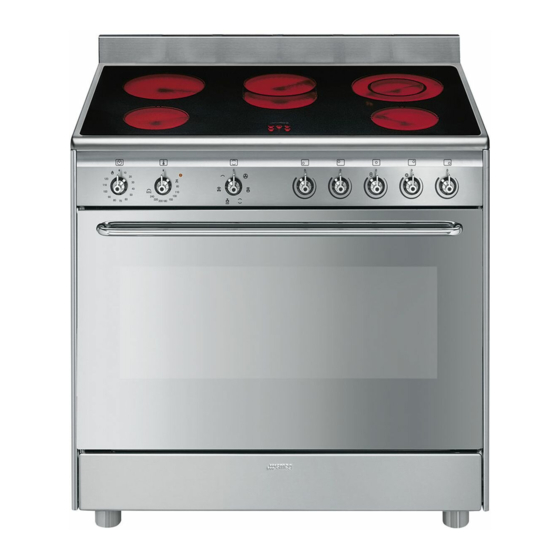
Page 5: Description
Description 2 Description 2.1 General Description 1 Backguard 5 Seal 2 Cooktop 6 Door 3 Control panel 7 Fan 4 Oven light Rack/tray support frame shelf... -
Page 6: Cooking Hob
Description 2.2 Cooking hob Zone Outside diameter (mm) Max. power draw (W)* Inside diameter (mm) Max. power draw (W)* 1200 2000 oval plate 2200 1400 2000 Power levels are approximate and can vary according to the pan used or the settings made. 2.3 Control panel 1 Minute minder timer knob 2 Temperature knob... -
Page 7: Other Parts
Description 2.4 Other parts 3 Indicator light The indicator light comes on to indicate that Shelves the oven is heating up. It turns off as soon as The appliance features shelves for it reaches the set temperature. It flashes positioning trays and racks at different regularly to indicate that the temperature set heights. -
Page 8: Available Accessories
Description 2.5 Available accessories Tray rack Some models are not provided with all accessories. Scraper To be placed over the top of the oven tray; for cooking foods which may drip. Deep tray Useful for cleaning the cooktop. Rack Useful for collecting fat from foods placed on the rack above and for cooking sweets, biscuits, etc. -
Page 9: Use
3 Use Improper use Risk of damage to surfaces 3.1 Instructions High temperature inside the oven • Do not cover the bottom of the oven during use cavity with aluminium or tin foil sheets. Danger of burns • If you wish to use greaseproof paper, place it so that it will not interfere with the •... -
Page 10: First Use
3.3 Using the accessories High temperature inside the oven during use Racks and trays Danger of fire or explosion Racks and trays have to be inserted into the side guides until they come to a complete • Do not spray any spray products near stop. -
Page 11: Using The Cooktop
Tray rack Switching on the cooking zones The tray rack has to be inserted into the tray. The appliance has cooking zones of In this way fat can be collected separately different diameters and power levels. from the food which is being cooked. Their positions and the edges of the heated area are shown by the markings on the glass. -
Page 12: Using The Oven
Practical advice for using the cooktop 3.5 Using the oven • The diameter of the base of the pan must Switching on the oven correspond to the diameter of the To switch on the oven: cooking zone. 1. Select manual cooking or set the cooking duration using the timer knob. - Page 13 Preheating stage Convection Cooking functions are always preceded by As the heat comes from above and a preheating stage, which allows the below at the same time, this system appliance to heat up to cooking is particularly suitable for certain temperature.
-
Page 14: Cooking Advice
3.6 Cooking advice Grill The heat coming from the grill General advice element gives perfect grilling results • Use a fan assisted function to achieve above all for thin and medium consistent cooking at several levels. thickness meat and, in combination •... - Page 15 • Use the oven tray on the first bottom shelf Advice for defrosting and proving to collect fluids produced by grilling. • Place frozen foods without their • Grilling processes should never last more packaging in a lidless container on the than 60 minutes.
-
Page 16: Cooking Information Table
Cooking information table Runner posi- Weight Temperature Food Function tion from the Time (minutes) (Kg) (°C) bottom Lasagne 3 - 4 Convection 220 - 230 45 - 50 Pasta bake 3 - 4 Convection 220 - 230 45 - 50 Roast veal Fan assisted/Fan forced 180 - 190... -
Page 17: Cleaning And Maintenance
Cleaning and maintenance 4 Cleaning and maintenance Cleaning the cooktop Smudges from aluminium-based pans can 4.1 Instructions be easily cleaned off with a cloth dampened in vinegar. Improper use After cooking, remove any burnt residues Risk of damage to surfaces with the scraper provided;... -
Page 18: Removing The Door
Cleaning and maintenance Weekly cleaning 4.3 Removing the door For easier cleaning, the door can be Clean and maintain the cooktop once a removed and placed on a tea towel. week using an ordinary glass ceramic cleaning product. Always follow the To remove the door proceed as follows: manufacturer’s instructions. -
Page 19: Cleaning The Door Glazing
Cleaning and maintenance 4.5 Removing the internal glass panes 3. To reassemble the door, put the hinges in the relevant slots in the oven, making sure For easier cleaning the door internal glass that grooved sections A are resting panes can be disassembled. completely in the slots. - Page 20 Cleaning and maintenance 4. Clean the external glass pane and the Removing racks/trays support frames panes previously removed. Use Removing the guide frames enables the absorbent kitchen roll. In case of sides to be cleaned more easily. This stubborn dirt, wash with a damp sponge operation should be performed each time and neutral detergent.
-
Page 21: Vapour Clean
Cleaning and maintenance 4.6 Vapour Clean • Pour approximately 40 cc of water into the tray. Make sure it does not overflow Vapour Clean is an assisted out of the cavity. cleaning procedure which facilitates the removal of dirt. Thanks to this process, it is possible to clean the inside of the oven very easily. - Page 22 Cleaning and maintenance Vapour Clean setting End of the Vapour Clean cycle 4. Open the door and wipe away the less 1. Turn the function knob to the symbol stubborn dirt with a microfibre cloth. the temperature knob to the symbol 5.
-
Page 23: Extraordinary Maintenance
Cleaning and maintenance 4.7 Extraordinary maintenance 4. Slide out and remove the light bulb. Replacing the oven light bulb Live parts Danger of electrocution • Unplug the appliance. The oven is fitted with a 40W light bulb. Do not touch the halogen light bulb directly with your fingers, but 1. - Page 24 Cleaning and maintenance the centre, then pull the oven seal. What to do if... The appliance does not work. • The circuit breaker is faulty: look in the fuse box and check that the circuit breaker is in working order. •...
-
Page 25: Installation
Installation 5 Installation General information This appliance may be installed next to 5.1 Positioning walls, one of which must be higher than the worktop, at a minimum distance of 50 mm Heavy appliance from the side of the appliance, as shown in Danger of crush injuries figures A and C relative to the installation classes. - Page 26 Installation Positioning and levelling Heavy appliance Risk of damage to the appliance • Insert the front feet first and then the rear ones. • After making the gas and electrical connections, screw on the four feet supplied with the appliance. B - Class 2 subclass 1 (Built-in appliance) The appliance must sit level on the floor to ensure stability.
- Page 27 Installation 3. Assemble the fastening bracket. Fastening to the wall The anti-tip devices must be installed in order to prevent the appliance tipping over. 1. Screw the wall fastening plate to the rear of the appliance. 4. Align the base of the hook on the fastening bracket with the base of the slot on the wall fastening plate.
- Page 28 Installation 5. Align the base of the fastening bracket 7. Move the bracket onto the wall and with the ground and tighten the screws to mark the position of the holes to be fix the measurements. drilled in the wall. 6.
- Page 29 Installation Wall fixing 4. Mark the wall in the position where the hole is to be drilled. 1. Turn the screw placed behind the cooktop near the gas connection. 5. Drill the hole and insert a wall plug. 2. Attach the chain to the cooker with the screw just removed.
-
Page 30: Electrical Connection
Installation 5.2 Electrical connection Assembling the upstand The upstand provided is an Power voltage integral part of the product. It must Danger of electrocution be fastened to the appliance prior to installation. • Have the electrical connection performed by authorised technical The upstand must always be positioned and personnel. - Page 31 Installation The appliance can work in the following Fixed connection modes: Fit the power line with an omnipolar circuit • 220-240 V 1N~ breaker in compliance with installation regulations. The circuit breaker should be located near the appliance and in an easily reachable position.
-
Page 32: For The Installer
Installation 5.3 For the installer • The plug must remain accessible after the installation is complete. Do not kink or trap the mains connection cable. • The appliance must be fitted according to the installation diagrams. • Do not attempt to turn or stress the threaded elbow on the manifold.