
Related Manuals for EVGA X299 DARK


Summary of Contents for EVGA X299 DARK
- Page 1 EVGA X299 DARK (151-SX-E299) User Guide EVGA X299 DARK Specs and Initial Installation - 1 -...
-
Page 2: Table Of Contents
Motherboard Specifications ....................- 6 - Unpacking and Parts Descriptions ..................- 8 - EVGA X299 DARK Motherboard LED reference ............. - 10 - EVGA X299 DARK Motherboard Component Legend ............. - 14 - PCIe Slot Breakdown (Skylake-X) ..................- 27 - M.2 and U.2 Slot Breakdown (Skylake-X) ................. - Page 3 Multifunction LED indicator .................... - 138 - POST Beep codes ......................- 142 - POST Port Debug LED ....................- 143 - POST Codes ......................- 144 - EVGA Glossary of Terms ....................- 149 - Compliance Information ..................- 152 - - 3 -...
-
Page 4: Before You Begin
24/7 number cruncher, and nothing you don't – a board that is as reliable as it is fast. The EVGA X299 Dark has all of the current gen top-tier component support, multiple M.2 slots, Intel... -
Page 5: Parts Not In The Kit
Monitor (Optional) Optical Drive EVGA assumes you have purchased all the necessary parts needed to allow for proper system functionality. For a full list of supported CPUs on this motherboard, please visit www.evga.com/support/motherboard Intentions of the Kit... -
Page 6: Motherboard Specifications
EVGA X299 DARK (151-SX-E299) Motherboard Specifications Size: EATX form-factor of 12 inches x 10.89 inches (304.8x276.7mm) Microprocessor support: Intel Socket 2066 Processor ® Operating Systems: Supports Windows 10 64bit System Memory support: Supports Quad-Channel DDR4 up to 4000MHz+ Skylake-X (OC), and 4133MHz+ Kaby Lake-X (OC). - Page 7 EVGA X299 DARK (151-SX-E299) 1x Intel i219V Gigabit (10/100/1000) Ethernet PHY ® 1x Intel i210AT Gigabit (10/100/1000) Ethernet MAC+PHY ® Ethernet Teaming Supported Power Functions: Supports ACPI (Advanced Configuration and Power Interface) Supports S0 (normal), S3 (suspend to RAM), S4 (Suspend to disk - depends...
-
Page 8: Unpacking And Parts Descriptions
EVGA X299 DARK (151-SX-E299) Unpacking and Parts Descriptions The following accessories are included with the EVGA X299 DARK Motherboard: - 8 -... - Page 9 EVGA X299 DARK (151-SX-E299) - 9 -...
-
Page 10: Evga X299 Dark Motherboard Led Reference
EVGA X299 DARK (151-SX-E299) EVGA X299 DARK Motherboard LED reference The EVGA X299 DARK Motherboard has several LEDs indicating power, connectivity, and activity. Below is the location of the LEDs and their function. - 10 -... - Page 11 EVGA X299 DARK (151-SX-E299) LED Legend Power Button PE1 Status/Mode CPU Malfunction Error Reset Button PE2 Status/Mode CPU FIVR Power Error Active BIOS ROM PE3 Status/Mode CPU Error U.2 Enable/OK PE4 Status/Mode +5V PSU Power Skylake-X Only Memory Status PE5 Status/Mode...
- Page 12 EVGA X299 DARK (151-SX-E299) 9. PCIe LED for PE1. The LED will remain off when this PCIe slot is disabled or unpopulated. a. WHITE: PE1 slot can be used with installed CPU. b. GREEN: PE1 device present and detected. 10. PCIe LED for PE2. The LED will remain off when this PCIe slot is disabled or unpopulated.
- Page 13 EVGA X299 DARK (151-SX-E299) ii. Rather than staying a solid white for “ON,” some devices will blink when detected/active. This is specific to some devices. b. GREEN: PM1 device present and detected. 17. CATERR a. CATERR stands for Catastrophic Error on the processor.
-
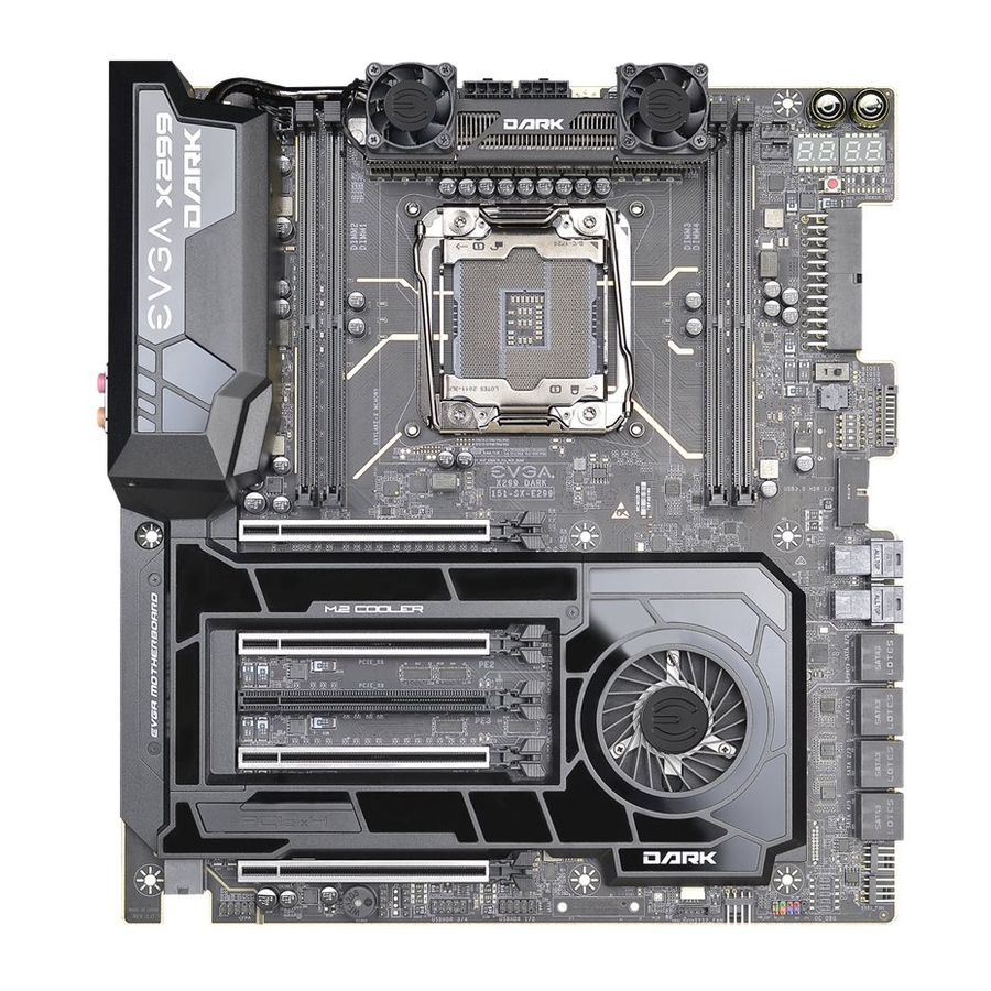
Page 14: Evga X299 Dark Motherboard Component Legend
EVGA X299 DARK (151-SX-E299) EVGA X299 DARK Motherboard Component Legend The EVGA X299 DARK Motherboard with the Intel X299 and PCH Chipset. ® Figure 1 shows the motherboard and Figure 2 shows the back panel connectors FIGURE 1. X299 DARK Motherboard Layout... - Page 15 EVGA X299 DARK (151-SX-E299) Component Legend CPU Socket 2066 M.2 Socket 3 Key-M 110mm USB 2.0 Headers Intel X299 PCH (Southbridge) M.2 Socket 3 Key-M 80mm VROC Header PWM Fan Headers (1 amp) PCI-E Slot x16/x8 Front Panel Audio Connector...
- Page 16 EVGA X299 DARK (151-SX-E299) Figure 2. Chassis Rear Panel Connectors I/O Hub PS/2 (Keyboard) BIOS/CMOS Reset M.2 Key-E Vertical Header USB 3.0 Intel i219 NIC Optical Out USB 3.1 type A Intel i210 NIC Analog Audio Jacks USB 3.1 type C...
- Page 17 EVGA X299 DARK (151-SX-E299) Component Legend Descriptions 1. CPU Socket 2066 This is the interface for the Central Processing Unit (CPU), and supports Core ™ X-Series i5, i7 and i9 models compatible with the Intel LGA2066 Socket, ® based on Skylake-X and Kaby Lake-X architecture.
- Page 18 EVGA X299 DARK (151-SX-E299) installation guide on Page 34. Kaby Lake-X supports up to 32GB (2x16GB) up to 4000MHz+. 32GB and larger RDIMM modules are *NOT* supported on this platform. Kaby Lake-X only supports memory in DIMM slots 3 and 4.
- Page 19 EVGA X299 DARK (151-SX-E299) 8. Supplemental PCIe 6-pin Power Connector There is a 6-pin PCIe connector at the bottom of the motherboard (See Page 48 for more specifics to the connector itself, and associated wiring/pinouts). This connector provides dedicated power to the PCIe x16 slots, augmenting the +12V power provided by the 24-pin and the GPU directly.
- Page 20 EVGA X299 DARK (151-SX-E299) 13. M.2 Socket 3 Key-M 80mm (PM2) M.2 is an SSD standard, which uses up to four PCIe lanes and utilizes Gen3 speeds. Most popularly paired with NVMe SSDs, this standard offers substantially faster transfer speeds and seek time than SATA interface standards.
- Page 21 EVGA X299 DARK (151-SX-E299) Using this slot will have *NO EFFECT* on the bandwidth or throughput of the x16 slots used for SLI because this slot uses only PCH bandwidth. 18. Power Button This is an onboard power button, and may be used in place of, or in conjunction with, a front panel power button wired to the board.
- Page 22 USB 3.1 Type-A (found on the I/O Hub) shares the power limit of USB 3.0 at 900mA @ 5V. Whereas USB 3.1 Type-C (also found on the IO Hub) has a power limit of 3000mA (3A) @ 5V. USB 3.1 on the X299 Dark does not support USB PD protocol.
- Page 23 BIOS failures, bad BIOS flashes, BIOS corruption, etc. This feature also allows EVGA to work with end-users if something happens to render the BIOS chip unusable or a BIOS update is needed for CPU compatibility; rather than...
- Page 24 This allows you to swap between three physically different BIOS chips. This also makes it substantially easier to hotflash a BIOS if needed. If instructions are needed for hotflashing a BIOS, please contact EVGA Customer Service (Page 130 for contact info).
- Page 25 EVGA X299 DARK (151-SX-E299) button provides a much faster means of resetting than the previous method of removing power from the board, removing the CMOS battery, and discharging power to the board. In rare occasions the older method can help; pressing the clear CMOS button will normally allow you and your system back into the default BIOS.
- Page 26 EVGA X299 DARK (151-SX-E299) Card Slots The X299 DARK features five x16 PCIe slots, one x4 PCIe slot, one Socket 3 Key- M M.2 110mm PM1 (backwards compatible with Key-M 80mm, 60mm, and 42mm), one Socket 3 Key-M M.2 80mm PM2 (backwards compatible with Key-M 60mm, and 42mm), and one vertical Socket 1 Key-E M.2.
-
Page 27: Pcie Slot Breakdown (Skylake-X)
EVGA X299 DARK (151-SX-E299) PCIe Slot Breakdown (Skylake-X) ™ PCIe Lane Distribution (Core i9-79xx, 44 Lane Processors) PE1 – x16 (Gen3, x16 lanes from CPU, x8 shared with PE2) PE2 – x16 (Gen3, x8 lanes from CPU, shares 8 of PE1’s 16 lanes) ... -
Page 28: And U.2 Slot Breakdown (Skylake-X)
EVGA X299 DARK (151-SX-E299) M.2 and U.2 Slot Breakdown (Skylake-X) ™ PCIe Lane Distribution (Core i9-79xx, 44 Lane Processors) U.2(PU1) x4 PCIe Gen 3 lanes from CPU o Must be enabled in BIOS, which disables M.2 110mm U.2(PU2) x4 PCIe Gen 3 lanes from CPU ... -
Page 29: Pcie Slot Breakdown (Kaby Lake-X)
EVGA X299 DARK (151-SX-E299) PCIe Slot Breakdown (Kaby Lake-X) ™ PCIe Lane Distribution (Core i5-76xx and i7- 77xx, 16 Lane Processors) PE1 – x16 (Gen3, x16 lanes from CPU, x8 shared with PE2) o PE1 can be disabled completely to run two M.2 drives PE2 –... -
Page 30: And U.2 Slot Breakdown (Kaby Lake-X)
EVGA X299 DARK (151-SX-E299) M.2 and U.2 Slot Breakdown (Kaby Lake-X) ™ PCIe Lane Distribution (Core i5-76xx and i7- 77xx, 16 Lane Processors) U.2(PU1) x4 PCI-E Gen 3 lanes (Shared with M.2 Key-M 110mm PM1) o Cannot be enabled when SLI is used o This U.2 has two requirements to enable:... -
Page 31: Preparing The Motherboard
EVGA X299 DARK (151-SX-E299) Preparing the Motherboard Installing the CPU Note: EVGA strongly recommends that you completely disconnect AC power from ™ your power supply prior to changing your CPU type (e.g. uninstalling a Core ™ X-Series i7 Kaby Lake-X CPU prior to installing a Core X-Series i9 Skylake- X CPU). - Page 32 EVGA X299 DARK (151-SX-E299) 3. Pull the socket levers back and gently lift the load plate to open the socket. Make sure to avoid touching or dropping items into the socket; otherwise, you may damage the board socket and/or CPU pins, which may void your warranty.
-
Page 33: Installing The Cpu Cooling Device
EVGA X299 DARK (151-SX-E299) 6. Carefully lock the right lever back into place by lowering it down to the hook, then push the lever towards the socket and down under the hook. 7. Carefully lock the left lever back into... -
Page 34: Installing System Memory
As shown in the chart above, Kaby Lake-X CPUs require DIMMs installed in Slot DIMM3 and/or Slot DIMM 4 to boot normally. The X299 Dark will still boot normally with a Kaby Lake-X CPU if memory DIMMs are also installed in Slots 1 or 2. Neither system operation nor overclocking will be affected;... -
Page 35: Installing The I/O Shield And I/O Cover
M.2 Key-E device on Page 43. The X299 Dark also includes an I/O cover. This I/O cover adds a unique appearance to the I/O area of the motherboard and directs the airflow for optimal cooling to M.2 Socket 3 devices. -
Page 36: Installing The Motherboard
EVGA X299 DARK (151-SX-E299) Installing the Motherboard Installing the motherboard into a system case depends on several factors: whether you are replacing an existing motherboard, whether you are building a new PC, and the type of chassis that will house your PC components. You must first determine if it would be easier to secure the motherboard to the chassis or if it would be easier to install other components prior to this step. -
Page 37: Securing The Motherboard Into A System Case
6. See the picture below for a zoomed-in view of a hole to place over a standoff, as well as the locations of standoff holes for the X299 DARK. - 37 -... - Page 38 EVGA X299 DARK (151-SX-E299) 1. All safe locations to secure the board to a standoff are circled in white. 2. Keep in mind that when the screws are installed, but not fully tightened, the motherboard should have 1-2mm of movement; this can help when mounting cards or tight-fits with other components.
-
Page 39: Installing M.2 Devices
EVGA X299 DARK (151-SX-E299) Installing M.2 devices Installing M.2 Key-M Socket 3 Devices Securing an M.2 device to the motherboard requires a few extra steps compared to other current drive or slot-based connectors. M.2 devices used on this motherboard - Socket 3 (for SSDs) and Socket 1 (for WiFi/Bluetooth) –... - Page 40 4. For each M.2 Key-M device you plan to install, add one thermal pad – included with the X299 Dark accessories – to the outlined area below. This will assist with cooling your M.2 Key-M device.
- Page 41 EVGA X299 DARK (151-SX-E299) 6. Gently push the M.2 device down on the raised end. There will be some tension - this is normal - then use the screw you removed in Step 2 to secure the device. Below, you can see that the contacts will be nearly invisible when the device is properly seated and the copper mounting semi-circle is partially visible around the screw.
-
Page 42: Incorrect M.2 Installation Example
EVGA X299 DARK (151-SX-E299) Incorrect M.2 Installation Example: *NOTE* This is one of the most common examples of an incorrect installation of an M.2 device. Do not intentionally attempt this, or complete your installation with this example. Doing so could cause damage to the device or the M.2 port. -
Page 43: Installing M.2 Key-E Socket 1 Devices
I/O ports. Please see Page 16 to locate the slot. The X299 Dark accessories include an M.2 Key-E adapter, but do not include an M.2 Key-E Socket 1 device, which must be purchased separately. You can find a list of officially supported M.2 Key-E devices on Page 46. - Page 44 M.2 Key-E slot will be located here: Note: The M.2 Key-E slot on the X299 Dark is a vertical-angle slot, requiring a bracket to stabilize your Key-E device. This bracket is included with the X299 Dark accessories and featured in the following images; however, the Key-E device pictured below is not included with the X299 Dark and must be purchased separately.
-
Page 45: Tested Cpu And Memory
4.0 GHz / 4.2 GHz (Boost) This list of tested CPUs is accurate as of the time of print. For a full list of tested CPUs and Memory, including updates, go to https://www.evga.com/support/motherboard/ and select the EVGA X299 Dark from the list. - 45 -... -
Page 46: Tested M.2 Key-M
EVGA X299 DARK (151-SX-E299) Tested U.2 U.2 (SSD): Brand Part Number Size Interface Intel 750 SSDPE2MW400G4 400GB U.2 NVME w\Cable Intel 750 SSDPE2MW400G4 400GB U.2 NVME w\Cable Tested M.2 Key-M M.2 Key M (SSD) : Brand Part Number Size Interface... -
Page 47: Connecting Cables
Connecting Cables Note: the following images do not necessarily represent the physical orientation of their respective headers on the EVGA X299 Dark. Rather, these graphical representations are designed to provide a basic physical footprint and the cable pinouts for each component. - Page 48 Firmly plug the power supply cable into the connector and make sure it is secure. The 24-pin Power Connector may be standard or right-angled depending on your motherboard model. The X299 Dark motherboard uses a right-angle 24pin ATX connector. 6-pin PCIe...
- Page 49 EVGA X299 DARK (151-SX-E299) EPS 8-pin 12V Power (PWR , the 8-pin ATX 12V power connection(s), is used to provide EPS PWR 8P power to the CPU. Align the pins to the connector and press firmly until seated. The secondary EPS, if present, is optional for improved overclocking. Please remember to make sure that the tab on the EPS socket is aligned with the release clip on the cable.
-
Page 50: Front Panel Header
EVGA X299 DARK (151-SX-E299) Front Panel Header The front panel header on this motherboard is used to connect the following four cables: PWRLED Attach the front panel power LED cable to these two pins of the connector. The Power LED indicates the system’s status. When the system is powered on, the LED will be on. -
Page 51: Fan Header
EVGA X299 DARK (151-SX-E299) Fan Header This motherboard line only has 4-pin fan headers, which are backwards compatible with 3-pin fan connectors. Fans may be controlled by PWM or DC controls. The headers have an absolute safe power limit of 2 Amp @ 12 Volts (24 Watts). -
Page 52: Usb Headers
EVGA X299 DARK (151-SX-E299) USB Headers The motherboard contains 1x 19-pin internal header connectors onboard that can be used to connect an optional external bracket containing up to two (2) USB 3.0 ports. Secure the bracket to either the front or rear panel of your chassis (not ... - Page 53 EVGA X299 DARK (151-SX-E299) The motherboard contains 2x 9-pin internal header connectors onboard that can be used to connect an optional external bracket containing up to four (4) USB 2.0 ports. Secure the bracket to either the front or rear panel of your chassis (not ...
-
Page 54: Front Panel Audio Header
EVGA X299 DARK (151-SX-E299) Front Panel Audio Header Front panel audio supports HD Audio for stereo/gaming headphones or 2.1 speakers, and a Mic. - 54 -... - Page 55 EVGA X299 DARK (151-SX-E299) Drive Headers (SATA/ U.2) SATA 3/6Gbit/s is the current standard for HDD/SSD/Optical interface. These cables are the data interconnect for the motherboard. Your HDD/SSD/Optical interface will still require a separate power connection from your power supply.
-
Page 56: Onboard Buttons
EVGA X299 DARK (151-SX-E299) Onboard Buttons These onboard buttons include RESET, POWER and Clear CMOS. These functions allow you to easily turn on/off the system, reset the system or clear the CMOS. Clear CMOS Button The motherboard uses CMOS RAM to store set parameters. -
Page 57: First Boot
EVGA X299 DARK (151-SX-E299) First Boot When you power the system on for the first time (or after a BIOS update/reset) it may take a little longer than expected, and follow with a pause and message on the screen reading “BIOS Checksum error, Press F2 to continue or F12 to enter the BIOS.”... - Page 58 EVGA X299 DARK (151-SX-E299) HDD/SSD/M.2/U.2 Setup Next, click “Boot” from the menu list at the top. “Boot Option #1” should show the device that you intend to install your operating system. If you are using a standard SSD/HDD connected to a SATA port, but the device is not present in the Boot Option #1 menu, scroll down to “UEFI Hard...
-
Page 59: Ssd, Pcie Ssd, And Nvme Ssd Installation Steps
EVGA X299 DARK (151-SX-E299) M.2 SSD, PCIe SSD, and NVMe SSD Installation steps M.2 is a versatile card module form factor that uses multiple connecter types to connect many types of devices, such as WiFi or SSDs, in a very small and power efficient package. - Page 60 EVGA X299 DARK (151-SX-E299) 2. After reviewing your SSD’s instructions and its respective Physical installation instructions above, power on the PC and enter the BIOS/UEFI by pressing the F2 key repeatedly. 3. Once in BIOS/UEFI, navigate to the “BOOT” section. Then go down to the “CSM Configuration”...
-
Page 61: Internal Raid Controller
EVGA X299 DARK (151-SX-E299) Internal RAID Controller This section introduces RAID, RAID levels, and the basics of the controller integrated into the PCH. It covers the basics of what RAID does, how RAID works, and why you may or may not want to use RAID. - Page 62 EVGA X299 DARK (151-SX-E299) its quality, and many other factors; but the number should give you a ballpark estimate on what to expect as a final capacity once formatted. Please see below for examples of what to expect when you build an array of each type.
- Page 63 EVGA X299 DARK (151-SX-E299) one drive fails, the array fails. It MAY be possible to recover the data but that usually requires a data recovery service, which is not guaranteed and is usually very expensive. RAID0 is typically only limited by the controller; however, you will get severely diminishing performance returns after 4 drives.
- Page 64 EVGA X299 DARK (151-SX-E299) RAID 0 (4 Drive) P-DRIVE1 P-DRIVE2 P-DRIVE3 P-DRIVE4 P-DRIVE1 P-DRIVE2 P-DRIVE3 P-DRIVE4 DATA-A DATA-B DATA-C DATA-D DATA-A DATA-B DATA-C DATA-D DATA-ABCD DATA-ABCD P-DRIVE1 P-DRIVE2 P-DRIVE3 P-DRIVE4 P-DRIVE1 P-DRIVE2 P-DRIVE3 P-DRIVE4 DATA-A DATA-B DATA-C DATA-D DATA-A DATA-B...
- Page 65 EVGA X299 DARK (151-SX-E299) The Bad- RAID1 is not a storage capacity-friendly array, because the capacity will be limited to 1 drive. o Due to the capacity available on modern drive solutions, this issue may not be as significant as it once was.
- Page 66 EVGA X299 DARK (151-SX-E299) Similar to RAID1, or any other current type of array with fault tolerance, a RAID5 array is still usable even while it is experiencing a missing or failed drive resulting in the array functioning in a degraded state. Performance will suffer in a degraded state until the missing drive is replaced and the software rebuild process is completed.
- Page 67 EVGA X299 DARK (151-SX-E299) L-DRIVE = ≃ 3TB RAID 5 (4 Drive) P-DRIVE1 P-DRIVE2 P-DRIVE3 P-DRIVE4 P-DRIVE1 P-DRIVE2 P-DRIVE3 P-DRIVE4 P-DRIVE1 P-DRIVE2 P-DRIVE3 P-DRIVE4 DATA-A DATA-B DATA-C DATA-A DATA-A DATA-B DATA-C DATA-A DATA-A DATA-B DATA-C DATA-A DATA-B DATA-C DATA-A DATA-B...
- Page 68 L-Drive = DATA-AB L-Drive = DATA-AB While the X299 DARK controller will support a four or six drive RAID10 array, RAID10 can scale indefinitely provided the controller supports more drives. Every pair of drives adds an additional mirrored node, which increases the theoretical number of failures the array can suffer before a loss of data occurs.
- Page 69 EVGA X299 DARK (151-SX-E299) RAID 10 (6 Drive) L-DRIVE = ≃ 3TB In the case of a drive P-DRIVE1 P-DRIVE2 P-DRIVE3 P-DRIVE4 P-DRIVE5 P-DRIVE6 failure, the array P-DATA-A P-DATA-A P-DATA-B P-DATA-B P-DATA-C P-DATA-C controller will notify you. When you replace a...
- Page 70 EVGA X299 DARK (151-SX-E299) RAID0+1 : RAID0+1 is a form of nested RAID that was widely used on previous generation boards. Although the X299 series motherboards do not use this type of array, it is listed here to show the improvements made by RAID10, and to clear up a common misperception that RAID0+1 and RAID10 are the same.
- Page 71 L-Drive = DATA-AB L-Drive = DATA-AB Motherboard controllers that support RAID0+1 (such as on older generation EVGA motherboards) will generally support 4 or 6 drive arrays of this type; other controllers can allow this array type to scale indefinitely. Each pair of drives adds to the drive count for the stripes and increases the theoretical volume of failures the array can suffer before a loss of data occurs.
- Page 72 EVGA X299 DARK (151-SX-E299) RAID 0+1 (6 Drive) L-DRIVE = ≃ 3TB As you can see, the P-DRIVE1 P-DRIVE2 P-DRIVE3 P-DRIVE4 P-DRIVE5 P-DRIVE6 difference between RAID0+1 and RAID10 DATA-A DATA-B DATA-C DATA-A DATA-B DATA-C is significant when looking at how data is...
- Page 73 EVGA X299 DARK (151-SX-E299) Which types of RAID can I use with my setup? 1 Drive – No RAID arrays are supported 2 Drives – RAID0 for speed (do regular backups) or RAID1 for data protection. 3 Drives – RAID0 for speed (do regular backups) or RAID5 for speed and protection.
- Page 74 EVGA X299 DARK (151-SX-E299) In the “SATA Mode Selection” at the top, the default will be AHCI. Click on the arrow to the right side of AHCI or navigate to it with your keyboard and press “Enter” to open the pulldown menu. Select RAID from the list.
- Page 75 EVGA X299 DARK (151-SX-E299) Once in the RAID controller, you will see a list of all detected drives and a “Create RAID Volume” button. To begin, click on “Create RAID Volume” or navigate to the button and hit “Enter.” Choose a name for the volume. The controller allows up to 15 characters; you can use numbers and letters, but not special characters.
- Page 76 EVGA X299 DARK (151-SX-E299) Next, select your intended array type. This can be done by either clicking on the down arrow and clicking on the RAID level you want, or pressing the enter key and using the down arrow to select the RAID level and pressing Enter again. Please see the top half of Page 73 for a quick reference on different RAID levels and RAID types based on your total number of drives.
- Page 77 EVGA X299 DARK (151-SX-E299) Strip size (also called “block size” in other controllers) can be selected manually at 16k, 32k, 64k, or 128k. The controller will determine the default strip size after looking at your drives and array type. Although there are some limited instances where this must be set manually, it is highly recommended to leave this at default.
- Page 78 EVGA X299 DARK (151-SX-E299) If your array will be your boot drive, the operating system will normally detect the array and see it as a single drive (this is expected), it *MAY* detect it as a RAID array; either way, the OS installation will show the size of the array, not a single drive, and allow you to install the OS to the array without any further steps.
- Page 79 EVGA X299 DARK (151-SX-E299) Non-RAID Physical Disks list will display any remaining drives on the controller, whether it is a random storage drive, a boot drive, or a replacement drive installed to replace a failed unit. For this example, you will see a degraded array and a “Non-RAID Physical Disk,”...
- Page 80 EVGA X299 DARK (151-SX-E299) Next, you will see a list of all attached HDD/SSDs that can be used to rebuild the array. Select the disk, then click on it or press enter. Once the process has started you will see the status change to “Rebuilding.”...
- Page 81 EVGA X299 DARK (151-SX-E299) IRST (Intel ® Rapid Storage Technology) The IRST is the software front-end for the Intel SATA controller. It is recommended ® to install the IRST drivers after installing the Intel Chipset Drivers – the main ®...
- Page 82 EVGA X299 DARK (151-SX-E299) SATA will be selected by default. PCIe primarily refers to PCIe / M.2 based NVMe drives; the same basic steps do apply to both, however. Select SATA, and “Real-time protection (RAID1).” Then, click Next at the bottom of the window.
- Page 83 EVGA X299 DARK (151-SX-E299) - 83 -...
- Page 84 EVGA X299 DARK (151-SX-E299) In the Advanced tab, you can select the option to “Initialize Volume,” which will occur after the array is created. If the array is not initialized now, it can be initialized later in “Disk Management.” See Page 91 for Disk Management instructions.
- Page 85 EVGA X299 DARK (151-SX-E299) Review the summary provided on the confirmation screen. If you are unsure about any selections made, click the “Back” key and make your corrections. When ready, click “Create Volume” at the bottom. This typically takes between a few seconds to a couple minutes depending on the size and complexity of the volume.
- Page 86 EVGA X299 DARK (151-SX-E299) Once you click the OK button on the RAID creation window you will be brought back to the main window, “Status” tab. If the option to initialize was selected, the initialization status will be shown below, circled in red.
- Page 87 EVGA X299 DARK (151-SX-E299) Repairing an array within IRST This section of the guide will illustrate how to repair a degraded array from within the IRST. For purposes of this guide, we are repairing a degraded RAID 1 array using a third drive plugged into the controller, but not currently in use.
- Page 88 EVGA X299 DARK (151-SX-E299) The “Manage” tab shows the array specifically, and not just the controller as a whole. Next to “Status: Degraded,” left-click the hyperlink labeled “Rebuild to another disk.” This will bring a pop-up window over the IRST showing a list of attached drives that...
- Page 89 EVGA X299 DARK (151-SX-E299) Select the drive you wish to use for the repair and click the “Rebuild” button. - 89 -...
- Page 90 EVGA X299 DARK (151-SX-E299) The rebuild process will begin. As with any RAID array with Fault Tolerance, the rebuilding time depends on several factors, such as array size, array type, CPU, etc. You will then see the Rebuild % status in the Manage tab. Once repairs are complete, the array will update to “Status: Normal.”...
- Page 91 EVGA X299 DARK (151-SX-E299) Partitioning and Formatting a drive Once you have created your array, either from UEFI or from IRST, you will not initially see your array in “This PC.” This is expected, because even though you have created the array, you have not yet prepared the array to be used.
- Page 92 EVGA X299 DARK (151-SX-E299) After “Disk Management” loads, you’ll see a pop-up to Initialize Disk if you’ve added a new drive or created a new array. Generally, it’s recommended to select “GPT,” unless you need backwards compatibility with an old OS or PC. When you’ve made your choice, click “OK.”...
- Page 93 EVGA X299 DARK (151-SX-E299) Before you can assign a drive letter to a drive or array, the initialized disk must be partitioned. If you are following this guide and just initialized your drive or array, the New Simple Volume Wizard will automatically pop-up.
- Page 94 EVGA X299 DARK (151-SX-E299) Leave the size at default to create a partition using the entire volume of disk space, then click “Next.” Select the drive letter you want to represent this drive, then click “Next.” Note: The drive letter does NOT have to be a consecutive letter with previous drive(s).
- Page 95 EVGA X299 DARK (151-SX-E299) After the quick format is completed, you will see the last Window of the wizard, a summary of the process, then click “Finish.” The drive is now usable. To confirm, go back to File Explorer in Windows. Click on “This PC” and check the drives section.
-
Page 96: Fan Header Dc And Pwm Setup
EVGA X299 DARK (151-SX-E299) Fan Header DC and PWM setup This motherboard supports 4-pin PWM and DC fans. All of the fans can be set to a static voltage manually. The upper two (2) fan headers (see Pages 14 and 15, component number 3) are PWM-controlled, whereas the remaining fans (see Pages 14 and 15, component number 4) are controlled by either DC (Direct Current) or PWM. - Page 97 EVGA X299 DARK (151-SX-E299) Once into the H/W Monitor section, you can see the temperature monitors across the top. Below the monitors are the two (2) PWM fans: CPU1_FAN, CPU2_FAN, and CHA_FAN. The PWM fans are set to “Smart,” which means the PWM controller is using a Smart curve for fan controls.
- Page 98 EVGA X299 DARK (151-SX-E299) First, choose the temperature monitor the PWM controller will use to monitor for its temp information. It’s recommended to tie the fan control to the CPU, which is predominantly the most important temperature in the system. The exception is when you are pushing memory overclocks HARD with 64GB of RAM installed, which may cause PWM temps to be a concern;...
- Page 99 When monitoring temperatures vs. fan speed, you may notice a variance in ramp up/down temps; this is due to a function EVGA hardcodes into the BIOS called Hysteresis. Hysteresis builds in a buffer to control fan speed behavior. This feature prevents a constant ramp up/down from happening when your system sits exactly at the temp you set for SMART fan controls.
-
Page 100: Setting Up Sli And Physx
1. Physically install your graphics cards, then install a SLI bridge; examples include a Flexible bridge (included with this motherboard), an EVGA Pro Bridge, or an EVGA HB Bridge. Current NVidia graphics drivers support 400 Series Fermi cards up through GTX 1080 Ti and Titan XP cards. - Page 101 EVGA X299 DARK (151-SX-E299) 2. After the cards are installed, have power connected, and the SLI bridge attached, boot into Windows. The graphics driver will normally identify the cards and automatically configure the driver. If not, then you may need to reinstall the driver.
- Page 102 EVGA X299 DARK (151-SX-E299) 3. Once you have verified there are no detection/driver installation issues with the cards, you can enable SLI. Right-click on the desktop and select “NVIDIA Control Panel” (“NCP”). Next, select “Configure SLI, Surround, PhysX” under the “3D Settings”...
- Page 103 PhysX card serves no purpose. If “Yes,” then the next step is to see if your GPU has a high usage rate while playing normally. Use a program like EVGA Precision XOC to monitor the GPU usage of all current video cards. If the GPU is consistently over 75% usage, the GPU usage occasionally maxes out and the frame rate drops in moments of intense action, then dedicating a card may be beneficial.
-
Page 104: Creative Labs Sound Blaster Pro Studio
EVGA X299 DARK (151-SX-E299) Creative Labs Sound Blaster Pro Studio The X299 Dark uses a 5.1 Creative Labs CA0132 audio controller. This section will cover installation of the controller (in Windows 10) and the basic configuration options that are available in the software. - Page 105 EVGA X299 DARK (151-SX-E299) You’ll have one last prompt to go back and make any last minute changes before proceeding with the installation. When ready, click “Install” to begin the installation with the selected options. Once the install process is complete, click “Finish.” A final window will pop-up informing you that the installation is complete and prompt you to reboot to complete the installation.
- Page 106 EVGA X299 DARK (151-SX-E299) The below images are all composites, showing the tooltips for multiple buttons and menus on screen at the same time to reduce picture clutter; your experience will differ, because you will need to hover the mouse pointer over each button and panel individually to see the same tooltips in the Sound Blaster Recon 3Di Control Panel.
- Page 107 EVGA X299 DARK (151-SX-E299) amplifies it. A subwoofer is not necessary, but the quality of your audio equipment will determine how far you can raise the slider before the audio becomes distorted “Crossover Frequency” should be adjusted based on your audio equipment. This setting controls the frequency cutoff for speakers and subwoofer.
- Page 108 EVGA X299 DARK (151-SX-E299) The next section is “CrystalVoice,” which covers microphone controls. Using the image to the right, the pulldown menu displays the current default recording, and allows you to switch between other connected recording devices, if present. The upper-right button, outlined in red, allows you to select whether the recording device is a Rear Microphone or Line-In device.
- Page 109 EVGA X299 DARK (151-SX-E299) Mic Recording Volume adjusts the level of volume that will be picked up by the mic – including background noise – and played back to listeners or captured by a recording. This setting is the easiest way to make quick adjustments to your voice level.
- Page 110 Needless to say, this feature is designed to have fun with the person to whom you are speaking. Neither Creative nor EVGA guarantees that you will actually sound like any of these options. - 110 -...
- Page 111 EVGA X299 DARK (151-SX-E299) Scout mode is a setting specifically for video games and, more specifically, first-person shooters. Enabling Scout Mode will reduce the sound from music, voices, explosions, etc. and amplify the sounds of footsteps, brush, and ambient noises without raising the overall volume.
- Page 112 EVGA X299 DARK (151-SX-E299) The “Speaker/Headphones” section will provide configuration options for Speakers in a 2.0/2.1, 5.1 Surround, or Headphones. Please review the Component Legend on Page 16 to make sure you connect your audio device(s) to the correct port(s).
- Page 113 EVGA X299 DARK (151-SX-E299) To determine if your speakers are full-range or not, you must look at the minimum frequency response of your speakers. The concern is not the high-end of the frequency response, but rather the low-end. As noted above, if your speakers are not rated for a minimum of 20Hz, then they are not full-range speakers.
- Page 114 EVGA X299 DARK (151-SX-E299) full-range speakers in your setup, or 2) you are using a receiver or speaker system that prefers to handle the low frequency crossover at the receiver or speaker system, rather than using the Pro Studio to configure the crossover settings for low frequencies.
- Page 115 EVGA X299 DARK (151-SX-E299) In 5.1 mode, you can toggle the center channel, subwoofer, and rear satellite speakers on and off from this menu. If any of the satellites are disabled, the sound readjusts to ensure you receive full sound, albeit balanced through the selected speakers.
- Page 116 EVGA X299 DARK (151-SX-E299) In the lower section there is an option for “Full-Range” speakers. You must set the front speakers to Full-Range before the Full-Range option becomes available for Surround speakers. If you are unsure if your speakers are full-range or not, please see the previous section on Page 113.
- Page 117 EVGA X299 DARK (151-SX-E299) On a system that does not use full-range speakers, this is a crucial setting for ensuring that your speaker system correctly plays low frequencies. The default frequency is set to 80Hz, but your system may need adjustment.
- Page 118 EVGA X299 DARK (151-SX-E299) As with any speaker or microphone setting, your audio equipment will have a significant effect on audio quality and effectiveness of multiple settings. For example, some microphones already equip some degree of noise or echo cancellation and do not benefit further from Creative’s CrystalVoice options.
- Page 119 EVGA X299 DARK (151-SX-E299) The Mixer section is where you can control volume levels, balance, input jacks, stereo volume for all input and output devices, and master volume for all sections. The top setting is “Speakers,” which is the Windows main volume;...
- Page 120 EVGA X299 DARK (151-SX-E299) The “Equalizer” section provides a software-based EQ with several preset built-in tools to manually to make custom balances for any type of music, game, or movie. By default, the equalizer is disabled, leaving all frequency bands at a median.
- Page 121 EVGA X299 DARK (151-SX-E299) Click on the “EQ” button in the upper- left corner to enable the “EQ” functionality. Once enabled, the pulldown menu for EQ presets and manual controls becomes available. The default EQ setting is “Flat,” which means no specific optimization.
- Page 122 EVGA X299 DARK (151-SX-E299) The final tab of the Sound Blaster Audio Suite is the “Advanced Features” tab. This tab has the singular option to enable or disable “Play stereo mix to digital output”. Check this box to enable output through SPDIF and speaker simultaneously.
- Page 123 EVGA X299 DARK (151-SX-E299) Using the E-LEET Software Suite EVGA E-LEET is a monitoring and tuning software designed for EVGA motherboards, which is available on the driver DVD and the EVGA website at www.evga.com/E-LEET After installation, E-LEET will launch directly...
- Page 124 EVGA X299 DARK (151-SX-E299) The next tab is “Monitoring,” which is an overview of temperatures and voltages in real-time. Please note that all readings on this page are pulled from motherboard sensors, and can change at any time. Temperatures and voltages are measured at fixed intervals, which can often make the readings appear to jump back and forth.
- Page 125 EVGA X299 DARK (151-SX-E299) The Options tab is for managing your E- LEET profiles. You can save overclock profiles made in the previous section, as well as selecting an option to load a profile at boot. Use care, however, when setting a profile to load on startup;...
- Page 126 EVGA X299 DARK (151-SX-E299) The final section is “Voltages,” which provides a level of voltage control similar to what is available in the BIOS. Using the right image, you’ll notice that there are options for multiple voltages, and two options for your Vcore and Vmesh: Adaptive and Override voltages.
- Page 127 LEET will open the pulldown to the currently detected voltage. Please be careful when adjusting voltages, as there are risks to running electronics out of spec. Although EVGA warranties overclocking, other components are manufactured by different brands (i.e. RAM and CPU), which may have different policies towards overclocking.
-
Page 128: Installing Drivers And Software
7, and 8/8.1 through the ASMedia SATA controller. The kit comes with a CD that contains utilities, drivers, and additional software. The CD that has been shipped with the EVGA X299 Dark Motherboard contains the following software and drivers: Chipset Drivers ... -
Page 129: Warranty And Overclocking
Of course, there are some limitations to our warranties. If an EVGA motherboard or graphics card sustains physical (i.e. damage to the PCB or component due to slippage with a hand tool) or liquid damage, the warranty is void. -
Page 130: Troubleshooting
FOR ANY AND ALL INSTANCES WHERE YOU THINK YOU MAY NEED A REPLACEMENT BIOS CHIP, PLEASE CALL CUSTOMER SERVICE IMMEDIATELY. DO NOT ATTEMPT TO REPLACE THE BIOS CHIP WITH ONE **NOT** SUPPLIED BY EVGA, AS EVGA CANNOT OTHERWISE GUARANTEE COMPATIBILITY. CONTACT INFORMATION, HOURS, AND LOCATIONS FOR ALL EVGA CUSTOMER SUPPORT OFFICES CAN BE FOUND HERE: http://www.evga.com/about/contactus/... - Page 131 EVGA X299 DARK (151-SX-E299) The steps for replacement below assume you have already contacted EVGA Customer Support and have received a pre-flashed replacement chip directly from EVGA. 1. Locate the housing for the chip on the motherboard. It should be located on the right side below the RAM, about halfway down the board.
- Page 132 EVGA X299 DARK (151-SX-E299) 3. Remove the BIOS chip by lifting it straight up. Set it aside and insert the replacement chip. Once installed, close the left door first and the right door second, making sure both latch into place; you will feel a click when this happens. It is normal if the chip moves a little in the socket when closing the left door.
-
Page 133: Ssd / Hdd Is Not Detected
EVGA X299 DARK (151-SX-E299) SSD / HDD is not detected It is important to note that, as with *ALL* storage devices, if there is a connectivity issue, make sure it is enabled in BIOS. Likewise, if there is a device that shares bandwidth with your SSD or HDD (Pages 28 and 30), make sure that the desired device is enabled in BIOS, or all other troubleshooting that comes after this section is moot. - Page 134 EVGA X299 DARK (151-SX-E299) different SATA port. Always be sure to test each step separately, otherwise, if several aspects are changed and drives are now detected, then you will not know what change actually fixed it. If other devices work on the ports and with the same cables, then the issue is the device in question.
-
Page 135: System Does Not Post, And Post Code Indicator Reads "C
EVGA X299 DARK (151-SX-E299) System does not POST, and POST code indicator reads “C” When the system powers on, the POST code indicator should cycle through several different codes before booting. However, if the boot process does not complete, you should look at the LED indicator, as it will give you diagnostic information. -
Page 136: System Does Not Post, And Post Code Indicator Reads "55" Or "B7
Make sure that the memory is on the official support list at www.evga.com/support/motherboard and click on “EVGA X299 DARK.” If the memory is not on the list, it may still work because EVGA is unable to test every memory kit released. However, this motherboard will not support modules over 16GB or ECC/Registered RAM. -
Page 137: Have A Question Not Covered Above, Or Want Some Online Resources
YOUR system! Still building your rig? Make a build log here: http://forums.evga.com/EVGA-MODS-RIGS-f33.aspx Want to join the online EVGA Gaming Community? Sign up and play with like-minded gamers here: http://www.evga.com/TEAMEVGA/ - 137 -... -
Page 138: Multifunction Led Indicator
EVGA X299 DARK (151-SX-E299) Multifunction LED indicator EVGA X299 Dark board is equipped with a versatile display to allow real-time monitoring of system status during and after the BIOS POST process. The operating mode can be configured in the BIOS Setup in the Advanced menu, and then 80Port Mode Configuration. - Page 139 Sensor 1 and Sensor 2 menu items in the BIOS Setup allow you to pick specific sensors to be displayed on the 80Port. Please reference the detailed table below with available sensors. This table is also printed on the bundled EVGA X299 DARK bench stand. Sensor name...
- Page 140 EVGA X299 DARK (151-SX-E299) VMESH1 Skylake-X 0.8 V 0.6 – 1.5 V CPU VMESH VDIMM01 Skylake-X 1.2 V 1.2 -2.0 V DIMM1 and DIMM2 slot memory voltage VDIMM23 1.2 V 1.2 – 2.0V DIMM3 and DIMM4 slot memory voltage VCCPLL_OC Kaby Lake-X 1.2 V...
- Page 141 EVGA X299 DARK (151-SX-E299) MEM23 VRM Temperature 0 – 100 °C DIMM3 and DIMM4 VRM temperature PE4 Slot Temperature 0 – 90 °C Temperature sensor near PE4 slot 6-pin PWR Temperature 0 – 90 °C Temperature sensor near 6- pin power plug...
-
Page 142: Post Beep Codes
EVGA X299 DARK (151-SX-E299) POST Beep codes POST beeps are used in conjunction with the POST Code indicator to help determine the root cause when your system fails to boot. However, modern UEFI/BIOS motherboards also use the speaker to convey helpful information, Beep Codes such as USB device detection. -
Page 143: Post Port Debug Led
EVGA X299 DARK (151-SX-E299) POST Port Debug LED Provides two-digit diagnostic POST codes that shows system boot status and can also show why the system may be failing to boot. The LED is extremely useful during troubleshooting situations. This Debug LED will display a series of hexadecimal (0-F) codes during the POST and will display current CPU socket temperatures after the system has fully booted into the Operating System. -
Page 144: Post Codes
EVGA X299 DARK (151-SX-E299) POST Codes This section provides the AMI POST Codes for the EVGA X299 DARK Motherboard during system boot up. The POST Codes are displayed on the Debug LED readout located directly on the motherboard. See Page 14 and 15, component 21 of Debug LED with CPU the Component Legend for physical location. - Page 145 EVGA X299 DARK (151-SX-E299) Microcode not loaded PEI Core is started 11-14 Pre-memory CPU initialization is started 15-18 Pre-memory North Bridge initialization is started 19-1C Pre-memory South Bridge initialization is started 1D-2A OEM pre-memory initialization codes Memory initialization. Serial Presence Detect (SPD) data reading Memory initialization.
- Page 146 EVGA X299 DARK (151-SX-E299) reset PPI is not available 5C-5F Reserved for future AMI error codes S3 Resume is stared (S3 Resume PPI is called by the DXE IPL) S3 Boot Script execution Video repost OS S3 wake vector call...
- Page 147 EVGA X299 DARK (151-SX-E299) CSM initialization 7A–7F Reserved for future AMI DXE codes 80–8F OEM DXE initialization codes Boot Device Selection (BDS) phase is started Driver connecting is started PCI Bus initialization is started PCI Bus Hot Plug Controller Initialization...
- Page 148 EVGA X299 DARK (151-SX-E299) Legacy Boot event Exit Boot Services event CPU Memory controller configuration Runtime Set Virtual Address MAP End iMC init Memory training Memory training Memory training / timing training Memory training Memory training B8-BF Memory training / DRAM final configuration C0–CF OEM BDS initialization codes...
-
Page 149: Evga Glossary Of Terms
DMI – Direct Memory Interface DP – Display Port DRAM - Dynamic random access memory DVI – Digital Video Interface E-LEET/E-LEET X – EVGA motherboard monitoring and tuning software FIVR – Fully Integrated Voltage Regulator GHz – Gigahertz GPIO (Thunderbolt) – General Purpose Input/Output GPU –... - Page 150 EVGA X299 DARK (151-SX-E299) I/O - Input/Output IEEE - Institute of Electrical and Electronics Engineers IGP - Integrated Graphics Processors IMC – Integrated memory controller IOH – Input/Output Hub IRQ - Interrupt Request JBOD - Just a Bunch of Disks...
- Page 151 EVGA X299 DARK (151-SX-E299) PLL – Phase Locked Loop POST – Power on Self-Test PWM – Pulse Width Modulation QDR - Quad Data Rate QOS – Quality of Service QPI – Quick Path Interconnect RAID - Redundant Array of Inexpensive Disks RAM –...
-
Page 152: Compliance Information
Original Purchaser. Upon termination, for any reason, all copies of Software and materials must be immediately returned to EVGA and the Original Purchaser shall be liable to EVGA.com CORP for any and all damages suffered as a result of the violation or default.