
Related Manuals for Curtis G3 Gemini IntelliFresh Series


Summary of Contents for Curtis G3 Gemini IntelliFresh Series
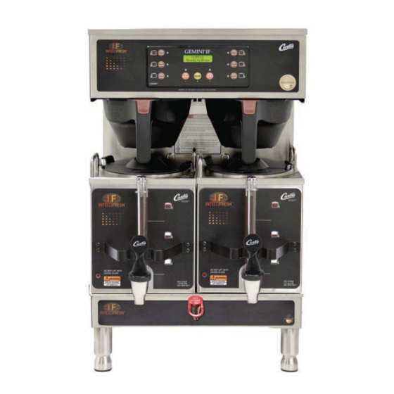
- Page 1 USER GUIDE G3 Gemini IntelliFresh Series ® ® Coffee Brewing System READ AND SAVE THESE INSTRUCTIONS NOTICE TO INSTALLER: Please leave this booklet with the machine.
-
Page 2: Table Of Contents
.........................ES6 ..........................ES29 ..............................................................................................................................EC4 ..............................Contact Information Wilbur Curtis Co., Inc. 6913 Acco Street | Montebello, CA 90640 US Phone: 323-837-2300 | Toll Free: 800-421-6150 Email: csrassistance@wilburcurtis.com | Web: www.wilburcurtis.com . - 4:00 . PT Email: techsupport@wilburcurtis.com... -
Page 3: Fs2
KEY FEATURES/SPECIFICATIONS/SYSTEM REQUIREMENTS Key Features • ® • Gold Cup • • • • • 12.0 gal/hr Single, 1.5 Gallon with IntelliFresh 1 PH 220 V 18.5 A 2 X 2000 W 3W + G 4050 W 50/60 Hz [45.4 l/hr] Single, 1.5 Gallon with IntelliFresh, 12.0 gal/hr 1 PH... -
Page 4: Is2
INSTRUCTIONS could result in personal injury or void the warranty. • This appliance is designed for commercial use. Any service other than cleaning and preventive maintenance should be performed by an authorized Wilbur Curtis service technician. • serviceable parts inside. - Page 5 IMPORTANT SAFEGUARDS CE Requirements • This appliance must be installed in locations where it can be overseen by trained personnel. • • This appliance is not suitable for outdoor use. • • • This appliance must not be cleaned by water jet. •...
-
Page 6: Ii2
INSTALLATION INSTRUCTIONS WARNING: WARNING: Improper electrical connection may result in an electric shock hazard or damage the unit. This appliance must be properly grounded. NOTICE: DO NOT connect this appliance to a hot water supply. The water inlet valve is not rated for hot water. -
Page 7: Ii1
INSTALLATION INSTRUCTIONS Installation Leveling WARNING: Use the leveling legs to level the brewer only. Do not use them to adjust brewer height. Do not extend them higher than necessary. Position the brewer on the counter top. Level it left to right and front to back by turning the bottom of the legs. - Page 8 INSTALLATION INSTRUCTIONS Connect the Brewer Wiring (cont.) Brewers With A Cord Set Attached - 12 Connect the power cord to the appropriate type of electrical outlet. WARNING: Connect the power cord to the appropriate type and size electrical outlet. If the electrical outlet is not compatible with the power cord, have it upgraded by a licensed electrician.
- Page 9 INSTALLATION INSTRUCTIONS 19 If the UCM is not already lit, push the ON/OFF button to the correct volume, the heating elements will turn on automatically. Depending on the incoming water water tank typically requires 20 to 30 minutes to the water has heated, “Ready to Brew” should be on the display.
-
Page 10: Oi1
OPERATING INSTRUCTIONS Brewing Instructions WARNING - TO AVOID SCALDING, AVOID SPLASHING. Keep body parts clear of the brewer during brewing. Do not remove the brew basket while “Brewing” appears on the display. NOTICE - Only use IntelliFresh satellites on IntelliFresh brewers. ®... - Page 11 INTELLIFRESH FEATURES ® IntelliFresh Function and Features The IntelliFresh Quality Timer system will alert you to when the coffee has exceeded the desired freshness time. The Quality Timer is activated by a connector on the satellite connecting to a corresponding connector on the brewer.
- Page 12 CLEANING INSTRUCTIONS WARNING: HOT SURFACES - To avoid injury, allow the brewer and dispenser(s) to cool before cleaning. NOTICE - Do not use cleaning liquids, compounds or powders containing chlorine (bleach) or corrosives. USE OF THESE PRODUCTS WILL VOID THE WARRANTY. Cleaning The Brewer - Daily WARNING: DO NOT immerse the brewer in water or any other liquid.
- Page 13 Mild solution of dish-washing detergent and warm water ™ • TABZ Z95 Coffee Equipment Cleaner Tablets (Curtis PN WC-79000) • One-Pro Beverage Equipment Cleaner WARNING: DO NOT immerse the satellite in water or any other liquid. Do not place the satellite in a dishwasher.
- Page 14 CLEANING INSTRUCTIONS Cleaning the Faucet Parts and Site Gauge 10 Wash - Wash the lid and all faucet and gauge glass parts with the detergent solution. Clean the inside of the gauge glass with a gauge brush soaked with detergent solution. 11 Rinse - Thoroughly rinse all parts with clean, WASH warm water.
- Page 15 PROGRAMMING GUIDE Wilbur Curtis To enter programming mode: With unit OFF, press and hold Wilbur Curtis bottom right BREW button (4). Ready to Brew* Then press and release ON/OFF button (2). Continue to hold down BREW button until Enter Code appears.
- Page 16 PROGRAMMING GUIDE Programming Options See the previous page for instructions on accessing each individual menu. Some menus save and exit automatically when a parameter is updated. Other menus exit to the previous menu when a parameter is saved. To exit, press until EXIT appears on the display, then press Global Recipes Menu Select from the following coffee recipes: Gourmet STD (standard), Light Roast, Dark Roast, High Yield, Filter...
- Page 17 PROGRAMMING GUIDE Non-Brew Programming Menu Non-Brew Prog Banner Name Warmers Default Brew Count Total QT Alarm On/Off <-- Select --> <-- Select --> <-- Select --> <-- Select --> <-- Select --> Press Select Select Select Select Temperature Cold Brew Lock Warmers Auto-Off Display Brew Time Satellite Color...
- Page 18 Banner Name - changes the company name that appears on the display. The factory default is Curtis. No name appears when all blanks are entered. Once accessed, press to choose the letter to change.
- Page 19 PROGRAMMING GUIDE Non-Brew Programming Menu (cont.) Display Brew Time - turns the display of the brew time during brewing On or Off. The factory default setting is On. Once accessed, press to choose the desired setting, then press to exit. Display Messages - turns display of the message “Rinse Server Before Brewing”...
- Page 20 PROGRAMMING GUIDE Brew Button Programming Menu (cont.) Brew by Time - adjusts the amount of coffee brewed by time rather than by volume. The factory default to change the number value. Press repeatedly to change the number value. Press repeatedly to exit.
- Page 21 PROGRAMMING GUIDE Model Select Menu - changes the model number and number of batches (to match the label on the universal control module, the factory default is Gemini-Twin, One batch). Once accessed, press until the model number matching the model number label on the brewer appears, then press Press until the number of to exit.
- Page 22 ROUGH-IN DRAWINGS GEMTIF - Twin Coffee Brewer 0.90 in [2.3 cm] 22.39 in 30.83 in [56.9 cm] 11.99 in [78.3 cm] [30.5 cm] 12.78 in [32.5 cm] 7.82 in 18.11 in [19.9 cm] [46.0 cm] 5.52 in 4.00 in [14.0 cm] [10.2 cm] GEMSIF - Single Coffee Brewer 0.87 in...
- Page 23 ROUGH-IN DRAWINGS RD75 GEM3IF - Satellite Server 13.48 in [34.2 cm] 8.94 in [22.7 cm] 11.48 in 10.28 in 11.72 in [29.2 cm] [26.1 cm] [29.8 cm] 9.98 in [25.3 cm] 8.94 in 0.27 in [22.7 cm] [0.7 cm] GEM3IF, ROUGH-IN DRAWING 062317NC...
- Page 24 ILLUSTRATED PARTS LIST GEMTIF - Main Chassis - Exploded View Water tank assembly, see section IP26 See satellite user guide for satellite replacement parts. GEMSIF/GEMTIF - GENERIC, ILLUSTRATED PARTS/RECOMMENDED PARTS 090519F...
-
Page 25: Ip2
WC-596K 3 KIT, NOISE FILTER EMI 250V/30A 1PH LABEL, UCM OVERLAY PANEL 2-BATCH GEMTIF WC-61954 1,3 PLATE, BREW CONE STOP SSTL GEMTIF WC-39756 CURTIS WC-61954-BLK 2 PLATE, BREW CONE STOP GEMTIF BLK LABEL, UCM OVERLAY PANEL 1-BATCH GEMTIF WC-39755 WC-1412 CORD GRIP, 3/4”... - Page 26 ILLUSTRATED PARTS/RECOMMENDED PARTS GEMSIF - Main Chassis - Exploded View Water tanks assemblies: Single voltage units, see section IP31 Dual voltage units, see section IP32 See satellite user guide for satellite replacement parts. GEMSIF/GEMTIF - GENERIC, ILLUSTRATED PARTS/RECOMMENDED PARTS 090519F...
- Page 27 WC-13379 4 GEMSS/GEMTS GEMSS30 (INCLUDES TERMINAL BLOCK) LABEL, UCM PANEL 3-BATCH GEMSIF WC-39801 WC-1412 CORD GRIP, 3/4” FOR METAL CORD TO .81”OD INTELLIFRESH CURTIS WC-571K-R KIT, IF CONNECTOR- RIGHT LABEL, UCM PANEL 2-BATCH GEMSIF WC-39802 INTELLIFRESH CURTIS WC-5350 TUBE, 1/2 ID x 1/8W SILICONE GEN USE...
-
Page 28: Ip26
ILLUSTRATED PARTS/RECOMMENDED PARTS IP26 WC-62033 - Tank Assembly WC-62033 - Tank Assembly - Parts List ITEM # PART # DESCRIPTION ITEM # PART # DESCRIPTION WC-54287 TANK, ASSY TPS1T/GEMTS WC-1438-101 SENSOR, TEMPERATURE TANK WC-62033 TANK, COMPLETE GEMTS W/ULTEM FITTINGS WC-4382 GUARD, SHOCK HTNG ELMNT DOUBLE WC-37008 KIT, TANK LID ROUND (INCLUDES GASKET) -
Page 29: Ip31
ILLUSTRATED PARTS LIST IP31 WC-62035 - Tank Assembly WC-62035 - Tank Assembly - Parts List ITEM # PART # DESCRIPTION ITEM # PART # DESCRIPTION WC-62035 TANK, COMPLETE GEMSS W/ULTEM FITTINGS THERMOSTAT, HI LIMIT HEATER CONTROL DPST WC-522 277V 40A WC-5853-102 COVER, TOP HEATING TANK GEN USE WC-43055... -
Page 30: Ip32
ILLUSTRATED PARTS LIST IP32 WC-62034 - Tank Assembly WC-62034 - Tank Assembly - Parts List ITEM # PART # DESCRIPTION TANK, COMPLETE GEMSS DV W/ ULTEM ITEM # PART # DESCRIPTION WC-62034 FITINGS THERMOSTAT, HI LIMIT HEATER CONTROL WC-522 WC-5853-102 COVER, TOP HEATING TANK GEN USE DPST 277V 40A WC-43055... -
Page 31: Es2
ELECTRICAL SCHEMATICS GEMSIF10A1000, GEMSIF10B1000 GEMSIF10A1000/GEMSIF10B1000, ELECTRICAL SCHEMATIC 022717A... -
Page 32: Es3
ELECTRICAL SCHEMATICS GEMSIF63A1000 GEMSIF63A1000, ELECTRICAL SCHEMATIC 022717NC... -
Page 33: Es4
ELECTRICAL SCHEMATICS GEMSIF30A1000, GEMXSIFT30A1000 UCM Pin Assignments 20 Pin Connector GRINDER INTERLOCK COMMON-SOLID STATE RELAY & GRINDER SOLID STATE RELAY +5 Vdc BREW CONE LOCK NOT USED INLET VALVE BYPASS VALVE NOT USED IF WARMER NOT USED NOT USED NOT USED TANK TEMPERATURE SENSOR TANK TEMPERATURE SENSOR UCM GROUND... - Page 34 ELECTRICAL SCHEMATICS GEMTIF10A1000, GEMTIF10B1000...
-
Page 35: Es6
ELECTRICAL SCHEMATICS GEMTIF30A1000, GEMXTIFT30A1000 UCM Pin Assignments 20 Pin Connector GRINDER INTERLOCK COMMON-SOLID STATE RELAY & GRINDER SOLID STATE RELAY +5 Vdc BREW CONE LOCK RIGHT BREW CONE LOCK LEFT INLET VALVE BYPASS VALVE RIGHT IF WARMER LEFT IF WARMER RIGHT BYPASS VALVE LEFT NOT USED NOT USED... -
Page 36: Es29
ELECTRICAL SCHEMATICS ES29 GEM3IF Pin Assignments 120V HOT 120V NEUTRAL ELECTRICAL RATING TABLE TANK TEMPERATURE SENSOR # of TANK TEMPERATURE SENSOR Voltage Amps Wa s Hertz Model Conductor Phase HEATER/WARMER OUT Wires HEATER/WARMER OUT 0.55 50/60 LED (+) GEM3IFx 0.58 50/60 LED (-) 0.60... - Page 37 ELECTRICAL SCHEMATICS ES30 GEM3IF-30...
- Page 38 TROUBLESHOOTING GUIDE WARNING: Electric Shock Hazard - Scald and Burn Hazard - IMPORTANT: always Valve Test Procedure ELECTRICAL SCHEMATIC Troubleshooting Guidelines ERROR CODES • • • Use this troubleshooting guide along with the appropriate ELECTRICAL SCHEMATIC. • Valve Test Procedure in either direction Water Not Hot Enough replace the temperature sensor...
- Page 39 TROUBLESHOOTING GUIDE During Brewing ELECTRICAL SCHEMATIC No Power - Display Not Lit Water Tank Does Not Fill Brewer Does Not Start When Brew Button is Pressed Brewing Brewing Sensor Error Message...
- Page 40 TROUBLESHOOTING GUIDE Water Tank Does Not Fill IMPORTANT: Coffee/Tea Too Strong Dispenser Not Filled To Normal Level During Brewing Dispenser Not Filled To Normal Level During Brewing SPECIFICATIONS sure that the spray head is correctly aligned and that the tubing is routed properly to allow for maximum water ELECTRICAL SCHEMATIC...
- Page 41 TROUBLESHOOTING GUIDE All Of The Time ELECTRICAL SCHEMATIC No Water/Tea Flows From Brewer During Brewing Water Tank Does Not Fill ELECTRICAL SCHEMATIC Low Water Flow Warning Water Level Error Message Water Level Error Message ERROR CODES SPECIFICATIONS...
- Page 42 TROUBLESHOOTING GUIDE Water Does Not Heat At All Check to see if the water level in the tank is in contact with the water level probe. If not, see Tank Does Not Fill. • The water will not heat unless it is in contact with the probe. If the water heats, but is not hot enough, see Water Not Hot Enough.
- Page 43 TROUBLESHOOTING GUIDE TG13 Satellite Does Not Heat NOTE reheat cold coffee. (replace the controller). Check to make sure that the warmer is not turned off. See the PROGRAMMING GUIDE section. Check to see if the IntelliFresh LED on the front of the satellite comes on at the beginning of the brew cycle. If neither the LED nor the warmer come on, then it can be assumed that there is no power to the satellite.
-
Page 44: Ec4
ERROR CODES System Fault Messages An error message will appear on the screen in the event of a malfunction under the following conditions: ERROR MESSAGE WARNING DESCRIPTION CAUSE Water Level Error G3 BREWER, ERROR CODES 042017A... - Page 45 Return Merchandise Authorization (RMA): All returned equipment must be properly re-packaged in the original carton and received by Curtis within 45 days following the issuance of a RMA. NO UNITS OR PARTS WILL BE ACCEPTED WITHOUT A RETURN MERCHANDISE AUTHORIZATION (RMA).