
Related Manuals for Omron R88D-1SN10F-ECT


Summary of Contents for Omron R88D-1SN10F-ECT
- Page 1 AC Servomotors/Servo Drives 1S-series with Built-in EtherCAT Communications ® User’s Manual R88M-1L /-1M (AC Servomotors) R88D-1SN -ECT (AC Servo Drives) I586-E1-04...
- Page 2 No patent liability is assumed with respect to the use of the information contained herein. Moreover, because OMRON is constantly striving to improve its high-quality products, the information contained in this manual is subject to change without notice. Every precaution has been taken in the preparation of this manual. Neverthe- less, OMRON assumes no responsibility for errors or omissions.
-
Page 3: Introduction
Introduction Introduction Thank you for purchasing a 1S-series Servo Drive. This User’s Manual describes the installation and wiring methods of the 1S-series Servo Drives and parameter setting method which is required for the operation, as well as troubleshooting and inspection methods. Intended Audience This User’s Manual is intended for the following personnel, who must also have electrical knowledge (certified electricians or individuals who have equivalent knowledge). -
Page 4: Manual Structure
Manual Structure Manual Structure This section explains the page structure and symbol icons. Page Structure The following page structure is used in this manual. Level 1 7 Applied Functions heading Soft Start Function Level 2 heading This function sets the acceleration and deceleration against the velocity command input inside the Servo Drive and uses these values for speed control. -
Page 5: Level
Manual Structure 7 Applied Functions Special information Precautions for Correct Use Do not set the Acceleration Time and the Deceleration Time when the position loop structure Icons indicate precautions, with a host controller is used. additional information, or reference information. 7-9-3 Velocity Command Filter (First-order Lag) The velocity command filter (first-order lag) is an IIR filter used for speed commands. -
Page 6: Manual Configuration
Manual Configuration Manual Configuration This User’s Manual consists of the following sections. Read the necessary section or sections by reference to the following table. Section Outline Features and Sys- This section explains the features of the Servo Drive and name of each part. Section 1 tem Configuration This section explains the models of Servo Drives, Servomotors, Decelera-... -
Page 7: Sections In This Manual
Sections in this Manual Sections in this Manual Features and System Operation Configuration Models and External Adjustment Functions Dimensions Specifications Troubleshooting Configuration and Maintenance and Wiring Inspection EtherCAT Appendices Communications Basic Control Index Functions Applied Functions Safety Function Details on Servo Parameters AC Servomotors/Servo Drives 1S-series with Built-in EtherCAT®... -
Page 8: Table Of Contents
CONTENTS CONTENTS Introduction ......................1 Manual Structure ...................... 2 Manual Configuration ....................4 Sections in this Manual ................... 5 Terms and Conditions Agreement ................ 16 Safety Precautions ....................18 Items to Check After Unpacking ................29 Related Manuals ..................... 38 Terminology ...................... - Page 9 CONTENTS Section 2 Models and External Dimensions Servo System Configuration ....................2-2 How to Read Model Numbers..................... 2-4 2-2-1 Servo Drive..........................2-4 2-2-2 Servomotor..........................2-5 2-2-3 Decelerator (Backlash: 3 Arcminutes Max.) ................2-6 2-2-4 Decelerator (Backlash: 15 Arcminutes Max.) ................2-7 Model Tables ........................
- Page 10 CONTENTS Specifications of External Regeneration Resistors and External Regeneration Resistance Units........................ 3-93 3-5-1 General Specifications ......................3-93 3-5-2 Characteristics ........................3-94 3-5-3 External Regeneration Resistance Unit Specifications ............3-96 Reactor Specifications ...................... 3-97 3-6-1 General Specifications ......................3-97 3-6-2 Characteristics ........................3-97 3-6-3 Terminal Block Specifications ....................
- Page 11 Cyclic Synchronous Velocity Mode ................. 6-12 Cyclic Synchronous Torque Mode................... 6-14 Profile Position Mode......................6-16 Profile Velocity Mode ......................6-21 Homing Mode........................6-24 Connecting with OMRON Controllers................6-25 Section 7 Applied Functions General-purpose Input Signals ..................7-3 7-1-1 Objects Requiring Settings ....................... 7-4 7-1-2 Default Setting..........................
- Page 12 CONTENTS Soft Start..........................7-32 7-9-1 Objects Requiring Settings ..................... 7-32 7-9-2 Soft Start Acceleration/Deceleration Time ................7-32 7-9-3 Velocity Command First-order Lag Filter ................7-33 7-10 Gain Switching Function ....................7-34 7-10-1 Objects Requiring Settings ..................... 7-34 7-10-2 Mode Selection ........................7-36 7-10-3 Gain Switching in Position Control..................
- Page 13 CONTENTS Control Loop Objects ......................9-32 9-4-1 3210 hex: Internal Position Command ................... 9-32 9-4-2 3211 hex: Position Detection ....................9-33 9-4-3 3212 hex: Gain Switching in Position Control ................ 9-33 9-4-4 3213 hex: 1st Position Control Gain..................9-34 9-4-5 3214 hex: 2nd Position Control Gain..................
- Page 14 CONTENTS 9-13 Encoder-related Objects ....................9-102 9-14 I/O-related Objects......................9-105 9-14-1 4600 hex: I/O Monitor ......................9-105 9-14-2 4601 hex: Function Input ...................... 9-106 9-14-3 4602 hex: Function Output ....................9-108 9-14-4 4604 hex: Control Input Change Count ................9-109 9-14-5 4605 hex: Control Output Change Count ................
- Page 15 CONTENTS 10-3 Test Run ..........................10-8 10-3-1 Preparations for Test Run....................... 10-8 10-3-2 Test Run via USB Communications from the Sysmac Studio ..........10-9 Section 11 Adjustment Functions 11-1 Outline of Adjustment Functions..................11-3 11-1-1 Adjustment Methods........................11-3 11-1-2 Adjustment Procedure......................11-4 11-2 Easy Tuning ........................
- Page 16 CONTENTS 12-4 Information........................12-13 12-4-1 Related Objects ........................12-13 12-4-2 Information List ........................12-13 12-5 Troubleshooting ......................12-14 12-5-1 Troubleshooting Using Error Displays .................. 12-14 12-5-2 Troubleshooting Using AL Status Codes ................12-34 12-5-3 Troubleshooting Using the Operation State ................12-38 Section 13 Maintenance and Inspection 13-1...
- Page 17 CONTENTS AC Servomotors/Servo Drives 1S-series with Built-in EtherCAT® Communications User’s Manual (I586)
-
Page 18: Terms And Conditions Agreement
Omron’s exclusive warranty is that the Products will be free from defects in materials and workman- ship for a period of twelve months from the date of sale by Omron (or such other period expressed in writing by Omron). Omron disclaims all other warranties, express or implied. - Page 19 Disclaimers Performance Data Data presented in Omron Company websites, catalogs and other materials is provided as a guide for the user in determining suitability and does not constitute a warranty. It may represent the result of Omron’s test conditions, and the user must correlate it to actual application requirements. Actual perfor- mance is subject to the Omron’s Warranty and Limitations of Liability.
-
Page 20: Safety Precautions
Safety Precautions Safety Precautions • To ensure that the 1S-series Servomotor/Servo Drive as well as peripheral equipment are used safely and correctly, be sure to read this Safety Precautions section and the main text before using the product. Learn all items you should know before use, regarding the equipment as well as the required safety information and precautions. - Page 21 When you use this product, be sure to install the covers and shields as specified and use the product according to this manual. • If the product has been stored for an extended period of time, contact your OMRON sales represen- tative.
- Page 22 Safety Precautions Installing Safety Products Qualified engineers must develop your safety-related system and install safety products in devices and equipment. Prior to machine commissioning, verify through testing that the safety products work as expected. The following are examples of related international standards. •...
- Page 23 Before carrying out wiring or inspection, turn OFF the main circuit power and wait for at least the following specific time. Not doing so may cause electric shock or burning. 10 minutes: R88D-1SN06F-ECT, R88D-1SN10F-ECT, R88D-1SN15F-ECT, R88D-1SN20F-ECT, R88D-1SN30F-ECT 15 minutes: R88D-1SN01L-ECT, R88D-1SN02L-ECT, R88D-1SN01H-ECT,...
- Page 24 Safety Precautions Usage WARNING Do not enter the operating area during operation. Doing so may cause injury. Do not touch the Servo Drive radiator, Regeneration Resistor, or Servomotor while the power is supplied or for a while after the power is turned OFF because they get hot. Doing so may cause fire or a burn injury.
- Page 25 Safety Precautions Transporting and Unpacking Caution When transporting the Servo Drive, do not hold it by the cables or motor shaft. Injury or failure may result. Do not step on the Servo Drive or place heavy articles on it. Injury may result. Do not overload the product.
- Page 26 Safety Precautions Precautions for Safe Use General Precaution • Do not store or install the Servo Drive in the following locations. Doing so may result in electric shock, fire, equipment damage, or malfunction. Locations subject to direct sunlight Locations subject to temperatures outside the range specified in the specifications Locations subject to humidity outside the range specified in the specifications Locations subject to condensation as the result of severe changes in temperature Locations subject to corrosive or flammable gases...
- Page 27 Safety Precautions Installation • Be sure to observe the mounting direction. Failure may result. • Provide the specified clearance between the Servo Drive and the inner surface of the control panel or other equipment. Fire or failure may result. • Install the Servomotor, Servo Drive, and Regeneration Resistor on non-flammable materials such as metals.
- Page 28 Safety Precautions Adjustment • Install an immediate stop device externally to the machine so that the operation can be stopped and the power supply is cut off immediately. Injury may result. • Do not adjust or set parameters to extreme values, because it will make the operation unstable. Injury may result.
- Page 29 Safety Precautions • Periodically run the Servomotor approximately one rotation when the oscillation operation continues at a small angle of 45° or smaller. Servomotor failure may result. • Immediately stop the operation and cut off the power supply when unusual smell, noise, smoking, abnormal heat generation, or vibration occurs.
- Page 30 Safety Precautions Disposal Dispose of the Servo Drive as industrial waste. AC Servomotors/Servo Drives 1S-series with Built-in EtherCAT® Communications User’s Manual (I586)
-
Page 31: Items To Check After Unpacking
Notation: Lot No. DDMYY xxxx DDMYY: Lot number, : For use by OMRON, xxxx: Serial number “M” gives the month (1 to 9: January to September, X: October, Y: November, Z: December) Accessories of Servo Drive This product comes with the following accessories. - Page 32 Connectors, mounting screws, mounting brackets, and other accessories other than those in the table below are not supplied. They must be prepared by the customer. If any item is missing or a problem is found such as Servo Drive damage, contact the OMRON dealer or sales office where you purchased your product.
- Page 33 Items to Check After Unpacking Servomotor The model, rating and serial number of the 1S-series Servomotor are given on the product nameplate. Motor model From the left, R88M-1M2K020T-BOS2 Number of phases (Example: 3) Rated voltage (Example: 200 VAC) 200VAC 13.3 A 2.0 kW Rated current 250 Hz 10kg...
- Page 34 Χ Χ - Χ Χ Χ Χ Χ Χ Χ - Χ Χ Χ Upper row: Model on nameplate Lower row: Serial No. (the OMRON logo at the end) The model on nameplate HPG-14A-05-J2AXT corresponds to the decelerator model HPG14A05200B.
- Page 35 Items to Check After Unpacking Decelerator (backlash: 3 arcminutes max.) for 3,000-r/min Servomotors Specifications Without key With key and tap Servo- Reduc- motor tion Decelerator model Model on nameplate Decelerator model Model on nameplate rated ratio output R88G- HPG-11B-05-J2ADG R88G- HPG-11B-05-J6ADG HPG11B05100B HPG11B05100BJ...
- Page 36 Items to Check After Unpacking Specifications Without key With key and tap Servo- Reduc- motor tion Decelerator model Model on nameplate Decelerator model Model on nameplate rated ratio output R88G- HPG-32A-05-J2NFG R88G- HPG-32A-05-J6NFG HPG32A052K0B HPG32A052K0BJ R88G- HPG-32A-11-J2NFH R88G- HPG-32A-11-J6NFH 1/11 HPG32A112K0B HPG32A112K0BJ R88G-...
- Page 37 Items to Check After Unpacking Decelerator (backlash: 3 arcminutes max.) for 2,000-r/min Servomotors Specifications Without key With key and tap Servo- Reduc- motor tion Decelerator model Model on nameplate Decelerator model Model on nameplate rated ratio output R88G- HPG-32A-05-J2NFG R88G- HPG-32A-05-J6NFG HPG32A052K0B HPG32A052K0BJ...
- Page 38 Items to Check After Unpacking Specifications Without key With key and tap Servo- Reduc- motor tion Decelerator model Model on nameplate Decelerator model Model on nameplate rated ratio output R88G- HPG-32A-05-J2PAO R88G- HPG-32A-05-J6PAO HPG32A054K0B HPG32A054K0BJ R88G- HPG-50A-11-J2BADC R88G- HPG-50A-11-J6BADC 1/11 HPG50A115K0B HPG50A115K0BJ 3 kW...
- Page 39 RATIO POWER (Example: 100 W) (Example: 1/5) XXXXXXXXX Serial number LOT NO. Ship date XXXX.XX DATE OMRON Corporation MADE IN CHINA (Rubber cap) Nameplate display location (Rubber cap side) AC Servomotors/Servo Drives 1S-series with Built-in EtherCAT® Communications User’s Manual (I586)
-
Page 40: Related Manuals
Related Manuals Related Manuals The following are the manuals related to this manual. Use these manuals for reference. Manual name Cat. No. Model numbers Application Description NX-series CPU W535 NX701- Learning the basic speci- An introduction to the entire Unit Hardware fications of the NX-series NX-series system is pro- User’s Manual... - Page 41 Related Manuals Manual name Cat. No. Model numbers Application Description NJ/NX-series CPU W501 NX701- Learning how to program The following information is Unit Software and set up an provided on a Controller built NX1P2- User’s Manual NJ/NX-series CPU Unit. with an NJ/NX-series CPU NJ501- Mainly software informa- Unit.
-
Page 42: Terminology
Terminology Terminology Abbrevi- Term Description ation CAN application protocol over EtherCAT A CAN application protocol service implemented on EtherCAT. CAN in Automation CiA is the international users’ and manufacturers’ group that develops and supports higher-layer proto- cols. Device Profile Collection of device dependent information and func- tionality providing consistency between similar devices of the same device type. - Page 43 Terminology Abbrevi- Term Description ation safety reaction time The time required for the system to enter a safe state in a worst-case scenario after the occurrence of a safety-related input (press of an emergency stop pushbutton switch, interruption of a light curtain, opening of a safety door, etc.) or device failure.
-
Page 44: Revision History
Revision History Revision History The manual revision code is a number appended to the end of the catalog number found in the front and back cover. Example I586-E1-04 Cat. No. Revision code Revision Date Revised content code June 2016 Original production August 2016 •... -
Page 45: Features And System Configuration
Features and System Configura- tion This section explains the features of the Servo Drive and name of each part. 1-1 Outline ............1-2 1-1-1 Features of 1S-series Servo Drives . -
Page 46: Outline
NJ/NX-series Machine Automation Controller and the Sysmac Studio Automation Software. Sysmac Device is a generic term for OMRON control devices such as an EtherCAT Slave, designed with unified communications specifications and user interface specifications. -
Page 47: Ethercat
1 Features and System Configuration Safe Torque OFF (STO) Function to Ensure Safety You can cut off the motor current to stop the motor based on a signal from an emergency stop button or other safety equipment. This can be used for an emergency stop circuit that is compliant with safety standards without using an external contactor. -
Page 48: Object Dictionary
Definitions of objects that can be used by all serv- ers for designated communications. 2000 to 2FFF Manufacturer Specific Area 1 Objects with common definitions for all OMRON products. 3000 to 5FFF Manufacturer Specific Area 2 Objects with common definitions for all 1S-series Servo Drives (servo parameters). -
Page 49: System Configuration
1 Features and System Configuration System Configuration The system configuration for a 1S-series Servo Drive with Built-in EtherCAT Communications is shown below. Controller (EtherCAT type) Controller (EtherCAT type) Eth er EtherCAT 24 VDC 7 mA Machine Automation Controller NJ/NX-series 1S-series Servo Drive R88D-1SN -ECT Position Control Unit... -
Page 50: Names And Functions
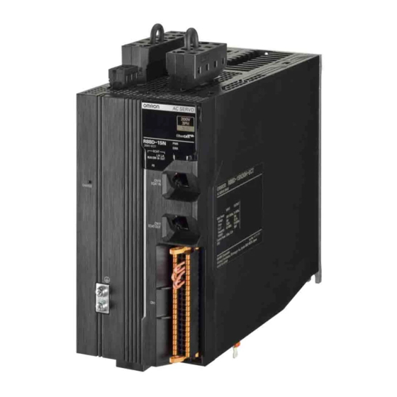
1 Features and System Configuration Names and Functions This section describes the names and functions of Servo Drive parts. 1-3-1 Servo Drive Part Names The Servo Drive part names are given below. R88D-1SN01L-ECT/-1SN02L-ECT/-1SN04L-ECT/-1SN01H-ECT/ -1SN02H-ECT/-1SN04H-ECT/-1SN08H-ECT/-1SN10H-ECT Main circuit connector (CNA) terminal 7-segment LED display Status indicators C N 7 ID switches... - Page 51 1 Features and System Configuration Encoder connector (CN2) Brake interlock connector (CN12) Motor connector (CNC) terminal 1 - 7 AC Servomotors/Servo Drives 1S-series with Built-in EtherCAT® Communications User’s Manual (I586)
- Page 52 1 Features and System Configuration R88D-1SN15H-ECT/-1SN20H-ECT/-1SN30H-ECT/-1SN06F-ECT/ -1SN10F-ECT/-1SN15F-ECT/-1SN20F-ECT/-1SN30F-ECT Main circuit connector A (CNA) Main circuit Control power connector B (CNB) supply connector (CND) 7-segment Status indicators LED display ID switches USB connector Status indicators EtherCAT communications C H AR G E C N 10 EC AT IN connector...
- Page 53 1 Features and System Configuration Encoder connector (CN2) Brake interlock connector (CN12) Motor connector terminal (CNC) 1 - 9 AC Servomotors/Servo Drives 1S-series with Built-in EtherCAT® Communications User’s Manual (I586)
-
Page 54: Servo Drive Functions
1 Features and System Configuration 1-3-2 Servo Drive Functions The functions of each part of the Servo Drive are described below. Status Indicators The following seven indicators are mounted. Name Color Description Green Displays the status of control power supply. Gives the Servo Drive error status. - Page 55 1 Features and System Configuration EtherCAT Communications Connectors (ECAT IN CN10, ECAT OUT CN11) These connectors are for EtherCAT communications. USB Connector (CN7) USB-Micro B Communications connector for the computer. This connector enables USB 2.0 Full Speed (12 Mbps) communications. Brake Interlock Connector (CN12) Used for brake interlock signals.
-
Page 56: Servomotor Part Names
1 Features and System Configuration Terminal The number of terminals of the Servo Drives and their connection targets are as follows. Number of Servo Drive model Connection to terminals R88D-1SN01L-ECT/ 1 on top PE wire of the main circuit power supply cable. -1SN02L-ECT/-1SN04L-ECT/ 2 on front FG wire inside the control panel, and FG wire for... -
Page 57: Servomotor Functions
1 Features and System Configuration Flange Size of 100 x 100 or more Encoder connector Power/brake connector Flange Shaft Mating part 200 VAC 1.5 kW Servomotors (with Brake) 1-3-4 Servomotor Functions The functions of each part of the Servomotor are described below. Shaft The load is mounted on this shaft. -
Page 58: System Block Diagram
1 Features and System Configuration System Block Diagram The block diagram of a 1S-series Servo Drive with Built-in EtherCAT Communications is shown below. R88D-1SN01L-ECT/-1SN02L-ECT/-1SN01H-ECT/-1SN02H-ECT/ -1SN04H-ECT DC/DC 24 V Power supply P/B1 Relay drive Regeneration Fuse control Gate drive Current detection error detection Voltage detection Overcurrent detection... - Page 59 1 Features and System Configuration R88D-1SN04L-ECT/-1SN08H-ECT/-1SN10H-ECT DC/DC 24 V Power supply P/B1 Relay drive Regeneration Fuse control Gate drive Current detection error detection Overcurrent Voltage detection HS temperature detection monitoring Input voltage monitoring (IPM error) MPU, FPGA Control circuit Display area rotary switch ECAT IN ECAT OUT...
- Page 60 1 Features and System Configuration R88D-1SN15H-ECT/-1SN20H-ECT/-1SN30H-ECT DC/DC +24 V Power supply Relay drive Regeneration control Gate drive Current detection Fuse Overcurrent Voltage detection HS temperature detection Input voltage monitoring monitoring (IPM error) MPU, FPGA Control circuit Display area rotary switch ECAT IN ECAT OUT CN12...
- Page 61 1 Features and System Configuration R88D-1SN06F-ECT/-1SN10F-ECT/-1SN15F-ECT/-1SN20F-ECT/ -1SN30F-ECT DC/DC +24 V power supply Relay drive Regeneration control Gate drive Current detection Fuse Overcurrent Voltage detection HS temperature detection Input voltage monitoring monitoring (IPM error) MPU, FPGA Control circuit Display area rotary switch ECAT IN ECAT OUT CN12...
-
Page 62: Applicable Standards
CLASS gG 16A R88D-1SN15H-ECT CLASS gG 40A R88D-1SN20H-ECT CLASS gG 40A R88D-1SN30H-ECT CLASS gG 40A R88D-1SN06F-ECT CLASS gG 20A R88D-1SN10F-ECT CLASS gG 20A R88D-1SN15F-ECT CLASS gG 20A R88D-1SN20F-ECT CLASS gG 20A R88D-1SN30F-ECT CLASS gG 20A 1 - 18 AC Servomotors/Servo Drives 1S-series with Built-in EtherCAT® Communications User’s Manual (I586) -
Page 63: Ul And Cul Standards
UL CLASS RK5 40 A R88D-1SN20H-ECT UL CLASS RK5 40 A R88D-1SN30H-ECT UL CLASS RK5 40 A R88D-1SN06F-ECT UL CLASS RK5 20 A R88D-1SN10F-ECT UL CLASS RK5 20 A R88D-1SN15F-ECT UL CLASS RK5 20 A R88D-1SN20F-ECT UL CLASS RK5 20 A R88D-1SN30F-ECT... -
Page 64: Korean Radio Regulations (Kc)
1 Features and System Configuration 1-5-3 Korean Radio Regulations (KC) • Observe the following precaution if you use this product in Korea. Class A Device (Broadcasting Communications Device for Office Use) This device obtained EMC registration for office use (Class A), and it is intended to be used in places other than homes. -
Page 65: Unit Versions
1 Features and System Configuration Unit Versions The 1S-series Servo Drive uses unit versions. Unit versions are used to manage differences in supported functions due to product upgrades, etc. 1-6-1 Confirmation Method The unit version of 1S-series is displayed at the location shown below. Display location Display on the product Unit version... -
Page 66: Procedures To Start Operation
1 Features and System Configuration Procedures to Start Operation This section explains the procedures to operate a system that incorporates 1S-series Servo Drives. 1-7-1 Overall Procedure Use the following procedures to build a system that incorporates 1S-series Servo Drives. To use the Servo Drive safety function, you must build the standard control and safety control together. STEP 1 System Design STEP 1-1 Determining safety measures based on risk assessment STEP 1-2 Selecting standard devices, Servo Drive, Servomotor, and safety devices... - Page 67 1 Features and System Configuration STEP 8 Mounting and wiring STEP 8-1 Mounting STEP 8-2 Wiring STEP 10 Safety control operation check STEP 9 Standard control operation check STEP 9-1 Placing Sysmac Studio online STEP 10-1 Transferring configuration information and downloading project STEP 10-2 Checking operation with actual machine STEP 10-3 Conducting safety validation test STEP 9-2 Online Debugging...
-
Page 68: Procedure Details
1 Features and System Configuration 1-7-2 Procedure Details As described previously, the procedures for the standard control and safety control are performed in parallel. This section explains the procedure details for using the Servo Drive safety function. If you use an NJ/NX-series CPU Unit to perform the standard control, refer to NJ/NX-series CPU Unit Software User's Manual (Cat. - Page 69 1 Features and System Configuration STEP 3 Software and Hardware Design for Safety Control Procedure Description Reference STEP 3-1 Determine wiring used for the communication network, Safety Control Unit User's Determining wiring for power supply, and safety I/O devices. Manual communications, power supply, and connection with external I/O devices...
- Page 70 1 Features and System Configuration STEP 5 Software Design and Programming for Standard Control Procedure Description Reference • Register variables in the Sysmac Studio. NJ/NX-series CPU Unit User’s Manuals • Write the algorithms for the POUs (programs, func- STEP 5-4 Programming tion blocks, and functions) in the required languages.
- Page 71 1 Features and System Configuration STEP 7 Servo Drive Setting, Adjustment, and Operation Check Procedure Description Reference Connect the Servomotor and Servo Drive to the power supply and peripheral equipment. STEP 7-2 Section 4, 4-2 Wiring and connections Satisfy specified installation and wiring conditions, par- ticularly for models that conforms to the EU Directives.
- Page 72 1 Features and System Configuration STEP 10 Safety Control Operation Check Procedure Description Reference • Connect the computer (Sysmac Studio) to the • NJ/NX-series CPU Unit NJ/NX-series CPU Unit. User’s Manuals • Download the project data to the CPU Unit. •...
- Page 73 Models and External Dimensions This section explains the models of Servo Drives, Servomotors, Decelerators, and peripheral devices, and provides the external dimensions and mounting dimensions. 2-1 Servo System Configuration ........2-2 2-2 How to Read Model Numbers .
-
Page 74: Servo System Configuration
2 Models and External Dimensions Servo System Configuration This section shows the Servo system configuration that consists of Controllers, Servo Drives, Servomo- tors, Decelerators, and other devices. Support Software Controller ● Automation Software Sysmac Studio NJ/NX-series CPU Unit (with EtherCAT port) 24 VDC 7 mA Machine Automation Controller... - Page 75 2 Models and External Dimensions Servomotor Servo Drive Power signal Power cable ● Standard cable communications · Without brake wire R88A-CA1 · With brake wire R88A-CA1 ● Flexible cable · Without brake wire R88A-CA1 · With brake wire R88A-CA1 Eth er EtherCAT communications Brake cable for 750 W max.
-
Page 76: How To Read Model Numbers
2 Models and External Dimensions How to Read Model Numbers This section describes how to read and understand the model numbers of Servo Drives, Servomotors, and Decelerators. 2-2-1 Servo Drive The Servo Drive model number tells the Servo Drive type, applicable Servomotor, power supply volt- age, etc. -
Page 77: Servomotor
2 Models and External Dimensions 2-2-2 Servomotor The Servomotor model number tells the Servomotor type, rated output, rated rotation speed, voltage, etc. R88M-1M10030S-BOS2 1S-series Servomotor Servomotor type Low inertia Middle inertia Rated output 100 W 200 W 400 W 600 W 750 W 900 W 1 kW... -
Page 78: Decelerator (Backlash: 3 Arcminutes Max.)
2 Models and External Dimensions 2-2-3 Decelerator (Backlash: 3 Arcminutes Max.) The Decelerator model number tells the Decelerator series, flange size number, reduction ratio, appli- cable Servomotor, backlash, etc. R88G-HPG14A05100SBJ Decelerator for Servomotor Backlash: 3 Arcminutes max. Flange size number 40 x 40 60 x 60 90 x 90... -
Page 79: Decelerator (Backlash: 15 Arcminutes Max.)
2 Models and External Dimensions 2-2-4 Decelerator (Backlash: 15 Arcminutes Max.) The Decelerator model number tells the Decelerator series, flange size number, reduction ratio, appli- cable Servomotor, backlash, etc. R88G-VRXF09B100CJ Decelerator for Servomotor Backlash: 15 Arcminutes max. Reduction ratio : 1/5 : 1/9 : 1/15 : 1/25... -
Page 80: Model Tables
2 kW R88D-1SN20H-ECT P. 2-28 3 kW R88D-1SN30H-ECT 3-phase 400 VAC 600 W R88D-1SN06F-ECT 1 kW R88D-1SN10F-ECT 1.5 kW R88D-1SN15F-ECT 2 kW R88D-1SN20F-ECT 3 kW R88D-1SN30F-ECT 2 - 8 AC Servomotors/Servo Drives 1S-series with Built-in EtherCAT® Communications User’s Manual (I586) -
Page 81: Servomotor Model Tables
2 Models and External Dimensions 2-3-2 Servomotor Model Tables The following tables list the Servomotor models by the rated motor speed. 3,000-r/min Servomotors Model Refer- Specifications Without oil seal With oil seal ence Straight shaft With key and tap Straight shaft With key and tap 100 VAC 100 W... - Page 82 2 Models and External Dimensions Model Refer- Specifications Without oil seal With oil seal ence Straight shaft With key and tap Straight shaft With key and tap 100 VAC 100 W R88M- R88M- R88M- R88M- P. 2-30 1M10030S-B 1M10030S-BS2 1M10030S-BO 1M10030S-BOS2 200 W R88M-...
- Page 83 2 Models and External Dimensions 2,000-r/min Servomotors Model Refer- Specifications Without oil seal With oil seal ence Straight shaft With key and tap Straight shaft With key and tap 200 VAC 1 kW R88M- R88M- R88M- R88M- P. 2-43 1M1K020T 1M1K020T-S2 1M1K020T-O 1M1K020T-OS2...
- Page 84 2 Models and External Dimensions 1,000-r/min Servomotors Model Refer- Specifications Without oil seal With oil seal ence Straight shaft With key and tap Straight shaft With key and tap 200 VAC 900 W R88M- R88M- R88M- R88M- P. 2-53 1M90010T 1M90010T-S2 1M90010T-O 1M90010T-OS2...
-
Page 85: Servo Drive And Servomotor Combination Tables
R88D-1SN15H-ECT R88M-1L1K530T- 3-phase 200 VAC 1 kW R88D-1SN10H-ECT R88M-1L1K030T- 2 kW R88D-1SN20H-ECT R88M-1L2K030T- 3 kW R88D-1SN30H-ECT R88M-1L3K030T- 3-phase 400 VAC 750 W R88D-1SN10F-ECT R88M-1L75030C- 1 kW R88D-1SN10F-ECT R88M-1L1K030C- 1.5 kW R88D-1SN15F-ECT R88M-1L1K530C- 2 kW R88D-1SN20F-ECT R88M-1L2K030C- 3 kW R88D-1SN30F-ECT R88M-1L3K030C-... -
Page 86: Decelerator Model Tables
R88D-1SN10H-ECT 2 kW R88M-1M2K010T- R88D-1SN20H-ECT 3 kW R88M-1M3K010T- R88D-1SN30H-ECT 3-phase 400 VAC 900 W R88M-1M90010C- R88D-1SN10F-ECT 2 kW R88M-1M2K010C- R88D-1SN20F-ECT 3 kW R88M-1M3K010C- R88D-1SN30F-ECT 2-3-4 Decelerator Model Tables The following tables list the Decelerator models for 1S-series Servomotors. The standard shaft type is a straight shaft. A model with a key and tap is indicated with “J” at of the Decelerator model number in the following table. - Page 87 2 Models and External Dimensions Specifications Model Reference Servomotor Reduction rated output ratio 1 kW R88G-HPG32A052K0B P. 2-69 1/11 R88G-HPG32A112K0B 1/21 R88G-HPG32A211K5B 1/33 R88G-HPG50A332K0B 1/45 R88G-HPG50A451K5B 1.5 kW R88G-HPG32A052K0B 1/11 R88G-HPG32A112K0B 1/21 R88G-HPG32A211K5B 1/33 R88G-HPG50A332K0B 1/45 R88G-HPG50A451K5B 2 kW R88G-HPG32A052K0B P.
- Page 88 2 Models and External Dimensions For 1,000-r/min Servomotors Specifications Model Reference Servomotor Reduction rated output ratio 900 W R88G-HPG32A05900TB P. 2-75 1/11 R88G-HPG32A11900TB 1/21 R88G-HPG50A21900TB 1/33 R88G-HPG50A33900TB 2 kW R88G-HPG32A052K0TB 1/11 R88G-HPG50A112K0TB 1/21 R88G-HPG50A212K0TB 1/25 R88G-HPG65A255K0SB 3 kW R88G-HPG50A055K0SB 1/11 R88G-HPG50A115K0SB 1/20 R88G-HPG65A205K0SB...
-
Page 89: Servomotor And Decelerator Combination Tables
2 Models and External Dimensions 2-3-5 Servomotor and Decelerator Combination Tables The following tables show the possible combinations of 1S-series Servomotors and Decelerators. You cannot use a Servomotor with a key and tap (model numbers with -S2 at the end) in combination with a Decelerator. -
Page 90: Cable And Connector Model Tables
2 Models and External Dimensions 1,000-r/min Servomotors and Decelerators (Backlash: 3 Arcminutes Max.) Reduction ratio Servomotor models 1/11 1/20 1/21 1/25 1/33 R88M- R88G-HPG R88G-HPG R88G-HPG R88G-HPG 1M90010 32A05900TB 32A11900TB 50A21900TB 50A33900TB R88M- R88G-HPG R88G-HPG R88G-HPG 1M2K010 32A052K0TB 50A112K0TB 50A212K0TB R88G-HPG 65A255K0SB R88M-... - Page 91 2 Models and External Dimensions Motor Power Cables (Standard Cable) Model Applicable Servomotor Without brake wire With brake wire 100 V 3,000-r/min Servomotors R88A-CA1A003S 200 V R88A-CA1A005S of 100 W, 200 W, 400 W, and 750 W 10 m R88A-CA1A010S 15 m R88A-CA1A015S 20 m...
- Page 92 2 Models and External Dimensions Brake Cables (Standard Cable) Applicable Servomotor Model 100 V 3,000-r/min Servomotors R88A-CA1A003B R88A-CA1A005B 200 V of 100 W, 200 W, 400 W, and 750 W 10 m R88A-CA1A010B 15 m R88A-CA1A015B 20 m R88A-CA1A020B 30 m R88A-CA1A030B 40 m R88A-CA1A040B...
- Page 93 2 Models and External Dimensions Model Applicable Servomotor Without brake wire With brake wire 200 V 3,000-r/min Servomotors of 1 kW R88A-CA1B003SF R88A-CA1B003BF R88A-CA1B005SF R88A-CA1B005BF 2,000-r/min Servomotors of 1 kW 10 m R88A-CA1B010SF R88A-CA1B010BF 1,000-r/min Servomotors of 900 W 15 m R88A-CA1B015SF R88A-CA1B015BF 20 m...
- Page 94 2 Models and External Dimensions Peripheral Connector Servo Drive side connector Name and application Model Main circuit connector (CNA) R88A-CN102P For R88D-1SN01L-ECT/ -1SN02L-ECT/ -1SN04L-ECT/ -1SN01H-ECT/ -1SN02H-ECT/ -1SN04H-ECT/ -1SN08H-ECT/ -1SN10H-ECT Main circuit connector A (CNA) R88A-CN103P For R88D-1SN15H-ECT/ -1SN20H-ECT/ -1SN30H-ECT/ -1SN06F-ECT/ -1SN10F-ECT/ -1SN15F-ECT/ -1SN20F-ECT/ -1SN30F-ECT Main circuit connector B (CNB) R88A-CN104P...
-
Page 95: External Regeneration Resistor And External Regeneration Resistance Unit Model Tables
2 Models and External Dimensions 2-3-7 External Regeneration Resistor and External Regeneration Resistance Unit Model Tables The following tables list the models of External Regeneration Resistors and External Regeneration Resistance Units. External Regeneration Resistors Applicable Servo Drive Model Specifications R88D-1SN01L-ECT/ -1SN02L-ECT R88A-RR12015 Regeneration process capacity: 24 W, 15 Ω... -
Page 96: Reactor Model Table
-1SN02H-ECT R88D-1SN02L-ECT/-1SN04H-ECT R88A-PD2004 R88D-1SN04L-ECT/-1SN08H-ECT R88A-PD2007 R88D-1SN10H-ECT/-1SN15H-ECT R88A-PD2015 R88D-1SN20H-ECT R88A-PD2022 R88D-1SN30H-ECT R88A-PD2037 R88D-1SN06F-ECT R88A-PD4007 R88D-1SN10F-ECT/-1SN15F-ECT R88A-PD4015 R88D-1SN20F-ECT R88A-PD4022 R88D-1SN30F-ECT R88A-PD4037 2-3-9 Noise Filter Model Table The following table lists the Footprint-type Noise Filter models. Applicable Servo Drive Model R88D-1SN01L-ECT/-1SN01H-ECT/ R88A-FI1S103 -1SN02H-ECT (Single-phase input) -
Page 97: External And Mounting Dimensions
2 Models and External Dimensions External and Mounting Dimensions This section provides the external dimensions and mounting dimensions of Servo Drives, Servomotors, Decelerators, and peripheral devices. 2-4-1 Servo Drive Dimensions The Servo Drives are described in order of increasing rated output of the applicable Servomotors. Single-phase 100 VAC: R88D-1SN01L-ECT (100 W) Single-phase/3-phase 200 VAC: R88D-1SN01H-ECT/-1SN02H-ECT (100 to 200 W) - Page 98 2 Models and External Dimensions Single-phase 100 VAC: R88D-1SN02L-ECT (200 W) Single-phase/3-phase 200 VAC: R88D-1SN04H-ECT (400 W) External Mounting dimensions dimensions 2-M4 2-M4 43±0.5 2 - 26 AC Servomotors/Servo Drives 1S-series with Built-in EtherCAT® Communications User’s Manual (I586)
- Page 99 2 Models and External Dimensions Single-phase 100 VAC: R88D-1SN04L-ECT (400 W) Single-phase/3-phase 200 VAC: R88D-1SN08H-ECT (750 W) 3-phase 200 VAC: R88D-1SN10H-ECT (1 kW) External Mounting dimensions dimensions 2-M4 outlet 2-M4 50±0.5 intake 2 - 27 AC Servomotors/Servo Drives 1S-series with Built-in EtherCAT® Communications User’s Manual (I586)
- Page 100 2 Models and External Dimensions Single-phase/3-phase 200 VAC: R88D-1SN15H-ECT (1.5 kW) 3-phase 200 VAC: R88D-1SN20H-ECT/-1SN30H-ECT (2 to 3 kW) 3-phase 400 VAC: R88D-1SN06F-ECT/-1SN10F-ECT/ -1SN15F-ECT/-1SN20F-ECT/-1SN30F-ECT (600 W to 3 kW) External Mounting dimensions dimensions 3-M4 Air outlet 2-M4 39±0.5 78±0.5 outlet intake 2 - 28 AC Servomotors/Servo Drives 1S-series with Built-in EtherCAT®...
-
Page 101: Servomotor Dimensions
2 Models and External Dimensions 2-4-2 Servomotor Dimensions Servomotors are grouped by rated rotation speed, and described in order of increasing rated output. 3,000-r/min Servomotors (100 V and 200 V) 100 W (without Brake) R88M-1M10030S(-O/-S2/-OS2) R88M-1M10030T(-O/-S2/-OS2) Encoder connector Motor connector 2-4.5±0.35 dia. - Page 102 2 Models and External Dimensions 100 W (with Brake) R88M-1M10030S-B(O/S2/OS2) R88M-1M10030T-B(O/S2/OS2) Motor connector Encoder connector Brake connector 2-4.5±0.35 dia. 5±0.5 21.5 2.5±0.3 40×40±0.8 25±0.5 Dimensions [mm] Model R88M-1M10030S-B(S2) 126±1 R88M-1M10030T-B(S2) R88M-1M10030S-B(O/OS2) 131±1 R88M-1M10030T-B(O/OS2) Note The standard shaft type is a straight shaft. Models with a key and tap are indicated with “S2” at the end of the model number.
- Page 103 2 Models and External Dimensions 200 W/400 W (without Brake) R88M-1M20030S(-O/-S2/-OS2)/R88M-1M20030T(-O/-S2/-OS2) R88M-1M40030S(-O/-S2/-OS2)/R88M-1M40030T(-O/-S2/-OS2) Encoder connector Motor connector 6±0.5 3±0.3 4-4.5±0.35 dia. 30±0.5 60×60±0.95 – Dimensions [mm] Model R88M-1M20030S(-S2) 79.5±1 -0.011 dia. R88M-1M20030T(-S2) R88M-1M40030S(-S2) 105.5±1 -0.011 dia. R88M-1M40030T(-S2) R88M-1M20030S(-O/-OS2) 86.5±1 -0.011 dia. R88M-1M20030T(-O/-OS2) R88M-1M40030S(-O/-OS2) 112.5±1...
- Page 104 2 Models and External Dimensions 200 W/400 W (with Brake) R88M-1M20030S-B(O/S2/OS2)/R88M-1M20030T-B(O/S2/OS2) R88M-1M40030S-B(O/S2/OS2)/R88M-1M40030T-B(O/S2/OS2) Encoder connector Brake connector Motor connector 6±0.5 3±0.3 4-4.5±0.35 dia. 30±0.5 60×60±0.95 Dimensions [mm] Model R88M-1M20030S-B(S2) 107.5±1 -0.011 dia. R88M-1M20030T-B(S2) R88M-1M40030S-B(S2) 133.5±1 -0.011 dia. R88M-1M40030T-B(S2) R88M-1M20030S-B(O/OS2) 114.5±1 -0.011 dia. R88M-1M20030T-B(O/OS2) R88M-1M40030S-B(O/OS2) 140.5±1...
- Page 105 2 Models and External Dimensions 750 W (without Brake) R88M-1M75030T(-O/-S2/-OS2) Encoder connector Motor connector 8±0.5 3±0.3 4-6±0.5 dia. 35±0.8 80×80±0.95 Dimensions [mm] Model R88M-1M75030T(-S2) 117.3±1 R88M-1M75030T(-O/-OS2) 124.3±1 Note The standard shaft type is a straight shaft. Models with a key and tap are indicated with “S2” at the end of the model number.
- Page 106 2 Models and External Dimensions 750 W (with Brake) R88M-1M75030T-B(O/S2/OS2) Encoder connector Brake connector Motor connector 8±0.5 3±0.3 4-6±0.5 dia. 35±0.8 80×80±0.95 Dimensions [mm] Model R88M-1M75030T-B(S2) 153±1 R88M-1M75030T-B(O/OS2) 160±1 Note The standard shaft type is a straight shaft. Models with a key and tap are indicated with “S2” at the end of the model number.
- Page 107 2 Models and External Dimensions 1 kW/1.5 kW/2 kW (without Brake) R88M-1L1K030T(-O/-S2/-OS2)/R88M-1L1K530T(-O/-S2/-OS2)/R88M-1L2K030T(-O/-S2/-OS2) Encoder connector Motor connector 10±0.5 3±0.3 4-9±0.5 dia. 55±1 100×100±2 Dimensions [mm] Model R88M-1L1K030T(-O/-S2/-OS2) 168±2 85±1 153±2 97±2 R88M-1L1K530T(-O/-S2/-OS2) 168±2 85±1 153±2 97±2 R88M-1L2K030T(-O/-S2/-OS2) 179±2 96±1 164±2 102±2 Note The standard shaft type is a straight shaft.
- Page 108 2 Models and External Dimensions 1 kW/1.5 kW/2 kW (with Brake) R88M-1L1K030T-B(O/S2/OS2)/R88M-1L1K530T-B(O/S2/OS2)/ R88M-1L2K030T-B(O/S2/OS2) Encoder connector Motor and brake connector 10±0.5 3±0.3 4-9±0.5 dia. 55±1 100×100±2 Dimensions [mm] Model R88M-1L1K030T-B(O/S2/OS2) 209±3 85±1 194±2 97±2 R88M-1L1K530T-B(O/S2/OS2) 209±3 85±1 194±2 97±2 R88M-1L2K030T-B(O/S2/OS2) 220±3 96±1 205±2 104±2...
- Page 109 2 Models and External Dimensions 3 kW (without Brake) R88M-1L3K030T(-O/-S2/-OS2) Encoder connector Motor connector 169±2 112±1 4-9±0.5 dia. 12±0.5 4±0.4 184±2 55±1 130×130±2 Note The standard shaft type is a straight shaft. Models with a key and tap are indicated with “S2” at the end of the model number.
- Page 110 2 Models and External Dimensions 3 kW (with Brake) R88M-1L3K030T-B(O/S2/OS2) Encoder connector Motor and brake connector 215±2 112±1 4-9±0.5 dia. 12±0.5 4±0.4 130×130±2 230±3 55±1 Note The standard shaft type is a straight shaft. Models with a key and tap are indicated with “S2” at the end of the model number.
- Page 111 2 Models and External Dimensions 3,000-r/min Servomotors (400 V) 750 W/1 kW/1.5 kW/2 kW (without Brake) R88M-1L75030C(-O/-S2/-OS2)/R88M-1L1K030C(-O/-S2/-OS2) R88M-1L1K530C(-O/-S2/-OS2)/R88M-1L2K030C(-O/-S2/-OS2) Encoder connector Motor connector 4-9±0.5 dia. 10±0.5 3±0.3 55±1 100×100±2 – Dimensions [mm] Model R88M-1L75030C(-O/-S2/-OS2) 139±2 56±1 124±2 R88M-1L1K030C(-O/-S2/-OS2) 168±2 85±1 153±2 R88M-1L1K530C(-O/-S2/-OS2) 168±2 85±1...
- Page 112 2 Models and External Dimensions 750 W/1 kW/1.5 kW/2 kW (with Brake) R88M-1L75030C-B(O/S2/OS2)/R88M-1L1K030C-B(O/S2/OS2) R88M-1L1K530C-B(O/S2/OS2)/R88M-1L2K030C-B(O/S2/OS2) Motor and brake connector Encoder connector 10±0.5 3±0.3 4-9±0.5 dia. 55±1 100×100±2 Dimensions [mm] Model R88M-1L75030C-B(O/S2/OS2) 180±2 56±1 165±2 R88M-1L1K030C-B(O/S2/OS2) 209±3 85±1 194±2 R88M-1L1K530C-B(O/S2/OS2) 209±3 85±1 194±2 R88M-1L2K030C-B(O/S2/OS2) 220±3...
- Page 113 2 Models and External Dimensions 3 kW (without Brake) R88M-1L3K030C(-O/-S2/-OS2) Encoder connector Motor connector 169±2 112±1 4-9±0.5 dia. 12±0.5 4±0.4 130×130±2 184±2 55±1 Note The standard shaft type is a straight shaft. Models with a key and tap are indicated with “S2” at the end of the model number.
- Page 114 2 Models and External Dimensions 3 kW (with Brake) R88M-1L3K030C-B(O/S2/OS2) Encoder connector Motor and brake connector 215±2 112±1 12±0.5 4±0.4 4-9±0.5 dia. 230±3 55±1 130×130±2 Note The standard shaft type is a straight shaft. Models with a key and tap are indicated with “S2” at the end of the model number.
- Page 115 2 Models and External Dimensions 2,000-r/min Servomotors (200 V) 1 kW/1.5 kW/2 kW (without Brake) R88M-1M1K020T(-O/-S2/-OS2)/R88M-1M1K520T(-O/-S2/-OS2) R88M-1M2K020T(-O/-S2/-OS2) Encoder connector Motor connector 11.5±0.5 4±0.4 4-9±0.5 dia. 55±1 130×130±2 Dimensions [mm] Model R88M-1M1K020T(-O/-S2/-OS2) 120.5±2 63±1 109±2 118±2 R88M-1M1K520T(-O/-S2/-OS2) 138±2 79±1 125±2 118±2 R88M-1M2K020T(-O/-S2/-OS2) 160±2 99±1...
- Page 116 2 Models and External Dimensions 1 kW/1.5 kW/2 kW (with Brake) R88M-1M1K020T-B (O/S2/OS2)/R88M-1M1K520T-B(O/S2/OS2) R88M-1M2K020T-B(O/S2/OS2) Encoder connector Motor and brake connector 11.5±0.5 4±0.4 4-9±0.5 dia. 55±1 130×130±2 Dimensions [mm] Model R88M-1M1K020T-B(O/S2/OS2) 162±2 63±1 149±2 118±2 R88M-1M1K520T-B(O/S2/OS2) 179±2 79±1 166±2 118±2 R88M-1M2K020T-B(O/S2/OS2) 201±3 99±1 189±2...
- Page 117 2 Models and External Dimensions 3 kW (without Brake) R88M-1M3K020T(-O/-S2/-OS2) Encoder connector Motor connector 176±2 119±1 4-9±0.5 dia. 11.5±0.5 4±0.4 130×130±2 191±2 65±1 – Note The standard shaft type is a straight shaft. Models with a key and tap are indicated with “S2” at the end of the model number.
- Page 118 2 Models and External Dimensions 3 kW (with Brake) R88M-1M3K020T-B(O/S2/OS2) Motor and brake connector Encoder connector 219±2 118±1 4-9±0.5 dia. 11.5±0.5 4±0.4 130×130±2 234±3 65±1 Note The standard shaft type is a straight shaft. Models with a key and tap are indicated with “S2” at the end of the model number.
- Page 119 2 Models and External Dimensions 2,000-r/min Servomotors (400 V) 400 W/600 W (without Brake) R88M-1M40020C(-O/-S2/-OS2)/R88M-1M60020C(-O/-S2/-OS2) Encoder connector Motor connector 4-9±0.5 dia. 10±0.6 3±0.3 100×100±2 55±1 Dimensions [mm] Model R88M-1M40020C(-O/-S2/-OS2) 134.8±1 52±1 120.5±2 R88M-1M60020C(-O/-S2/-OS2) 151.8±1 69±1 137.5±2 Note The standard shaft type is a straight shaft. Models with a key and tap are indicated with “S2” at the end of the model number.
- Page 120 2 Models and External Dimensions 400 W/600 W (with Brake) R88M-1M40020C-B(O/S2/OS2)/R88M-1M60020C-B(O/S2/OS2) Encoder connector Motor and brake connector 10±0.6 3±0.3 4-9±0.5 dia. 55±1 100×100±2 Dimensions [mm] Model R88M-1M40020C-B(O/S2/OS2) 152.3±1 52±1 138±2 R88M-1M60020C-B(O/S2/OS2) 169.3±1 69±1 155±2 Note The standard shaft type is a straight shaft. Models with a key and tap are indicated with “S2” at the end of the model number.
- Page 121 2 Models and External Dimensions 1 kW/1.5 kW/2 kW (without Brake) R88M-1M1K020C(-O/-S2/-OS2)/R88M-1M1K520C(-O/-S2/-OS2) R88M-1M2K020C(-O/-S2/-OS2) Encoder connector Motor connector 4-9±0.5 dia. 11.5±0.5 4±0.4 55±1 130×130±2 Dimensions [mm] Model R88M-1M1K020C(-O/-S2/-OS2) 120.5±2 63±1 109±2 R88M-1M1K520C(-O/-S2/-OS2) 138±2 79±1 125±2 R88M-1M2K020C(-O/-S2/-OS2) 160±2 98±1 148±2 Note The standard shaft type is a straight shaft. Models with a key and tap are indicated with “S2” at the end of the model number.
- Page 122 2 Models and External Dimensions 1 kW/1.5 kW/2 kW (with Brake) R88M-1M1K020C-B(O/S2/OS2)/R88M-1M1K520C-B(O/S2/OS2) R88M-1M2K020C-B(O/S2/OS2) Encoder connector Motor and brake connector 4-9±0.5 dia. 11.5±0.5 4±0.4 55±1 130×130±2 Dimensions [mm] Model R88M-1M1K020C-B(O/S2/OS2) 162±2 64±1 150±2 R88M-1M1K520C-B(O/S2/OS2) 179±2 81±1 167±2 R88M-1M2K020C-B(O/S2/OS2) 201±3 99±1 189±2 Note The standard shaft type is a straight shaft.
- Page 123 2 Models and External Dimensions 3 kW (without Brake) R88M-1M3K020C(-O/-S2/-OS2) Motor connector Encoder connector 176±2 119±1 4-9±0.5 dia. 11.5±0.5 4±0.4 130×130±2 191±2 65±1 Note The standard shaft type is a straight shaft. Models with a key and tap are indicated with “S2” at the end of the model number.
- Page 124 2 Models and External Dimensions 3 kW (with Brake) R88M-1M3K020C-B(O/S2/OS2) Encoder connector Motor and brake connector 219±2 118±1 4-9±0.5 dia. 11.5±0.5 4±0.4 130×130±2 234±3 65±1 Note The standard shaft type is a straight shaft. Models with a key and tap are indicated with “S2” at the end of the model number.
- Page 125 2 Models and External Dimensions 1,000-r/min Servomotors (200 V) 900 W (without Brake) R88M-1M90010T(-O/-S2/-OS2) Motor connector 125±2 Encoder 79±1 connector 11.5±0.5 4±0.4 4-9±0.5 dia. 138±2 70±1 130×130±2 Note The standard shaft type is a straight shaft. Models with a key and tap are indicated with “S2” at the end of the model number.
- Page 126 2 Models and External Dimensions 900 W (with Brake) R88M-1M90010T-B(O/S2/OS2) Motor and brake connector 166±2 Encoder 79±1 connector 11.5±0.5 4±0.4 4-9±0.5 dia. 70±1 130×130±2 179±2 Note The standard shaft type is a straight shaft. Models with a key and tap are indicated with “S2” at the end of the model number.
- Page 127 2 Models and External Dimensions 2 kW (without Brake) R88M-1M2K010T(-O/-S2/-OS2) Motor connector 145±2 Encoder 93±1 connector 16±0.8 3±0.3 4-13.5±0.5 dia. 159±2 80±1 180×180±2 Note The standard shaft type is a straight shaft. Models with a key and tap are indicated with “S2” at the end of the model number.
- Page 128 2 Models and External Dimensions 2 kW (with Brake) R88M-1M2K010T-B(O/S2/OS2) Motor and brake connector Encoder 191±2 Eye-bolt (2-M8) connector 92±1 16±0.8 2-M8 3±0.3 4-13.5±0.5 dia. (for eye-bolt) 180×180±2 206±3 80±1 Note The standard shaft type is a straight shaft. Models with a key and tap are indicated with “S2” at the end of the model number.
- Page 129 2 Models and External Dimensions 3 kW (without Brake) R88M-1M3K010T(-O/-S2/-OS2) Motor connector Encoder 213±2 connector 162±1 Eye-bolt (2-M8) 19.5±1 2-M8 4-13.5±0.5 dia. (for eye-bolt) 3±0.3 180×180±2 228±3 80±1 Note The standard shaft type is a straight shaft. Models with a key and tap are indicated with “S2” at the end of the model number.
- Page 130 2 Models and External Dimensions 3 kW (with Brake) R88M-1M3K010T-B(O/S2/OS2) Encoder Motor and brake connector connector 260±2 162±1 Eye-bolt (2-M8) 19.5±1 2-M8 4-13.5±0.5 dia. (for eye-bolt) 3±0.3 180×180±2 274±3 80±1 Note The standard shaft type is a straight shaft. Models with a key and tap are indicated with “S2” at the end of the model number.
- Page 131 2 Models and External Dimensions 1,000-r/min Servomotors (400 V) 900 W (without Brake) R88M-1M90010C(-O/-S2/-OS2) Motor connector Encoder 125±2 connector 79±1 11.5±0.5 4±0.4 4-9±0.5 dia. 130×130±2 70±1 138±2 Note The standard shaft type is a straight shaft. Models with a key and tap are indicated with “S2” at the end of the model number.
- Page 132 2 Models and External Dimensions 900 W (with Brake) R88M-1M90010C-B(O/S2/OS2) Motor and brake connector 167±2 81±1 Encoder connector 11.5±0.5 4±0.4 4-9±0.5 dia. 179±2 70±1 130×130±2 Note The standard shaft type is a straight shaft. Models with a key and tap are indicated with “S2” at the end of the model number.
- Page 133 2 Models and External Dimensions 2 kW (without Brake) R88M-1M2K010C(-O/-S2/-OS2) Encoder Motor connector connector 145±2 93±1 16±0.8 3±0.3 4-13.5±0.5 dia. 159±2 80±1 180×180±2 Note The standard shaft type is a straight shaft. Models with a key and tap are indicated with “S2” at the end of the model number.
- Page 134 2 Models and External Dimensions 2 kW (with Brake) R88M-1M2K010C-B(O/S2/OS2) Motor and brake connector Encoder 191±2 connector 92±1 Eye-bolt (2-M8) 16±0.8 3±0.3 2-M8 4-13.5±0.5 dia. (for eye-bolt) 80±1 180×180±2 206±3 Note The standard shaft type is a straight shaft. Models with a key and tap are indicated with “S2” at the end of the model number.
- Page 135 2 Models and External Dimensions 3 kW (without Brake) R88M-1M3K010C(-O/-S2/-OS2) Motor connector 213±2 Encoder 162±1 connector Eye-bolt (2-M8) 19.5±1 2-M8 4-13.5±0.5 dia. (for eye-bolt) 3±0.3 180×180±2 228±3 80±1 Note The standard shaft type is a straight shaft. Models with a key and tap are indicated with “S2” at the end of the model number.
- Page 136 2 Models and External Dimensions 3 kW (with Brake) R88M-1M3K010C-B(O/S2/OS2) Motor and brake connector 260±2 Encoder 162±1 connector Eye-bolt (2-M8) 19.5±1 2-M8 4-13.5±0.5 dia. (for eye-bolt) 3±0.3 180×180±2 274±3 80±1 Note The standard shaft type is a straight shaft. Models with a key and tap are indicated with “S2” at the end of the model number.
-
Page 137: Decelerator Dimensions
2 Models and External Dimensions 2-4-3 Decelerator Dimensions The following tables show the dimensions of Decelerators. Backlash: 3 Arcminutes Max. For 3,000-r/min Servomotors (100 to 200 W) Dimensions [mm] Servo- Reduc- motor Outline tion Model rated drawing ratio output 100 W R88G-HPG11B05100B 39.5 40 x 40... - Page 138 2 Models and External Dimensions Outline Drawing 1 Flange side Servomotor side C1×C1 Set bolt (AT) 4-Z2 D1 dia. D2 dia. C2×C2 4-Z1-dia. Note Only one set bolt For R88G-HPG11B series, two set bolts are positioned at 90° from each other. Key and tap dimensions Set bolt (AT) 4-Z2...
- Page 139 2 Models and External Dimensions 3,000-r/min Servomotors (400 to 750 W) Dimensions [mm] Servo- motor Outline duc- Model rated drawing tion output ratio 400 W R88G-HPG14A05400B 60 x 60 55.5 1/11 R88G-HPG20A11400B 89 dia. 1/21 R88G-HPG20A21400B 89 dia. 1/33 R88G-HPG32A33400B 12.5 dia.
- Page 140 2 Models and External Dimensions 4. You cannot use this type of Decelerator for the Servomotor with key. 5. The dimensional drawings in this document are for showing main dimensions only, and they do not give the details of the product shape. Outline Drawing 1 Flange side Servomotor side...
- Page 141 2 Models and External Dimensions For 3,000-r/min Servomotors (1 to 3 kW) Dimensions [mm] Servo- motor Outline duc- Model rated drawing tion output ratio 1 kW R88G-HPG32A052K0B 135 dia. 12.5 1/11 R88G-HPG32A112K0B 135 dia. 12.5 1/21 R88G-HPG32A211K5B 135 dia. 12.5 1/33 R88G-HPG50A332K0B 170 dia.
- Page 142 2 Models and External Dimensions 4. You cannot use this type of Decelerator for the Servomotor with key. 5. The dimensional drawings in this document are for showing main dimensions only, and they do not give the details of the product shape. Outline Drawing 1 Flange side Servomotor side...
- Page 143 2 Models and External Dimensions For 2,000-r/min Servomotors (400 W to 1 kW) Dimensions [mm] Servo- motor Outline duc- Model rated drawing tion output ratio 400 W R88G-HPG32A052K0B 135 dia. 12.5 (400 V) 1/11 R88G-HPG32A112K0B 135 dia. 12.5 1/21 R88G-HPG32A211K5B 135 dia.
- Page 144 2 Models and External Dimensions Outline Drawing 1 Flange side Servomotor side Set bolt (AT) C1×C1 4-Z2 D2 dia. D1 dia. 4-Z1-dia. C2×C2 Key and tap dimensions M (Depth L) Outline Drawing 2 Flange side Servomotor side C1×C1 Set bolt (AT) 4-Z2 D1 dia.
- Page 145 2 Models and External Dimensions For 2,000-r/min Servomotors (1.5 to 3 kW) Dimensions [mm] Servo- motor Outline duc- Model rated drawing tion output ratio 1.5 kW R88G-HPG32A053K0B 130 x 130 12.5 1/11 R88G-HPG32A112K0SB 130 x 130 12.5 1/21 R88G-HPG50A213K0B 170 dia. 1/33 R88G-HPG50A332K0SB 170 dia.
- Page 146 2 Models and External Dimensions Outline Drawing 1 Flange side Servomotor side 2-M10×20 (65) Taps for eye bolts Set bolt (AT) 4-Z2 D2 dia. ØD1 4-Z1-dia. C2×C2 C1×C1 Key and tap dimensions *3. The tolerance is “h8” for R88G-HPG50 and R88G-HPG65 . *4.
- Page 147 2 Models and External Dimensions For 1,000-r/min Servomotors (900 W to 3 kW) Dimensions [mm] Servo- motor Outline duc- Model rated drawing tion output ratio 900 W R88G-HPG32A05900TB 130 x 130 12.5 1/11 R88G-HPG32A11900TB 130 x 130 12.5 1/21 R88G-HPG50A21900TB 130 x 130 1/33 R88G-HPG50A33900TB...
- Page 148 2 Models and External Dimensions Outline Drawing 1 2-M10×20 (65) Taps for eye bolts Set bolt (AT) 4-Z2 D2 dia. ØD1 4-Z1-dia. C2×C2 C1×C1 Key and tap dimensions *3. The tolerance is “h8” for R88G-HPG50 and R88G-HPG65 . *4. The model R88G-HPG65 has the taps for eye bolts.
- Page 149 2 Models and External Dimensions Backlash: 15 Arcminutes Max. For 3,000-r/min Servomotors Dimensions [mm] Model 100 W R88G-VRXF05B100CJ 67.5 R88G-VRXF09B100CJ 67.5 1/15 R88G-VRXF15B100CJ 78.0 1/25 R88G-VRXF25B100CJ 78.0 200 W R88G-VRXF05B200CJ 72.5 R88G-VRXF09C200CJ 89.5 1/15 R88G-VRXF15C200CJ 100.0 1/25 R88G-VRXF25C200CJ 100.0 400 W R88G-VRXF05C400CJ 89.5 R88G-VRXF09C400CJ...
- Page 150 2 Models and External Dimensions Outline Drawing 4-Z2 (Available depth L) 4-Z1 C2×C2 C1×C1 Set bolt (AT) m (Depth l) 2 - 78 AC Servomotors/Servo Drives 1S-series with Built-in EtherCAT® Communications User’s Manual (I586)
-
Page 151: Dimensions Of External Regeneration Resistors And External Regeneration Resistance Units
2 Models and External Dimensions 2-4-4 Dimensions of External Regeneration Resistors and External Regeneration Resistance Units The following are the dimensions of External Regeneration Resistors and External Regeneration Resis- tance Units. R88A-RR12015/ -RR12025 t3.5 R88A-RR30010/ -RR30012/ -RR30015/ -RR30017/ -RR30020/ -RR30025/ -RR30033 t2.5 2-4.5 dia. -
Page 152: Reactor Dimensions
2 Models and External Dimensions 2-4-5 Reactor Dimensions The following are the dimensions of Reactors. R88A-PD2002 Terminal block top view 2-terminal M4 screw (16) 4-mounting hole for M4 screw 50 max. 40 max. 2 - 80 AC Servomotors/Servo Drives 1S-series with Built-in EtherCAT® Communications User’s Manual (I586) - Page 153 2 Models and External Dimensions R88A-PD2004 Terminal block top view 2-terminal M4 screw (16) 4-mounting hole for M4 screw 50 max. 40 max. 2 - 81 AC Servomotors/Servo Drives 1S-series with Built-in EtherCAT® Communications User’s Manual (I586)
- Page 154 2 Models and External Dimensions R88A-PD2007 Terminal block top view 2-terminal M4 screw (16) 4-mounting hole for M4 screw 50 max. 40 max. R88A-PD2015 Terminal block top view 2-terminal M4 screw (18) 4-mounting hole for M4 screw 50 max. 36 max. 2 - 82 AC Servomotors/Servo Drives 1S-series with Built-in EtherCAT®...
- Page 155 2 Models and External Dimensions R88A-PD2022 Terminal block top view 2-terminal M4 screw (18 ) 4-mounting hole for M4 screw 60 max. 45 max. 2 - 83 AC Servomotors/Servo Drives 1S-series with Built-in EtherCAT® Communications User’s Manual (I586)
- Page 156 2 Models and External Dimensions R88A-PD2037 Terminal block top view 2-terminal M4 screw (26) 4-mounting hole for M6 bolt 60 max. 55 max. 2 - 84 AC Servomotors/Servo Drives 1S-series with Built-in EtherCAT® Communications User’s Manual (I586)
- Page 157 2 Models and External Dimensions R88A-PD4007 Terminal block top view 2-terminal M4 screw (16) 4-mounting hole for M4 screw 50 max. 40 max. 2 - 85 AC Servomotors/Servo Drives 1S-series with Built-in EtherCAT® Communications User’s Manual (I586)
- Page 158 2 Models and External Dimensions R88A-PD4015 Terminal block top view 2-terminal M4 screw (18) 4-mounting hole for M4 screw 50 max. 36 max. 2 - 86 AC Servomotors/Servo Drives 1S-series with Built-in EtherCAT® Communications User’s Manual (I586)
- Page 159 2 Models and External Dimensions R88A-PD4022 Terminal block top view 2-terminal M4 screw (18) 4-mounting hole for M4 screw 60 max. 45 max. 2 - 87 AC Servomotors/Servo Drives 1S-series with Built-in EtherCAT® Communications User’s Manual (I586)
- Page 160 2 Models and External Dimensions R88A-PD4037 Terminal block top view 2-terminal M4 screw (26) 4-mounting hole for M6 bolt 60 max. 55 max. 2 - 88 AC Servomotors/Servo Drives 1S-series with Built-in EtherCAT® Communications User’s Manual (I586)
-
Page 161: Noise Filter Dimensions
2 Models and External Dimensions 2-4-6 Noise Filter Dimensions The following are the dimensions of Footprint-type Noise Filters. R88A-FI1S103/ -FI1S202 2-M4 2-4.5 dia. 2-R2.25 notch ±0.5 ±1.0 ±0.5 ±0.5 ±2.0 ±10.0 ±1.0 ±2.0 (10) R88A-FI1S105/ -FI1S203 3-M4 2-R2.25 notch 2-4.5 dia. ±0.5 ±1.0 ±0.5... - Page 162 2 Models and External Dimensions R88A-FI1S109/ -FI1S208 2-M4 2-4.5 dia. 2-R2.25 notch ±0.5 ±1.0 ±0.5 ±0.5 ±2.0 ±10.0 ±1.0 ±2.0 (12) R88A-FI1S116/ -FI1S216 3-M4 ±0.5 2-R2.25 ±1.0 2-4.5 dia. notch ±0.5 ±0.5 ±2.0 ±10.0 ±20.0 ±1.0 ±2.0 (12) 2 - 90 AC Servomotors/Servo Drives 1S-series with Built-in EtherCAT®...
- Page 163 2 Models and External Dimensions R88A-FI1S309 3-M4 ±0.5 ±1.0 2-4.5 dia. 2-R2.25 notch ±0.5 ±0.5 ±2.0 ±10.0 ±1.0 ±2.0 (12) 2 - 91 AC Servomotors/Servo Drives 1S-series with Built-in EtherCAT® Communications User’s Manual (I586)
- Page 164 2 Models and External Dimensions 2 - 92 AC Servomotors/Servo Drives 1S-series with Built-in EtherCAT® Communications User’s Manual (I586)
-
Page 165: Specifications
Specifications This section provides the general specifications, characteristics, connector specifications, and I/O circuits of the Servo Drives as well as the general specifications, characteristics, encoder specifications of the Servomotors and other peripheral devices. 3-1 Servo Drive Specifications ........3-3 3-1-1 General Specifications . - Page 166 3 Specifications 3-5 Specifications of External Regeneration Resistors and External Regeneration Resistance Units ........3-93 3-5-1 General Specifications .
-
Page 167: Servo Drive Specifications
3 Specifications Servo Drive Specifications Select a Servo Drive that matches the Servomotor to be used. Refer to 2-3-3 Servo Drive and Servo- motor Combination Tables on page 2-13. 3-1-1 General Specifications The specifications of the Servo Drives are shown below. Item Specifications Operating ambient temperature and humidity... -
Page 168: Characteristics
3 Specifications 3-1-2 Characteristics The characteristics of the Servo Drives are shown below. 100-VAC Input Models Servo Drive model (R88D-) 1SN01L-ECT 1SN02L-ECT 1SN04L-ECT Item 100 W 200 W 400 W Input Main circuit Power sup- Single-phase 100 to 120 VAC (85 to 132 V) ply voltage Frequency 50/60 Hz (47.5 to 63 Hz) - Page 169 3 Specifications 200-VAC Input Models Servo Drive model (R88D-) 1SN01H-ECT 1SN02H-ECT 1SN04H-ECT 1SN08H-ECT Item 100 W 200 W 400 W 750 W Input Main circuit Power sup- Single-phase and 3-phase 200 to 240 VAC (170 to 252 V) ply voltage Frequency 50/60 Hz (47.5 to 63 Hz) Control circuit...
- Page 170 3 Specifications Servo Drive model (R88D-) 1SN10H-ECT 1SN15H-ECT 1SN20H-ECT 1SN30H-ECT Item 1 kW 1.5 kW 2 kW 3 kW Input Main circuit Power sup- 3-phase 200 to Single-phase 3-phase 200 to 240 VAC (170 to ply voltage 240 VAC (170 to and 3-phase 252 V) 200 to 240 VAC...
- Page 171 3 Specifications 400-VAC Input Models Use a neutral grounded 400 VAC 3-phase power supply for the 400 VAC input models. Servo Drive model 1SN06F 1SN10F 1SN15F 1SN20F 1SN30F (R88D-) -ECT -ECT -ECT -ECT -ECT Item 600 W 1 kW 1.5 kW 2 kW 3 kW Input Main circuit...
-
Page 172: Ethercat Communications Specifications
3 Specifications 3-1-3 EtherCAT Communications Specifications The specifications of EtherCAT communications are shown below. Item Specifications Communications standard IEC 61158 Type 12, IEC 61800-7 CiA 402 Drive Profile Physical layer 100BASE-TX (IEEE802.3) Connectors RJ45 × 2 (shielded) ECAT IN: EtherCAT input ECAT OUT: EtherCAT output Communications media Recommended media:... -
Page 173: Main Circuit And Motor Connections
3 Specifications 3-1-4 Main Circuit and Motor Connections When you wire the main circuit, use proper wire sizes, grounding systems, and noise resistance. R88D-1SN01L-ECT/-1SN02L-ECT/-1SN04L-ECT/-1SN01H-ECT /-1SN02H-ECT/-1SN04H-ECT/-1SN08H-ECT/-1SN10H-ECT Main Circuit Connector (CNA) Specifications Pin No. Symbol Name Specifications Main circuit power sup- R88D-1SN L-ECT ply input Single-phase 100 to 120 VAC (85 to 132 V) 50/60 Hz (47.5... - Page 174 3 Specifications R88D-1SN15H-ECT/-1SN20H-ECT/-1SN30H-ECT/-1SN06F-ECT/ -1SN10F-ECT /-1SN15F-ECT/-1SN20F-ECT/-1SN30F-ECT Main Circuit Connector A (CNA) Specifications Symbol Name Specifications External Regeneration When the Internal Regeneration Resistor is used: Resistor connection termi- • Open between B1 and B2. nals • Short-circuit B2 and B3. When the External Regeneration Resistor is used: •...
- Page 175 *1. Connect between any two phases out of the following: L1, L2, and L3. *2. Connect OMRON Power Cables to the motor connection terminals. *3. Use the wire with the same current capacity for the wiring of the motor connection terminals and for that of B1 and B2.
- Page 176 *2. The first value is for single-phase input power and the second value is for 3-phase input power. *3. Connect OMRON Power Cables to the motor connection terminals. *4. Use the wire with the same current capacity for the wiring of the motor connection terminals and for that of B1 and B2.
- Page 177 Tightening N·m torque *1. Connect OMRON Power Cables to the motor connection terminals. *2. Use the wire with the same current capacity for the wiring of the motor connection terminals and for that of B1 and B2. Wire Sizes and Allowable Current (Reference) The following table shows the allowable currents for each wire size.
-
Page 178: Control I/O Connector (Cn1) Specifications
3 Specifications 3-1-5 Control I/O Connector (CN1) Specifications The following shows the specifications of the control I/O connector. Control I/O Signal Connections and External Signal Processing External power 12 to 24 VDC COMMON COMMON supply 12 VDC-5% to General Input 1 /ERR+ 24 VDC+5% Error output... - Page 179 3 Specifications Control I/O Signal Table Symbol Signal name Symbol Signal name EDM+ P EDM+ Output with EDM- EDM- Output short-circuit protection EDM+ EDM+ Output without Reserved short-circuit protection SF1+ SF1+ Input SF1+ SF1+ Input SF1- SF1- Input SF1- SF1- Input SF2+ SF2+ Input SF2+...
- Page 180 3 Specifications Control I/O Connector (40 pins) Model Manufacturer OMRON model DFMC1,5/20-ST-3,5-LRBKBDMC-21 PHOENIX CONTACT R88A-CN101C *1. Four short-circuit wires are connected to the connector. Applicable wire: AWG 24 to 16 (0.2 to 1.5 mm ) (Strip length of the wire insulating...
-
Page 181: Control Input Circuits
3 Specifications 3-1-6 Control Input Circuits The specifications of the control input circuits are shown below. General Inputs (IN1 to IN6) External power supply 7.5 k COMMON 12 VDC-5% to 24 VDC+5% 2.4 k Photocoupler input Input current specification 10 mA max. (per point) 7.5 k Signal level... -
Page 182: Control Input Details
3 Specifications 3-1-7 Control Input Details The detailed information about the control input pins is shown below. General Inputs (IN1 to IN8) Pin No. General input The functions that are allocated by default General input 1 (IN1) Error Stop Input (ESTP) General input 2 (IN2) Positive Drive Prohibition Input (POT) General input 3 (IN3) -
Page 183: Encoder Pulse Output Specifications
3 Specifications General Output (OUT1 to OUT3) Pin No. General-purpose output The functions that are allocated by default General Output 1 (OUT1+) Servo Ready Output (READY) General Output 1 (OUT1-) General Output 2 (OUT2+) Remote Output 1 (R-OUT1) General Output 2 (OUT2-) General Output 3 (OUT3+) Remote Output 2 (R-OUT2) General Output 3 (OUT3-) -
Page 184: Safety I/O Specifications
3 Specifications 3-1-11 Safety I/O Specifications The specifications of the safety I/O are shown below. Connection of Safety I/O Signals and Processing of External Signals 4.3 kΩ SF1+ External power supply SF1+ EDM+ P With short-circuit protection Short-circuit 430 Ω 24 VDC±5% protection element SF1-... -
Page 185: Brake Interlock Connector (Cn12) Specifications
3 Specifications Safety Input Circuits Servo Drive SF1+ 3, 23 4.3 kΩ External power supply 430 Ω Photocoupler input 24 VDC±5% SF1- 4, 24 4.3 kΩ SF2+ 5, 25 430 Ω Photocoupler input SF2- 6, 26 Signal level ON level: 20.8 V or more OFF level: 5 V or less EDM Output Circuit Servo Drive... -
Page 186: Encoder Connector (Cn2) Specifications
3 Specifications Connectors (4 Pins) Model Manufacturer Omron model 2091-1104/0002-1000 WAGO R88A-CN101B Applicable wire: AWG 24 to 16 (0.2 to 1.5 mm ) (Strip length of the wire insulating cover: 2 3 4 10 mm) 3-1-13 Encoder Connector (CN2) Specifications The specifications of the encoder connectors are shown below. -
Page 187: Usb Connector (Cn7) Specifications
3 Specifications 3-1-15 USB Connector (CN7) Specifications Through the USB connection with computer, you can perform operations such as servo parameter set- ting and changing, monitoring of control status, and checking error status and error history. Pin No. Symbol Name Function and interface VBUS USB signal terminal... -
Page 188: Overload Characteristics (Electronic Thermal Function)
3 Specifications 3-1-17 Overload Characteristics (Electronic Thermal Function) The overload protection function (electronic thermal) is built into the Servo Drive to protect the Servo Drive and Servomotor from overloading. If an overload occurs, first eliminate the cause of the overload and then wait for the Servomotor temperature to drop before you turn ON the power again. - Page 189 3 Specifications 200-VAC Servomotors • 100 W • 200 W R88M-1M10030T R88M-1M20030T 10000 10000 S (rotation) S,BS (rotation) S (lock) S,BS (lock) 1000 1000 BS (rotation) OS,BOS (rotation) BS (lock) OS,BOS (lock) OS,BOS (rotation) OS,BOS (lock) 100% 100% 150% 200% 250% 300% 350%...
- Page 190 3 Specifications • 2 kW • 3 kW R88M-1L2K030T/-1M2K020T/-1M2K010T R88M-1L3K030T/-1M3K020T/-1M3K010T 10000 10000 1L2K030T (rotation) 1L3K030T (rotation) 1L2K030T (lock) 1L3K030T (lock) 1M2K020T (rotation) 1000 1000 1M3K020T (rotation) 1M2K020T (lock) 1M3K020T (lock) 1M2K010T (rotation) 1M3K010T (rotation) 1M2K010T (lock) 1M3K010T (lock) 100% 100% 150% 200% 250%...
- Page 191 3 Specifications • 3 kW R88M-1L3K030C/-1M3K020C/-1M3K010C 10000 1L3K030C (rotation) 1L3K030C (lock) 1000 1M3K020C (rotation) 1M3K020C (lock) 1M3K010C (rotation) 1M3K010C (lock) 100% 150% 200% 250% 300% 350% 400% Output current ratio [%] 3 - 27 AC Servomotors/Servo Drives 1S-series with Built-in EtherCAT® Communications User’s Manual (I586)
-
Page 192: Servomotor Specifications
3 Specifications Servomotor Specifications The following 1S-Series AC Servomotors are available. • 3,000-r/min Servomotors • 2,000-r/min Servomotors • 1,000-r/min Servomotors There are various options available, such as models with brakes, or different shaft types. Select a Servomotor based on the mechanical system’s load conditions and the installation environ- ment. -
Page 193: Encoder Specifications
3 Specifications 3-2-2 Encoder Specifications The encoder specifications are shown below. Item Specifications Encoder system Optical batteryless absolute encoder Resolution per rotation 23 bits Multi-rotation data hold 16 bits Power supply voltage 5 VDC±10% Current consumption 230 mA max. Output signal Serial communications Output interface RS485 compliant... -
Page 194: Characteristics
3 Specifications 3-2-3 Characteristics 3,000-r/min Servomotors Model (R88M-) 100 VAC Item Unit 1M10030S 1M20030S 1M40030S Rated output* N·m 0.318 0.637 1.27 Rated torque* r/min 3,000 Rated rotation speed* Maximum rotation speed r/min 6,000 N·m 0.95 1.91 Momentary maximum torque* A (rms) 1.50 2.50 Rated current*... - Page 195 3 Specifications Model (R88M-) 200 VAC Item Unit 1M10030T 1M20030T 1M40030T 1M75030T Rated output* N·m 0.318 0.637 1.27 2.39 Rated torque* r/min 3,000 Rated rotation speed* Maximum rotation speed r/min 6,000 N·m 1.11 Momentary maximum torque* A (rms) 0.84 Rated current* A (rms) 3.10 16.9...
- Page 196 3 Specifications Model (R88M-) 200 VAC Item Unit 1L1K030T 1L1K530T 1L2K030T 1L3K030T 1,000 1,500 2,000 3,000 Rated output* N·m 3.18 4.77 6.37 9.55 Rated torque* r/min 3,000 Rated rotation speed* Maximum rotation speed r/min 5,000 N·m 9.55 14.3 19.1 28.7 Momentary maximum torque* A (rms) 12.5...
- Page 197 3 Specifications Model (R88M-) 400 VAC Item Unit 1L75030C 1L1K030C 1L1K530C 1,000 1,500 Rated output* N·m 2.39 3.18 4.77 Rated torque* r/min 3,000 Rated rotation speed* Maximum rotation speed r/min 5,000 N·m 7.16 9.55 14.3 Momentary maximum torque* A (rms) Rated current* A (rms) 14.1...
- Page 198 3 Specifications Model (R88M-) 400 VAC Item Unit 1L2K030C 1L3K030C 2,000 3,000 *1*2 Rated output N·m 6.37 9.55 Rated torque* r/min 3,000 Rated rotation speed* Maximum rotation speed r/min 5,000 N·m 19.1 28.7 Momentary maximum torque* A (rms) Rated current* A (rms) 19.8 27.7...
- Page 199 3 Specifications *4. The allowable radial and thrust loads are the values determined for a limit of 20,000 hours at normal operating tempera- tures. The allowable radial loads are applied as shown in the following diagram. Radial load Thrust load Center of shaft (LR/2) *5.
- Page 200 3 Specifications Torque-Rotation Speed Characteristics for 3,000-r/min Servomotors (100 VAC) The following graphs show the characteristics with a 3-m standard cable and a 100-VAC input. • R88M-1M10030S • R88M-1M20030S • R88M-1M40030S Momentary Momentary Momentary operation range operation range operation range Continuous Continuous Continuous...
- Page 201 3 Specifications • R88M-1L2K030T • R88M-1L3K030T Momentary Momentary operation range operation range Continuous Continuous operation range operation range 1000 2000 3000 4000 5000 1000 2000 3000 4000 5000 Rotation [r/min] Rotation [r/min] Note The continuous operation range is the range in which continuous operation is possible at an ambient tem- perature of 40°C when the Servomotor is horizontally installed on a specified radiator plate.
- Page 202 3 Specifications 2,000-r/min Servomotors Model (R88M-) 200 VAC Item Unit 1M1K020T 1M1K520T 1M2K020T 1M3K020T 1,000 1,500 2,000 3,000 Rated output* N·m 4.77 7.16 9.55 14.3 Rated torque* r/min 2,000 Rated rotation speed* Maximum rotation speed r/min 3,000 N·m 14.3 21.5 28.7 43.0 Momentary maximum torque*...
- Page 203 3 Specifications Model (R88M-) 400 VAC Item Unit 1M40020C 1M60020C 1M1K020C 1,000 Rated output* N·m 1.91 2.86 4.77 Rated torque* r/min 2,000 Rated rotation speed* Maximum rotation speed r/min 3,000 N·m 5.73 8.59 14.3 Momentary maximum torque* A (rms) Rated current* A (rms) Momentary maximum current* Rotor inertia...
- Page 204 3 Specifications Model (R88M-) 400 VAC Item Unit 1M1K520C 1M2K020C 1M3K020C 1,500 2,000 3,000 *1*2 Rated output N·m 7.16 9.55 14.3 Rated torque* r/min 2,000 Rated rotation speed* Maximum rotation speed r/min 3,000 N·m 21.5 28.7 43.0 Momentary maximum torque* A (rms) Rated current* A (rms)
- Page 205 3 Specifications *4. The allowable radial and thrust loads are the values determined for a limit of 20,000 hours at normal operating tempera- tures. The allowable radial loads are applied as shown in the following diagram. Radial load Thrust load Center of shaft (LR/2) *5.
- Page 206 3 Specifications Torque-Rotation Speed Characteristics for 2,000-r/min Servomotors (200 VAC) The following graphs show the characteristics with a 3-m standard cable and a 3-phase 200-VAC or single-phase 220-VAC input. • R88M-1M1K020T • R88M-1M1K520T • R88M-1M2K020T Momentary Momentary Momentary operation range operation range operation range Continuous...
- Page 207 3 Specifications Torque-Rotation Speed Characteristics for 2,000-r/min Servomotors (400 VAC) The following graphs show the characteristics with a 3-m standard cable and a 400-VAC input. • R88M-1M40020C • R88M-1M60020C • R88M-1M1K020C Momentary Momentary Momentary operation range operation range operation range Continuous Continuous Continuous...
- Page 208 3 Specifications 1,000-r/min Servomotors Model (R88M-) 200 VAC Item Unit 1M90010T 1M2K010T 1M3K010T 2,000 3,000 Rated output* N·m 8.59 19.1 28.7 Rated torque* r/min 1,000 Rated rotation speed* Maximum rotation speed r/min 2,000 N·m 19.3 47.7 71.7 Momentary maximum torque* A (rms) 14.4 21.2...
- Page 209 3 Specifications Model (R88M-) 400 VAC Item Unit 1M90010C 1M2K010C 1M3K010C 2,000 3,000 *1*2 Rated output N·m 8.59 19.1 28.7 Rated torque* r/min 1,000 Rated rotation speed* Maximum rotation speed r/min 2,000 N·m 19.3 47.7 71.7 Momentary maximum torque* A (rms) 10.6 Rated current* A (rms)
- Page 210 3 Specifications *4. The allowable radial and thrust loads are the values determined for a limit of 20,000 hours at normal operating tempera- tures. The allowable radial loads are applied as shown in the following diagram. Radial load Thrust load Center of shaft (LR/2) *5.
- Page 211 3 Specifications Torque-Rotation Speed Characteristics for 1,000-r/min Servomotors (200/400 VAC) The following graphs show the characteristics with a 3-m standard cable and a 3-phase 200-VAC or single-phase 220/400-VAC input. • R88M-1M90010T • R88M-1M2K010T • R88M-1M3K010T Momentary Momentary operation range Momentary operation range operation range Continuous...
-
Page 212: Decelerator Specifications
3 Specifications Decelerator Specifications The following tables list the Decelerator models for 1S-series Servomotors. Select an appropriate model based on the Servomotor rated output. Backlash: 3 Arcminutes Max. For 3,000-r/min Servomotors Momen- Momen- Rated tary Allow- Allow- tary Servo- rota- Rated Effi- maxi-... - Page 213 3 Specifications Momen- Momen- Rated tary Allow- Allow- tary Servo- rota- Rated Effi- maxi- Decelerator able able Reduc- maxi- Weight motor tion torque ciency inertia radial thrust tion Model rated speed rotation load load ratio torque output speed r/min N·m r/min N·m ×...
- Page 214 3 Specifications For 2,000-r/min Servomotors Momen- Momen- Rated tary Allow- Allow- tary Servo- rota- Rated Effi- maxi- Decelerator able able Reduc- maxi- Weight motor tion torque ciency inertia radial thrust tion Model rated speed rotation load load ratio torque output speed r/min N·m...
- Page 215 3 Specifications For 1,000-r/min Servomotors Momen- Momen- Rated tary Allow- Allow- tary Servo- rota- Rated Effi- maxi- Decelerator able able Reduc- maxi- Weight motor tion torque ciency inertia radial thrust tion Model rated speed rotation load load ratio torque output speed r/min N·m...
- Page 216 3 Specifications Backlash: 15 Arcminutes Max. For 3,000-r/min Servomotors Momen- Rated Momen- Allow- Allow- tary Servo- rota- Rated Effi- tary Decelerator able able Reduc- maximum Weight motor tion torque ciency maximum inertia radial thrust tion Model rotation rated speed torque load load ratio...
-
Page 217: Cable And Connector Specifications
3 Specifications Cable and Connector Specifications This section describes the specifications of the cables to connect between Servo Drives and Servomo- tors, and the connectors to be used. Select an appropriate cable for the Servomotor. 3-4-1 Encoder Cable Specifications These cables are used to connect the Servo Drive with an encoder installed in the Servomotor. Select an appropriate cable for the Servomotor. - Page 218 3 Specifications Encoder Cables (Standard Cable) R88A-CR1A Applicable Servomotors 100 V and 200 V: 3,000-r/min Servomotors of 100 W, 200 W, 400 W, and 750 W Cable types Outer diameter of Model Length [L] Weight sheath R88A-CR1A003C 5.3 dia. Approx. 0.3 kg R88A-CR1A005C Approx.
- Page 219 3 Specifications R88A-CR1B Applicable Servomotors 200 V: 3,000-r/min Servomotors of 1 kW, 2,000-r/min Servomotors, and 1,000-r/min Servomotors 400 V: 3,000-r/min Servomotors, 2,000-r/min Servomotors, and 1,000-r/min Servomotors Cable types Outer diameter of Model Length [L] Weight sheath R88A-CR1B003N 6.0 dia. Approx. 0.3 kg R88A-CR1B005N Approx.
- Page 220 3 Specifications Encoder Cables (Flexible Cable) R88A-CR1A Applicable Servomotors 100 V and 200 V: 3,000-r/min Servomotors of 100 W, 200 W, 400 W, and 750 W Cable types Outer diame- Minimum bending Model Length [L] Weight ter of sheath radius R88A-CR1A003CF 5.3 dia.
- Page 221 3 Specifications R88A-CR1B Applicable Servomotors 200 V: 3,000-r/min Servomotors of 1 kW, 2,000-r/min Servomotors, and 1,000-r/min Servomotors 400 V: 3,000-r/min Servomotors, 2,000-r/min Servomotors, and 1,000-r/min Servomotors Cable types Outer diame- Minimum bending Model Length [L] Weight ter of sheath radius R88A-CR1B003NF 6.0 dia.
-
Page 222: Motor Power Cable Specifications
3 Specifications 3-4-2 Motor Power Cable Specifications These cables are used to connect the Servo Drive and Servomotor. Select an appropriate cable for the Servomotor. Precautions for Correct Use If the cable is used in a moving part, use a flexible cable. Power Cables without Brake Wire (Standard Cable) R88A-CA1A Applicable Servomotors... - Page 223 3 Specifications R88A-CA1B Applicable Servomotors 200 V: 3,000-r/min Servomotors of 1 kW, 2,000-r/min Servomotors of 1 kW, and 1,000-r/min Servomotors of 900 W Cable types Outer diameter of Model Length [L] Weight sheath R88A-CA1B003S 10.8 dia. Approx. 1.0 kg R88A-CA1B005S Approx.
- Page 224 3 Specifications R88A-CA1C Applicable Servomotors 200 V: 3,000-r/min Servomotors of 1.5 kW and 2,000-r/min Servomotors of 1.5 kW 400 V: 3,000-r/min Servomotors of 750 W, 1 kW, 1.5 kW, and 2 kW 2,000-r/min Servomotors of 400 W, 600 W, 1 kW, 1.5 kW, and 2 kW 1,000-r/min Servomotors of 900 W Cable types Outer diameter of...
- Page 225 3 Specifications R88A-CA1E Applicable Servomotors 200 V: 3,000-r/min Servomotors of 2 kW, 3 kW 2,000-r/min Servomotors of 2 kW, 3 kW 1,000-r/min Servomotors of 2 kW 400 V: 3,000-r/min Servomotors of 3 kW 2,000-r/min Servomotors of 3 kW 1,000-r/min Servomotors of 2 kW, 3 kW Cable types Outer diameter of Model...
- Page 226 3 Specifications R88A-CA1F Applicable Servomotors 200 V: 1,000-r/min Servomotors of 3 kW Cable types Outer diameter of Model Length [L] Weight sheath R88A-CA1F003S 14.5 dia. Approx. 1.9 kg R88A-CA1F005S Approx. 3.0 kg R88A-CA1F010S 10 m Approx. 5.8 kg R88A-CA1F015S 15 m Approx.
- Page 227 3 Specifications Power Cables without Brake Wire (Flexible Cable) R88A-CA1A Applicable Servomotors 100 V and 200 V: 3,000-r/min Servomotors of 100 W, 200 W, 400 W, and 750 W Cable types Outer diame- Minimum bending Model Length [L] Weight ter of sheath radius R88A-CA1A003SF 6.8 dia.
- Page 228 3 Specifications R88A-CA1B Applicable Servomotors 200 V: 3,000-r/min Servomotors of 1 kW, 2,000-r/min Servomotors of 1 kW, and 1,000-r/min Servomotors of 900 W Cable types Outer diame- Minimum bending Model Length [L] Weight ter of sheath radius R88A-CA1B003SF 10.8 dia. 90 mm Approx.
- Page 229 3 Specifications R88A-CA1C Applicable Servomotors 200 V: 3,000-r/min Servomotors of 1.5 kW 2,000-r/min Servomotors of 1.5 kW 400 V: 3,000-r/min Servomotors of 750 W, 1 kW, 1.5 kW, and 2 kW 2,000-r/min Servomotors of 400 W, 600 W, 1 kW, 1.5 kW, and 2 kW 1,000-r/min Servomotors of 900 W Cable types Outer diame-...
- Page 230 3 Specifications R88A-CA1E Applicable Servomotors 200 V: 3,000-r/min Servomotors of 2 kW, 3 kW 2,000-r/min Servomotors of 2 kW, 3 kW 1,000-r/min Servomotors of 2 kW 400 V: 3,000-r/min Servomotors of 3 kW 2,000-r/min Servomotors of 3 kW 1,000-r/min Servomotors of 2 kW, 3 kW Cable types Outer diame- Minimum bending...
- Page 231 3 Specifications R88A-CA1F Applicable Servomotors 200 V: 1,000-r/min Servomotors of 3 kW Cable types Outer diame- Minimum bending Model Length [L] Weight ter of sheath radius R88A-CA1F003SF 14.5 dia. 100 mm Approx. 1.9 kg R88A-CA1F005SF Approx. 3.0 kg R88A-CA1F010SF 10 m Approx.
- Page 232 3 Specifications Power Cables with Brake Wire (Standard Cable) R88A-CA1B Applicable Servomotors 200 V: 3,000-r/min Servomotors of 1 kW 2,000-r/min Servomotors of 1 kW 1,000-r/min Servomotors of 900 W Cable types Outer diameter of Model Length [L] Weight sheath R88A-CA1B003B 12.5 dia.
- Page 233 3 Specifications Wiring Servo Drive side Servomotor side Symbol Black Ferrule Brake 216-201 Black Brake (WAGO) Ferrite core E04SR301334 (SEIWA ELECTRIC MFG CO. Ltd) Phase U White Semi-strip Phase V Blue Phase W Green/Yellow M4 Crimp terminal Cable Ring terminal (NICHIFU) R5.5-4 AWG16 ×...
- Page 234 3 Specifications R88A-CA1C Applicable Servomotors 200 V: 3,000-r/min Servomotors of 1.5 kW 2,000-r/min Servomotors of 1.5 kW Cable types Outer diameter of Model Length [L] Weight sheath R88A-CA1C003B 12.5 dia. Approx. 1.2 kg R88A-CA1C005B Approx. 1.9 kg R88A-CA1C010B 10 m Approx.
- Page 235 3 Specifications R88A-CA1D Applicable Servomotors 400 V: 3,000-r/min Servomotors of 750 W, 1 kW, 1.5 kW, and 2 kW 2,000-r/min Servomotors of 400 W, 600 W, 1 kW, 1.5 kW, and 2 kW 1,000-r/min Servomotors of 900 W Cable types Outer diameter of Model Length [L]...
- Page 236 3 Specifications R88A-CA1E Applicable Servomotors 200 V: 3,000-r/min Servomotors of 2 kW, 3 kW 2,000-r/min Servomotors of 2 kW, 3 kW 1,000-r/min Servomotors of 2 kW 400 V: 3,000-r/min Servomotors of 3 kW 2,000-r/min Servomotors of 3 kW 1,000-r/min Servomotors of 2 kW, 3 kW Cable types Outer diameter of Model...
- Page 237 3 Specifications Wiring Servo Drive side Servomotor side Symbol Black Ferrule Brake 216-201 Black Brake (WAGO) Phase U White Phase V Semi-strip Blue Phase W Green/Yellow M4 Crimp terminal Cable Green/Yellow AWG14 × 4C UL2586 Ring terminal AWG20 × 2C UL2586 (NICHIFU) R5.5-4 Servomotor side connector Connector model...
- Page 238 3 Specifications R88A-CA1F Applicable Servomotors 200 V: 1,000-r/min Servomotors of 3 kW Cable types Outer diameter of Model Length [L] Weight sheath R88A-CA1F003B 17.0 dia. Approx. 2.2 kg R88A-CA1F005B Approx. 3.5 kg R88A-CA1F010B 10 m Approx. 6.7 kg R88A-CA1F015B 15 m Approx.
- Page 239 3 Specifications Power Cables with Brake Wire (Flexible Cable) R88A-CA1B Applicable Servomotors 200 V: 3,000-r/min Servomotors of 1 kW 2,000-r/min Servomotors of 1 kW 1,000-r/min Servomotors of 900 W Cable types Outer diame- Minimum bending Model Length [L] Weight ter of sheath radius R88A-CA1B003BF 12.5 dia.
- Page 240 3 Specifications Wiring Servo Drive side Servomotor side Symbol Black Ferrule Brake 216-201 Black Brake (WAGO) Ferrite core E04SR301334 (SEIWA ELECTRIC MFG CO. Ltd) Phase U White Semi-strip Phase V Blue Phase W Green/Yellow M4 Crimp terminal Cable AWG16 × 4C UL2586 Ring terminal (NICHIFU) R5.5-4 AWG20 ×...
- Page 241 3 Specifications R88A-CA1C Applicable Servomotors 200 V: 3,000-r/min Servomotors of 1.5 kW 2,000-r/min Servomotors of 1.5 kW Cable types Outer diame- Minimum bending Model Length [L] Weight ter of sheath radius R88A-CA1C003BF 12.5 dia. 90 mm Approx. 1.2 kg R88A-CA1C005BF Approx.
- Page 242 3 Specifications R88A-CA1D Applicable Servomotors 400 V: 3,000-r/min Servomotors of 750 W, 1 kW, 1.5 kW, and 2 kW 2,000-r/min Servomotors of 400 W, 600 W, 1 kW, 1.5 kW, and 2 kW 1,000-r/min Servomotors of 900 W Cable types Outer diameter Minimum bending Model...
- Page 243 3 Specifications R88A-CA1E Applicable Servomotors 200 V: 3,000-r/min Servomotors of 2 kW, 3 kW 2,000-r/min Servomotors of 2 kW, 3 kW 1,000-r/min Servomotors of 2 kW 400 V: 3,000-r/min Servomotors of 3 kW 2,000-r/min Servomotors of 3 kW 1,000-r/min Servomotors of 2 kW, 3 kW Cable types Outer diameter Minimum bending...
- Page 244 3 Specifications Wiring Servomotor side Servo Drive side Symbol Black Ferrule Brake Black 216-201 Brake (WAGO) Phase U White Phase V Semi-strip Blue Phase W Green/Yellow M4 Crimp terminal Cable Green/Yellow Ring terminal AWG14 × 4C UL2586 AWG20 × 2C UL2586 (NICHIFU) R5.5-4 Servomotor side connector Connector...
- Page 245 3 Specifications R88A-CA1F Applicable Servomotors 200 V: 1,000-r/min Servomotors of 3 kW Cable types Outer diameter Minimum bending Model Length [L] Weight of sheath radius R88A-CA1F003BF 17.0 dia. 100 mm Approx. 2.2 kg R88A-CA1F005BF Approx. 3.5 kg R88A-CA1F010BF 10 m Approx.
- Page 246 3 Specifications Brake Cables (Standard Cable) R88A-CA1A Applicable Servomotors 100 V and 200 V: 3,000-r/min Servomotors of 100 W, 200 W, 400 W, and 750 W Cable types Outer diameter of Model Length [L] Weight sheath R88A-CA1A003B 5.0 dia. Approx. 0.2 kg R88A-CA1A005B Approx.
- Page 247 3 Specifications Brake Cables (Flexible Cable) R88A-CA1A Applicable Servomotors 100 V and 200 V: 3,000-r/min Servomotors of 100 W, 200 W, 400 W, and 750 W Cable types Outer diame- Minimum bending Model Length [L] Weight ter of sheath radius R88A-CA1A003BF 5.0 dia.
-
Page 248: Resistance To Bending Of Flexible Cable
3 Specifications 3-4-3 Resistance to Bending of Flexible Cable If the cable is used in a moving part, use a flexible cable. The flexing life of a Flexible Cable is estimated under the following conditions. Precautions for Correct Use • Because the lifetime data on resistance to bending is intended for reference only, use the cable with a sufficient margin. - Page 249 3 Specifications Power Cables without Brake Wire Bend test conditions Model Minimum bending Estimated life Stroke radius [R] 40 mm 500 mm 10 million times R88A-CA1A 90 mm 500 to 1,000 mm 20 million times R88A-CA1B R88A-CA1C 90 mm 500 to 1,000 mm 20 million times R88A-CA1E 100 mm...
-
Page 250: Connector Specifications
1S-series Servomotors of all capacities Connector This is a soldering-type connector. Receptacle 3E206-0100KV (3M) Shell kit 3E306-3200-008 (3M) Receptacle and R88A-CN101R (OMRON) shell kit Applicable cable Applicable wire AWG 18 max. Insulating cover 2.1 mm dia. max. outer diameter Outer diameter of 5.4 to 7.5 mm dia. - Page 251 This is a crimping-type connector. For required tools, contact the manufacturers directly. Angle plug JN6FR07SM1 (Japan Aviation Electronics) Connector pin LY10-C1-A1-10000 (Japan Aviation Electronics) Angle plug and con- R88A-CNK02R (OMRON) nector pin Applicable cable Applicable wire AWG 22 max. Insulating cover 1.3 mm dia. max.
- Page 252 This is a crimping-type connector. For required tools, contact the manufacturers directly. Angle plug JN6FS05SJ2 (Japan Aviation Electronics) Socket contact ST-JN6-S-C1B-2500 (Japan Aviation Electronics) Angle plug and R88A-CN111A (OMRON) socket contact Applicable cable Applicable wire AWG 18 Insulating cover 1.7 to 1.9 mm dia.
- Page 253 This is a crimping-type connector. For required tools, contact the manufacturers directly. Angle plug JN6FR02SM1 (Japan Aviation Electronics) Socket contact LY10-C1-A1-10000 (Japan Aviation Electronics) Angle plug and R88A-CN111B (OMRON) socket contact Applicable cable Applicable wire AWG 22 to 26 Insulating cover 0.8 to 1.3 mm dia.
-
Page 254: Ethercat Communications Cable Specifications
Kuramo Electric Co. AWG 22 KETH-PSB-OMR *1. We recommend you to use this cable in combination with the OMRON connector (Model: XS6G-T421-1). Precautions for Correct Use The maximum cable length between nodes is 100 m. However, some cables are specified for less than 100 m. - Page 255 3 Specifications Attaching the Connectors to the Cable Use straight wiring for the communications cable, as shown below. Pin No. Wire color Wire color Pin No. White, green White, green Green Green White, orange White, orange Blue Blue White, blue White, blue Orange Orange...
- Page 256 3 Specifications Wiring This example shows how to connect an NJ/NX-series CPU Unit to Servo Drives by the use of EtherCAT Communications Cables. Connect the NJ/NX-series CPU unit to the ECAT IN connector on the first Servo Drive. Connect the ECAT OUT connector on the first Servo Drive to the ECAT IN connector on the next Servo Drive.
-
Page 257: Specifications Of External Regeneration Resistors And External Regeneration Resistance Units
3 Specifications Specifications of External Regeneration Resistors and External Regeneration Resistance Units This section describes the specifications of the External Regeneration Resistor and External Regener- ation Resistance Unit. Refer to 2-4-4 Dimensions of External Regeneration Resistors and External Regeneration Resistance Units on page 2-79 for external dimensions. -
Page 258: Characteristics
3 Specifications 3-5-2 Characteristics External Regeneration Resistor External Regeneration Resistor Power to Applicable Servo Heat Drive Resis- Heat Wire size absorbed radiation (R88D-1SN Model tance radiation Weight for 120°C specifica- ECT) value condition tempera- tion ture rise 01L, 02L R88A- 15 Ω... - Page 259 3 Specifications External Regeneration Resistance Unit External Regeneration Resistance Unit Applicable Power to Servo Heat Resis- Drive absorbed radiation Wire size Model tance Weight (R88D-1SN for 120°C specifica- value -ECT) tempera- tion ture rise 20H, 30H R88A-RR1K610 10 Ω 640 W Forced cool- 8.0 kg AWG 10,...
-
Page 260: External Regeneration Resistance Unit Specifications
3 Specifications 3-5-3 External Regeneration Resistance Unit Specifications Terminal Block Specifications Pin No. Symbol Name Specifications Regeneration Resistor External regeneration resistor (640 W) connection terminals Protective earth (PE) Ground terminal Fan power supply input Input voltage: 24 VDC (20.4 to 27.6 V) Input current: 0.27 A /SENS Fan rotation error signal... -
Page 261: Reactor Specifications
3 Specifications Reactor Specifications Connect a Reactor to the Servo Drive for reduction of harmonic current. Select an appropriate Reactor according to the Servo Drive model. Refer to 2-4-5 Reactor Dimensions on page 2-80 for dimensions. 3-6-1 General Specifications Model Item R88A-PD20 R88A-PD40... -
Page 262: Terminal Block Specifications
3 Specifications Applicable Servo Drive DC Reactor Rated Inductance Wire size Voltage Model Model Weight current (0% to 20%) 400 VAC R88D- R88A- 3.0 A 27 mH 2.0 kg AWG 16 to 10, 1SN06F-ECT PD4007 1.3 to 5.5 mm R88D- R88A- 4.7 A 14 mH... -
Page 263: Noise Filter Specifications
3 Specifications Noise Filter Specifications Connect a noise filter to the input power supply for conformity to the EMC Directives. For 1S-series Servo Drives, the Book-type and Footprint-type Noise Filters conform to the EMC Direc- tives. (Noise filter manufacturer: Soshin electric Co., Ltd.) Select a noise filter according to the your sys- tem. -
Page 264: Characteristics
3 Specifications 3-7-2 Characteristics Wire on power supply Applicable Servo Drive Noise filter side Rated Leakage Strip Voltage Model Model Weight Wire size current current length Single- R88D- R88A- 3 Arms 6.6 mA 0.95 kg AWG 20 to 16, 8 to 9 mm phase 1SN01L-ECT FI1S103... -
Page 265: Terminal Block Specifications
3 Specifications Wire on power supply Applicable Servo Drive Noise filter side Rated Leakage Strip Voltage Model Model Weight Wire size current current length 3-phase R88D- R88A- 9 Arms 27 mA 2.9 kg AWG 16 to 14, 8 to 9 mm 400 VAC 1SN06F-ECT FI1S309... - Page 266 3 Specifications 3 - 102 AC Servomotors/Servo Drives 1S-series with Built-in EtherCAT® Communications User’s Manual (I586)
- Page 267 Configuration and Wiring This section explains the conditions for installing Servo Drives, Servomotors, and Decelerators, the wiring methods including wiring conforming to EMC Directives, the regenerative energy calculation methods, as well as the performance of External Regeneration Resistors. 4-1 Installation Conditions ......... 4-2 4-1-1 Servo Drive Installation Conditions .
-
Page 268: Installation Conditions
4 Configuration and Wiring Installation Conditions This section explains the conditions for installing Servo Drives, Servomotors, Decelerators, and noise filters. 4-1-1 Servo Drive Installation Conditions Space Conditions around Servo Drives Install the Servo Drives according to the dimension conditions shown in the following illustration, and ensure proper dispersion of heat from inside the Servo Drive and convection inside the panel. - Page 269 4 Configuration and Wiring Side-by-side Installation Front view Side view Dimen- Distance sion 100 mm min. 100 mm min. 40 mm min. 10 mm min. R88D-1SN01L-ECT/-1SN02L-ECT/-1SN04L-ECT/-1SN01H-ECT/ 45 mm min. -1SN02H-ECT/-1SN04H-ECT/-1SN08H-ECT/-1SN10H-ECT R88D-1SN15H-ECT/-1SN20H-ECT/-1SN30H-ECT/-1SN06F-ECT/ 60 mm min. -1SN10F-ECT/-1SN15F-ECT/-1SN20F-ECT/-1SN30F-ECT 50 mm min. 70 mm min. *1.
- Page 270 4 Configuration and Wiring Mounting Direction Turn the bottom of Servo Drive in the gravity direction. Gravity direction Bottom of Servo Drive Front view Side view Operating Environment Conditions The environment in which the Servo Drive is operated must meet the following conditions. The Servo Drive may malfunction if it is operated under any other conditions.
-
Page 271: Servomotor Installation Conditions
4 Configuration and Wiring Keeping Foreign Objects Out of Units • Take measures during installation and operation to keep foreign objects such as metal particles, oil, machining oil, dust, or water out of the Servo Drive. • Place a cover over the Servo Drive or take other preventative measures to keep foreign objects, such as drill filings, out of the Servo Drive during installation. - Page 272 4 Configuration and Wiring Connecting to Mechanical Systems • For the allowable axial loads for Servomotors, refer to 3-2-3 Characteristics on page 3-30. If an axial load Ball screw center line greater than that specified is applied to a Servomotor, it may reduce the limit of the motor bearings and may break the motor shaft.
- Page 273 4 Configuration and Wiring Water and Drip Resistance The protective structure rating of the Servomotor is IP67, except for the through-shaft part and connec- tor pins. It is IP20 if you use a 30-meter or longer encoder cable. Oil-water Measures Use the Servomotor with an oil seal if you use it in an environment where oil drops can adhere to the through-shaft part.
- Page 274 4 Configuration and Wiring Other Precautions Take measures to protect the motor shaft from corrosion. The motor shaft is coated with anti-corrosion oil when it is shipped, but you should also apply anti-corrosion oil or grease when you connect the com- ponents that apply load to the shaft.
-
Page 275: Decelerator Installation Conditions
4 Configuration and Wiring 4-1-3 Decelerator Installation Conditions Installing the R88G-HPG (3 Arcminutes Type) Follow the instructions bellow for installing this Decelerator and the Servomotor. Turn the input joint and align the head of the bolt that secures the shaft with the rubber cap. Apply the sealant on the side which the Servomotor is installed. - Page 276 4 Configuration and Wiring Installing Decelerator into the Machine When you install the R88G-HPG into the machine, confirm that the mounting surface is flat and there are no burrs on the tap sections, and fix the mounting flange with bolts. Bolt tightening torque on the mounting flange (for aluminum) R88G-HPG Number of bolts...
-
Page 277: External Regeneration Resistance Unit Installation Conditions
19.6 Using a Non-OMRON Decelerator (Reference) If you use a non-OMRON decelerator together with a 1S-series Servomotor due to system configura- tion requirement, select the Decelerator so that the loads on the motor shaft i.e., both the radial and thrust loads are within the allowable ranges. For the allowable axial loads for Servomotors, refer to 3-2-3 Characteristics on page 3-30. -
Page 278: Footprint-Type Noise Filter Installation Conditions
4 Configuration and Wiring 4-1-5 Footprint-type Noise Filter Installation Conditions Satisfy the space conditions around Servo Drives that are described in 4-1-1 Servo Drive Installation Conditions on page 4-2. Use the attached exclusive screws when you mount the Servo Drive to the Noise Filter. The tightening torque for the exclusive screws is 1.2N·m±10%. -
Page 279: Wiring
4 Configuration and Wiring Wiring This section gives the examples of connection with peripheral equipment and wirig such as connection of the main circuit and Servomotor. 4 - 13 AC Servomotors/Servo Drives 1S-series with Built-in EtherCAT® Communications User’s Manual (I586) -
Page 280: Peripheral Equipment Connection Examples
4 Configuration and Wiring 4-2-1 Peripheral Equipment Connection Examples R88D-1SN01L-ECT/-1SN02L-ECT/-1SN04L-ECT/-1SN01H-ECT -1SN02H-ECT/-1SN04H-ECT/-1SN08H-ECT (Single-phase Input) (*5) Single-phase 100 to 120 VAC, 50/60 Hz: R88D-1SN L-ECT Single-phase 200 to 240 VAC, 50/60 Hz: R88D-1SN H-ECT MCCB (Fuse) Noise filter (*1) E NF (*1) Main circuit power supply Main circuit contactor Ground to... - Page 281 4 Configuration and Wiring *1. Recommended products are listed in 4-3 Wiring Conforming to EMC Directives on page 4-29. This connection example is for when the book-type noise filter is used. When you use the footprint-type noise filter, built the system to directly con- nect the noise filter and the Servo Drive.
- Page 282 4 Configuration and Wiring R88D-1SN01H-ECT/-1SN02H-ECT/-1SN04H-ECT/-1SN08H-ECT (3-phase Input) (*5) 3-phase 200 to 240 VAC, 50/60 Hz: R88D-1SN H-ECT MCCB (Fuse) Noise filter (*1) Main circuit power supply Main circuit contactor (*1) Ground to 100 Ω or less Surge suppressor (*1) Servo error display 1S-series Servo Drive 1S-series Servomotor Brake cable...
- Page 283 4 Configuration and Wiring *1. Recommended products are listed in 4-3 Wiring Conforming to EMC Directives on page 4-29. This connection example is for when the book-type noise filter is used. When you use the footprint-type noise filter, built the system to directly con- nect the noise filter and the Servo Drive.
- Page 284 4 Configuration and Wiring R88D-1SN10H-ECT (3-phase Input) (*4) 3-phase 200 to 240 VAC, 50/60 Hz: R88D-1SN H-ECT MCCB (Fuse) Noise filter (*1) Main circuit power supply Main circuit contactor (*1) Ground to 100 Ω or less Surge suppressor (*1) Servo error display 1S-series Servo Drive 1S-series Servomotor Power cable...
- Page 285 4 Configuration and Wiring *1. Recommended products are listed in 4-3 Wiring Conforming to EMC Directives on page 4-26. This connection example is for when the book-type noise filter is used. When you use the footprint-type noise filter, built the system to directly con- nectthe noise filter and the Servo Drive.
- Page 286 4 Configuration and Wiring R88D-1SN15H-ECT (Single-phase Input) (*4) Single-phase 200 to 240 VAC, 50/60 Hz: R88D-1SN H-ECT MCCB (Fuse) Noise filter (*1) Main circuit power supply Main circuit contactor (*1) Ground to 100 Ω or less Surge suppressor (*1) Servo error display 1S-series Servo Drive 1S-series Servomotor Power cable...
- Page 287 4 Configuration and Wiring *1. Recommended products are listed in 4-3 Wiring Conforming to EMC Directives on page 4-29. This connection example is for when the book-type noise filter is used. When you use the footprint-type noise filter, built the system to directly con- nect the noise filter and the Servo Drive.
- Page 288 4 Configuration and Wiring R88D-1SN15H-ECT/-1SN20H-ECT/-1SN30H-ECT (200 to 240 VAC) R88D-1SN06F-ECT/-1SN10F-ECT/-1SN15F-ECT/-1SN20F-ECT/ -1SN30F-ECT (380 to 480 VAC Neutral grounding) (*4) 3-phase 200 to 240 VAC 50/60 Hz: R88D-1SN H-ECT 3-phase 380 to 480 VAC 50/60 Hz: R88D-1SN F-ECT MCCB (Fuse) Noise filter (*1) Main circuit power supply Main circuit contactor (*1) Ground...
- Page 289 4 Configuration and Wiring *1. Recommended products are listed in 4-3 Wiring Conforming to EMC Directives on page 4-29. This connection example is for when the book-type noise filter is used. When you use the footprint-type noise filter, built the system to directly con- nect the noise filter and the Servo Drive.
-
Page 290: Terminal Block Wiring Procedure
4 Configuration and Wiring 4-2-2 Terminal Block Wiring Procedure The procedure for wiring connector-type terminal blocks is explained below. Precautions for Correct Use Wear the protective equipment when you perform the task. Do not apply any force to the opener (Servo Drive’s accessory) after its protrusion reaches the bottom dead center. As a guide, do not apply the force of 100 N or more. - Page 291 4 Configuration and Wiring Connect the wires. Insert the hook of the spring opener into a square hole located on the same side as the wire holes, and use your thumb to press down the lever of the spring opener until it clicks into place. Insert the wire fully into the back of a wire hole while the lever of the spring opener is held down.
-
Page 292: Connector Attachment Procedure
4 Configuration and Wiring 4-2-3 Connector Attachment Procedure This section describes the procedure for attaching a connector to a Servomotor with a flange size of 80 x 80 or less. This example uses an encoder connector. Align the connector's orientation with the key position, and fit the connector into place. Tighten the screws to fix the connector after it is fitted. -
Page 293: Power/Brake Connector Attachment Procedure
4 Configuration and Wiring 4-2-4 Power/Brake Connector Attachment Procedure This section describes the procedure for attaching the Servomotor power/brake connector. Use the following procedure to fit the connectors. Align of the main keys of the plug and receptacle. Receptacle Plug * The arrow mark on the receptacle shell indicates the position of the main key. -
Page 294: Terminal Block Wiring Procedure For Footprint-Type Noise Filter
4 Configuration and Wiring 4-2-5 Terminal Block Wiring Procedure for Footprint-type Noise Filter R88A-FI1S1 /-FI1S2 Screwdriver Front slot Wire • Insert a screwdriver (tip width 3.5 × 0.5 mm) into a front slot. • Insert the wire fully into the back of a wire hole. •... -
Page 295: Wiring Conforming To Emc Directives
4 Configuration and Wiring Wiring Conforming to EMC Directives 1S-series Servo Drives conform to the EMC Directives (EN 61800-3) under the wiring conditions described in this section. The following conditions are determined so that 1S-series products can conform to EMC Directives. When the products are installed in the equipment, the customer must perform the check to confirm that the overall machine conforms to EMC Directives. -
Page 296: Peripheral Equipment Connection Examples
4 Configuration and Wiring 4-3-1 Peripheral Equipment Connection Examples R88D-1SN01L-ECT/-1SN02L-ECT/-1SN04L-ECT/-1SN01H-ECT /-1SN02H-ECT/-1SN04H-ECT/-1SN08H-ECT Ground plate ECAT IN CN10 P/B1 ECAT OUT CN11 (10) I/O slave Single-phase: 100 VAC Controller 3-phase: 200 VAC Note For single-phase inputs, connect between any two phases out of the following: L1, L2, and L3. •... - Page 297 LT-C32G801WS 3-phase 200 VAC Noise filter Soshin Electric Co., HF2020A-SZC-33DDD 1-phase 100 VAC/200 VAC Ltd. (20 A) HF3020C-SZC-33DDD 3-phase 200 VAC (20 A) OMRON R88A-FI1S103 1-phase R88D-1SN01L-ECT 1-phase R88D-1SN01H-ECT 1-phase R88D-1SN02H-ECT R88A-FI1S105 1-phase R88D-1SN02L-ECT 1-phase R88D-1SN04H-ECT R88A-FI1S109 1-phase R88D-1SN04L-ECT 1-phase R88D-1SN08H-ECT...
- Page 298 4 Configuration and Wiring Max. cable Cable classification Ferrite Interface length, shield EN/IEC 61800-3 EN/IEC 61326-3-1 core Brake interlock cable 20 m Signal interface Signal and control None line Non-shielded R88D-1SN10H-ECT Ground plate ECAT IN P/B1 CN10 ECAT OUT CN11 (10) 24 V I/O slave...
- Page 299 Model Remarks Surge absorber Soshin Electric Co., LT-C32G801WS 3-phase 200 VAC Ltd. Noise filter Soshin Electric Co., HF3020C-SZC-33DDD 3-phase 200 VAC (20 A) Ltd. OMRON R88A-FI1S208 3-phase R88D-1SN10H-ECT Servo Drive OMRON R88D-1SN10H-ECT Servomotor OMRON Ferrite core NEC TOKIN ESD-SR-250 Ferrite core...
- Page 300 4 Configuration and Wiring R88D-1SN15H-ECT/ -1SN20H-ECT/ -1SN30H-ECT/ -1SN06F-ECT/ -1SN10F-ECT/ -1SN15F-ECT/ -1SN20F-ECT/ -1SN30F-ECT Ground plate ECAT IN CN10 +24V ECAT OUT CN11 (10) I/O slave 3-phase: 200 VAC Controller 3-phase: 400 VAC Note For single-phase inputs, connect between any two phases out of the following: L1, L2, and L3. •...
- Page 301 3-phase 400 VAC (20 A) HF3020C-SZC OMRON R88A-FI1S116 1-phase R88D-1SN15H-ECT R88A-FI1S216 3-phase R88D-1SN15H-ECT 3-phase R88D-1SN20H-ECT 3-phase R88D-1SN30H-ECT R88A-FI1S309 3-phase R88D-1SN06F-ECT 3-phase R88D-1SN10F-ECT 3-phase R88D-1SN15F-ECT 3-phase R88D-1SN20F-ECT 3-phase R88D-1SN30F-ECT Servo Drive OMRON Servomotor OMRON Ferrite core NEC TOKIN ESD-SR-250 I/O slave Controller *1.
- Page 302 R88D-1SN20H-ECT R88D-1SN30H-ECT 400 V R88D-1SN06F-ECT R88A-FI1S309 9 Arms 27 mA R88D-1SN10F-ECT (at 400 VAC 60Hz, R88D-1SN15F-ECT with Y-connection R88D-1SN20F-ECT and a phase loss) R88D-1SN30F-ECT *1. Select a Noise Filter in accordance with the amount of the leakage current. If there is no problem with the amount of the leakage current, you can select the R88A-FI1S202.
- Page 303 4 Configuration and Wiring • If the molded case circuit breaker is located in an upper area and the power supply is wired through the duct at the bottom, keep a sufficient distance between the input wires and internal wires, or use the metal tubing for wiring.
- Page 304 4 Configuration and Wiring Circuit Diagram of Book-type Noise Filter HF2020A-SZC-33DDD LINE LOAD (PE) HF3020C-SZC-33DDD LINE LOAD (PE) 4 - 38 AC Servomotors/Servo Drives 1S-series with Built-in EtherCAT® Communications User’s Manual (I586)
-
Page 305: Selecting Connection Component
16 A R88D-1SN10H-ECT 16 A R88D-1SN15H-ECT 29 A R88D-1SN20H-ECT 29 A R88D-1SN30H-ECT 29 A R88D-1SN06F-ECT 32 A R88D-1SN10F-ECT 32 A R88D-1SN15F-ECT 32 A R88D-1SN20F-ECT 32 A 4 - 39 AC Servomotors/Servo Drives 1S-series with Built-in EtherCAT® Communications User’s Manual (I586) - Page 306 4 Configuration and Wiring Inrush current (Ao-p) Servo Drive model Main circuit power supply R88D-1SN30F-ECT 32 A *1. If an external regeneration resistor is attached, the inrush currents of the main circuit power supplies in the above table will be increased. (Increase in current = √2 ×...
- Page 307 4 Configuration and Wiring Servo Drive Servomotor Leakage current Increase per 10 m of model model Input power (3 m cable) cable length (R88D-) (R88D-) 1SN15H-ECT 1L1K530T Single-phase 200 V 2.2 mA 1.9 mA 3-phase 200 V 1M1K520T Single-phase 200 V 3-phase 200 V 1SN20H-ECT 1L2K030T...
- Page 308 4 Configuration and Wiring External Dimensions For single-phase For 3-phase Separator Separator operation indicator operation indicator Lead wire (L3) Lead wire (L1) Lead wire (L3) Lead wire (L2) Lead wire (L1) Ground wire Ground wire Case Case 22.5 22.5 Equivalent Circuit For single-phase For 3-phase Thermal fuse...
- Page 309 4 Configuration and Wiring Surge Suppressors • Install surge suppressors for a load with an induction coil such as a relay, solenoid, and clutch. • The following table gives the types of surge suppressors and the recommended products. Type Feature Recommended product Diode Diodes are used for relatively small loads...
- Page 310 R88D-1SN20H-ECT R88A-PD2022 13.8 A 2.51 mH R88D-1SN30H-ECT R88A-PD2037 22.3 A 1.6 mH 400 VAC R88D-1SN06F-EC R88A-PD4007 3.0 A 27 mH R88D-1SN10F-ECT R88A-PD4015 4.7 A 14 mH R88D-1SN15F-ECT R88D-1SN20F-ECT R88A-PD4022 6.9 A 10.1 mH R88D-1SN30F-ECT R88A-PD4037 11.6 A 6.4 mH DC Reactor Connection As shown in the following figure, remove the short-circuit wire between N1 and N2, and connect the DC Reactor between N1 and N2.
-
Page 311: Regenerative Energy Absorption
4 Configuration and Wiring Regenerative Energy Absorption The Servo Drives have a built-in capacitor, which absorbs the regenerative energy produced during motor deceleration, etc. When the built-in capacitor cannot absorb all regenerative energy, the Internal Regeneration Resistor absorbs the rest of the energy. If the amount of regenerative energy from the Servomotor is too large, regeneration operation stops and an Overvoltage Error occurs in order to pre- vent the Internal Regeneration Resistor from burning. - Page 312 4 Configuration and Wiring Regenerative energy calculation for a vertical axis is explained. Downward movement Motor operation Upward movement - N2 Eg21 Eg22 Motor output torque • In the output torque graph, acceleration in the rising direction is shown as positive (+), and accelera- tion in the falling direction is shown as negative (-).
- Page 313 4 Configuration and Wiring Regenerative Energy Absorption by Built-in Capacitor If both of the previously mentioned values Eg1 and Eg2 [J] are smaller than or equal to the amount of regenerative energy Ec [J] that the Servo Drive’s built-in capacitor can absorb, the built-in capaci- tor can process all regenerative energy.
-
Page 314: Servo Drive Regeneration Absorption Capacity
2 kW R88D-1SN20H-ECT 3 kW R88D-1SN30H-ECT 400 VAC 600 W R88D-1SN06F-ECT 1 kW R88D-1SN10F-ECT 1.5 kW R88D-1SN15F-ECT 2 kW R88D-1SN20F-ECT 3 kW R88D-1SN30F-ECT The regenerative energy to be absorbed by built-in capacitor varies depending on the input voltage to the main circuit power supply for the Servo Drive. The values shown above are calculated based on the following input voltages. -
Page 315: Regenerative Energy Absorption By An External Regeneration Resistance Device
4 Configuration and Wiring 4-4-3 Regenerative Energy Absorption by an External Regeneration Resistance Device If the regenerative power exceeds the average regenerative power that the Internal Regeneration Resistor of the Servo Drive can absorb, connect an External Regeneration Resistance Device. Connect the External Regeneration Resistance Device between B1 and B2 terminals on the Servo Drive. -
Page 316: Connecting An External Regeneration Resistor
4 Configuration and Wiring 4-4-4 Connecting an External Regeneration Resistor Normally, short-circuit B2 and B3. When an External Regeneration Resistor is required, remove the short-circuit wire between B2 and B3, and connect an External Regeneration Resistor between B1 and B2 as shown below. Servo Drive External Regeneration Resistor... -
Page 317: Adjustment For Large Load Inertia
4 Configuration and Wiring Adjustment for Large Load Inertia The applicable Servomotor load inertia is a value to prevent the Servo Drive circuits from damage during normal operation. For the use of the Servomotor within the range of applicable load inertia, the precautions for adjustment and dynamic brake are described below. - Page 318 4 Configuration and Wiring 4 - 52 AC Servomotors/Servo Drives 1S-series with Built-in EtherCAT® Communications User’s Manual (I586)
-
Page 319: Ethercat Communications
EtherCAT Communications This section explains EtherCAT communications under the assumption that the Servo Drive is connected to a Machine Automation Controller NJ/NX-series CPU Unit or Posi- tion Control Unit (Model: CJ1W-NC 8 ). 5-1 Display Area and Settings ........5-2 5-1-1 Node Address Setting . -
Page 320: Display Area And Settings
5 EtherCAT Communications Display Area and Settings This section explains the indicators and switches located on the front of the Serve Drive. ID switches Status indicators 5-1-1 Node Address Setting Use the ID switches located in the display area to set the EtherCAT node address. Description ID switch setting Connection to NJ/NX-series CPU Unit or... -
Page 321: Status Indicators
5 EtherCAT Communications 5-1-2 Status Indicators The following table shows the status indicators and their meaning. Name Function Color Status Description Displays the sta- Green Control power supply OFF tus of control Control power supply ON power supply. Displays Unit error No error status. - Page 322 5 EtherCAT Communications See the following diagram for the status of the indicators. 50 ms Flickering 200 ms 200 ms Blinking Single 200 ms 1,000 ms 200 ms flashing Double 200 ms 200 ms 200 ms 1,000 ms 200 ms flashing 500 ms 500 ms...
-
Page 323: Structure Of The Can Application Protocol Over Ethercat
5 EtherCAT Communications Structure of the CAN Application Protocol over EtherCAT This section explains the structure of the CAN application protocol over EtherCAT (CoE) for a 1S-series Servo Drive with built-in EtherCAT communications. Servo Drive Application layer Servo Drive application Object dictionary PDO mapping EtherCAT State... -
Page 324: Ethercat State Machine
5 EtherCAT Communications EtherCAT State Machine The EtherCAT State Machine (ESM) of the EtherCAT slave is controlled by the EtherCAT master. Initialization Pre-Operational Safe-Operational Operational State Description communications reception transmission Initialization (Init) Not possible Not possible Not possible Communication initialization is in progress. -
Page 325: Process Data Objects (Pdos)
5 EtherCAT Communications Process Data Objects (PDOs) The process data objects (PDOs) are used for real-time data transfer during cyclic communications. PDOs can be RxPDOs, which receive data from the controller, or TxPDOs, which send status from the Servo Drive to the host controller. RxPDO Operation commands and target values... -
Page 326: Sync Manager Pdo Assignment Settings
5 EtherCAT Communications 5-4-2 Sync Manager PDO Assignment Settings A Sync Manager channel consists of several PDOs. The Sync Manager PDO Assignment objects describe relationships between these PDOs and the Sync Manager. The number of PDOs is shown in subindex 00 hex in the Sync Manager PDO Assignment table. 1S-series Servo Drives use 1C12 hex for an RxPDO, and 1C13 hex for a TxPDO. - Page 327 5 EtherCAT Communications PDO Mapping 2 (Position Control, Velocity Control, Torque Control, and Touch Probe Function) This is the mapping for an application that uses one of the following modes with switching them: Cyclic synchronous position mode (csp), Cyclic synchronous velocity mode, and Cyclic synchronous torque mode.
- Page 328 5 EtherCAT Communications PDO Mapping 5 (Position Control, Velocity Control, Touch Probe Function, Torque Limit, and Torque Feed-forward) This is the mapping for an application that uses one of the following modes with switching them: Cyclic synchronous position mode (csp) and Cyclic synchronous velocity mode. The touch probe function and torque limit are available.
-
Page 329: Variable Pdo Mapping
5 EtherCAT Communications 5-4-4 Variable PDO Mapping 1S-series Servo Drives allow you to change some mapped objects. The PDO mapping objects for which you can change the setting are the 1st receive PDO Mapping (1600 hex) and the 1st transmit PDO Mapping (1A00 hex). These objects can be changed only when the EtherCAT communications state is Pre-Operational (Pre-Op). -
Page 330: Sync Manager Pdo Mapping Assignment Settings
5 EtherCAT Communications 5-4-5 Sync Manager PDO Mapping Assignment Settings 1S-series Servo Drives use Sync Manager 2 to 5 PDO Assignment. You can assign PDO mapping objects to each Sync Manager as shown in the following table. Max. No. Assigned Supported Assigned Sync Manager... -
Page 331: Service Data Objects (Sdos)
5 EtherCAT Communications Service Data Objects (SDOs) 1S-series Servo Drives support SDO communications. SDO communications are used for setting objects and monitoring the status of Servo Drives. The host controller performs object setting and sta- tus monitoring by reading and writing data to entries in the object dictionary. The following table lists the abort codes for when an SDO communications error occurs. -
Page 332: Synchronization Mode And Communications Cycle
5 EtherCAT Communications Synchronization Mode and Commu- nications Cycle 1S-series Servo Drives support the following synchronization modes. • Distributed Clock (DC) Mode • Free-Run Mode Note SM Event Mode is not supported. 5-6-1 Distributed Clock (DC) Mode A mechanism called distributed clock (DC) is used to synchronize EtherCAT communications. The DC Mode is used for 1S-series Servo Drives to perform highly accurate control in a multi-axis sys- tem. -
Page 333: Emergency Messages
5 EtherCAT Communications Emergency Messages When an error or warning occurs in a 1S-series Servo Drive, an emergency message is sent to the master through SDO communications. An emergency message is not sent for a communications error. You can select whether or not to send emergency messages in Diagnosis History (10F3 hex). When the power supply is turned ON, Diagnosis History –... -
Page 334: Sysmac Device Features
Sysmac Device Features Sysmac Device refers to the control device product designed according to standardized communica- tions and user interface specifications for OMRON control devices. And the features that are available with such a device are called Sysmac Device Features. - Page 335 5 EtherCAT Communications Saving the Node Address Setting When the ID switches are set to 00, the value of the node address you set in Sysmac Studio is used. (Software setting) When Software setting is enabled, in Sysmac Studio, execute Slave Node Address Writing on the Eth- erCAT tab page to save the slave node address setting in the non-volatile memory of the Servo Drive.
- Page 336 5 EtherCAT Communications Switch Setting The value of the ID switches of the slave is used as the node address. EtherCAT Master Non-volatile EtherCAT memory Slave Controller Register: 0010 hex Register: 0012 hex ID switches EtherCAT Slave (Servo Drive) (1) Set the ID switches during power OFF. (2) When the slave power is turned ON, the value of the ID switches is applied to the register: 0012 hex.
- Page 337 SII Verification Error (Error No. 88.03) or ESC Initialization Error (Error No. 88.01). If this error is not cleared after the power cycle, contact your OMRON sales representative. Precautions for Correct Use Do not use non-OMRON configuration tools to edit the SII information. 5 - 19 AC Servomotors/Servo Drives 1S-series with Built-in EtherCAT® Communications User’s Manual (I586)
- Page 338 5 EtherCAT Communications 5 - 20 AC Servomotors/Servo Drives 1S-series with Built-in EtherCAT® Communications User’s Manual (I586)
-
Page 339: Basic Control Functions
6-8 Homing Mode ..........6-24 6-9 Connecting with OMRON Controllers ......6-25 6 - 1 AC Servomotors/Servo Drives 1S-series with Built-in EtherCAT®... -
Page 340: Outline Of Control Functions
6 Basic Control Functions Outline of Control Functions This section explains the implemented control functions. 6-1-1 Basic Control and Control Methods 1S-series Servo Drives can use the following controls to control Servomotors. • Position control • Velocity control • Torque control The following control methods are available for position control and velocity control. -
Page 341: Control Method
6 Basic Control Functions 6-1-2 Control Method For the 1S-series Servo Drives, TDF control and ODF control are available. In the TDF control, you can adjust the servo rigidity against disturbance and the target path following performance separately. Therefore, you can perform the adjustment to suppress overshooting without lowering servo rigidity. In the ODF control, the offset can be input as you expect because there is no interruption due to feed-forward input from the TDF control section. - Page 342 6 Basic Control Functions TDF Control Structure Diagram Target position TDF control section Torque offset Velocity offset Position Velocity Torque Motor control control control Velocity detection coder ODF Control Structure Diagram Torque offset Velocity offset Position Velocity Torque Motor Target position control control control...
-
Page 343: Control Blocks
6 Basic Control Functions Control Blocks The block diagrams for position control, velocity control and torque control are given. 6-2-1 Block Diagram for Position Control The block diagrams for TDF position control and ODF position control are given. TDF Position Control 3010-84 hex 6062 hex 3010-83 hex... - Page 344 6 Basic Control Functions ODF Position Control 60FC hex 3010-84 hex 3010-86 hex 6062 hex 3010-83 hex 3010-85 hex 607A hex Position demand Position demand Position Command Motor Velocity After Position Command Motor Velocity After Position Target position value internal value Motor Velocity Velocity Damping Filtering...
-
Page 345: Block Diagram For Velocity Control
6 Basic Control Functions 6-2-2 Block Diagram for Velocity Control The block diagrams for TDF velocity control and ODF velocity control are given. TDF Velocity Control 3020-82 hex 60FF hex 3020-83 hex Velocity Command Target velocity Motor Velocity After Velocity Motor Velocity (Command unit/s) Command Filtering... - Page 346 6 Basic Control Functions ODF Velocity Control 3020-82 hex 60FF hex 3020-83 hex Velocity Command Target velocity Motor Velocity After Velocity Motor Velocity (Command unit/s) Command Filtering (r/min) (r/min) Velocity Command Filter Velocity Command Filter IIR Filter 3021-01 Acceleration Time Cutoff Frequency Gain Switching in Velocity Control 3021-04...
-
Page 347: Block Diagram For Torque Control
6 Basic Control Functions 6-2-3 Block Diagram for Torque Control The block diagram for torque control is given. 3030-81 hex 6071 hex Torque Command Target torque Torque (0.1%) (0.1%) Filter Switching in Torque Control Mode Selection 3232-01 60B2 hex Torque offset (0.1%) Sign 607F hex... -
Page 348: Cyclic Synchronous Position Mode
6 Basic Control Functions Cyclic Synchronous Position Mode In this mode of operation, the controller has a path generation function (an operation profile calculation function) and it gives the target position to the Servo Drive in cyclic synchronization. Velocity offset (60B1 hex) and Torque offset (60B2 hex) can be used as the velocity feed-forward and torque feed-forward amounts respectively. - Page 349 6 Basic Control Functions Related Objects Index Subindex Default Name Access Size Unit Setting range (hex) (hex) setting 6040 Controlword 0 to FFFF hex 0000 6041 Statusword 6060 Modes of operation INT8 0 to 10 6064 Position actual value INT32 Command unit Following error win-...
-
Page 350: Cyclic Synchronous Velocity Mode
6 Basic Control Functions Cyclic Synchronous Velocity Mode In this mode of operation, the controller has a path generation function (an operation profile calculation function) and it gives the target velocity to the Servo Drive in cyclic synchronization. The Torque offset (60B2 hex) can be used as the torque feed-forward amount. Cyclic Synchronous Velocity Mode Configuration The following diagram shows the configuration of the Cyclic synchronous velocity mode. - Page 351 6 Basic Control Functions Related Objects Subindex Default Index (hex) Name Access Size Unit Setting range (hex) setting 6040 Controlword 0 to FFFF hex 0000 6041 Statusword 6060 Modes of operation INT8 0 to 10 6064 Position actual value INT32 Command unit 606C...
-
Page 352: Cyclic Synchronous Torque Mode
6 Basic Control Functions Cyclic Synchronous Torque Mode In this mode of operation, the controller has a path generation function (an operation profile calculation function) and it gives the target torque to the Servo Drive in cyclic synchronization. Cyclic Synchronous Torque Mode Configuration The following diagram shows the configuration of the Cyclic synchronous torque mode. - Page 353 6 Basic Control Functions Related Objects Subindex Default Index (hex) Name Access Size Unit Setting range (hex) setting 6040 Controlword 0 to FFFF hex 0000 6041 Statusword 6060 Modes of operation INT8 0 to 10 6064 Position actual value INT32 Command unit 606C...
-
Page 354: Profile Position Mode
6 Basic Control Functions Profile Position Mode In this mode of operation, the controller uses the path generation function (an operation profile calcula- tion function) inside the Servo Drive to perform PTP positioning operation. It executes path generation based on the target position, profile velocity, profile acceleration, profile deceleration, and other infor- mation. - Page 355 6 Basic Control Functions Related Objects Index Subindex Default set- Name Access Size Unit Setting range (hex) (hex) ting 6040 Controlword 0 to FFFF hex 0000 hex 6041 Statusword 6060 Modes of operation INT8 0 to 10 6062 Position demand INT32 Command value...
- Page 356 6 Basic Control Functions Description of Function Set the Controlword (6040 hex) bit 5 (Change set immediately) to 1. When you set the Target position (607A hex) and the Profile velocity (6081 hex) and then change the Controlword (6040 hex) bit 4 (New set point) from 0 to 1, the Servo Drive starts positioning to the set target position.
- Page 357 6 Basic Control Functions Precautions for Correct Use Depending on the positional relationship between the position actual value and target position, operation is performed in the direction with a shorter travel distance. Position [Command unit] Position Operation in the direction with a actual value shorter travel distance 7FFF FFFF Hex...
- Page 358 6 Basic Control Functions Statusword (6041 hex) in Profile Position Mode The bits in Statusword used in the Profile position mode are explained below. Name Value Description Target reached Halt bit is 0: Positioning is not completed. Halt bit is 1: The axis is decelerating. Halt bit is 0: Positioning is completed.
-
Page 359: Profile Velocity Mode
6 Basic Control Functions Profile Velocity Mode In this mode of operation, the controller uses the path generation function (an operation profile calcula- tion function) inside the 1S-series Servo Drive to control the velocity. It executes path generation based on the target velocity, profile acceleration, profile deceleration, and other information. The Profile velocity mode can be used when the communications period is 250 μs or more. - Page 360 6 Basic Control Functions Related Objects Index Subindex Default Name Access Size Unit Setting range (hex) (hex) setting 6040 Controlword 0000 to FFFF 0000 hex 6041 Statusword 6064 Position actual value INT32 Command unit 606B Velocity demand INT32 Command value unit/s 606C Velocity actual value...
- Page 361 6 Basic Control Functions Controlword (6040 hex) in Profile Velocity Mode The bits in Controlword used in the Profile position mode are explained below. For the bits that are common to all modes, refer to A-1 CiA 402 Drive Profile on page A-2. Name Value Description...
-
Page 362: Homing Mode
A-1-5 Homing Mode Specifications on page A-7. Additional Information Procedure 1 is used for the OMRON Machine Automation Controller NJ/NX-series CPU Unit and the Position Control Unit (Model: CJ1W-NC 8 ). In this procedure, the Position Control Unit creates a homing operation pattern and provides the command to the Servo Drive in the Cyclic synchronous position mode (csp) to perform the homing operation. -
Page 363: Connecting With Omron Controllers
6 Basic Control Functions Connecting with OMRON Controllers This section describes the settings required to connect the Servo Drive with an OMRON controller. Machine Automation Controller NJ/NX-series CPU Unit The following tables show the setting values required to use the control functions of the controller. - Page 364 6 Basic Control Functions Recom- Subindex Index (hex) Name mended Description (hex) setting 4632 External Latch Input 1 The External Latch Input 1 is allocated to General Input 7 (IN7) with positive logic (NO Port Selection contact). Logic Selection 4633 External Latch Input 2 The External Latch Input 2 is allocated to General Input 8 (IN8) with positive logic (NO...
- Page 365 6 Basic Control Functions Recom- Subindex Index (hex) Name mended Description (hex) setting 3B31 Touch Probe 2 Touch probe1 source is set to External Latch Input 1, and Touch probe 2 source Touch Probe 2 Source is set to External Latch Input 2. 4020 Warning Customization The warning is automatically cleared...
- Page 366 6 Basic Control Functions 6 - 28 AC Servomotors/Servo Drives 1S-series with Built-in EtherCAT® Communications User’s Manual (I586)
-
Page 367: Applied Functions
Applied Functions This section provides the outline and settings of the applied functions such as elec- tronic gear and gain switching. 7-1 General-purpose Input Signals ........7-3 7-1-1 Objects Requiring Settings . - Page 368 7 Applied Functions 7-9 Soft Start ........... . 7-32 7-9-1 Objects Requiring Settings .
-
Page 369: General-Purpose Input Signals
7 Applied Functions General-purpose Input Signals The 1S-series Servo Drive provides 8 ports for general-purpose input signals to which you can allocate function inputs in the Control I/O Connector (CN1). You can also set the logic for input signals that can be allocated. -
Page 370: Objects Requiring Settings
7 Applied Functions 7-1-1 Objects Requiring Settings Index Subindex Refer- Name Description (hex) (hex) ence 4630 Positive Drive Prohibition Sets the input signal allocation and logic. P. 9-115 Input Port Selection Selects the port to be allocated. 0: No allocation 1: General Input 1 (IN1) 2: General Input 2 (IN2) 3: General Input 3 (IN3) - Page 371 7 Applied Functions Index Subindex Refer- Name Description (hex) (hex) ence 463B Monitor Input 4 Sets the input signal allocation and logic. P. 9-118 Port Selection The function is the same as 4630-01 hex. Logic Selection The function is the same as 4630-02 hex. 463C Monitor Input 5 Sets the input signal allocation and logic.
-
Page 372: Default Setting
7 Applied Functions 7-1-2 Default Setting The allocations of the default input signals are as follows. Default setting Subindex 01 hex Subindex 02 hex Index (hex) Name Port Selection Logic Selection Set value Status Set value Status 4630 Positive Drive Prohibi- General Input 2 (IN2) Negative logic (NC tion Input... -
Page 373: Function Input Details
7 Applied Functions 7-1-3 Function Input Details This section explains the function inputs that can be allocated to the general-purpose inputs. Error Stop Input (ESTP) • This signal is used to forcibly generate an error to stop motor rotation from an external device. •... -
Page 374: General-Purpose Output Signals
7 Applied Functions General-purpose Output Signals The 1S-series Servo Drive provides 3 ports for general-purpose output signals to which you can allo- cate function outputs in the Control I/O Connector (CN1). You can also set the logic for output signals that can be allocated. - Page 375 7 Applied Functions Index Subindex Refer- Name Description (hex) (hex) ence 4651 Servo Ready Output Sets the output signal allocations and logic. P. 9-122 Port Selection Selects the port to be allocated. bit 0: General Output 1 (OUT1) bit 1: General Output 2 (OUT2) bit 2: General Output 3 (OUT3) 0: Not allocated 1: Allocated...
-
Page 376: Default Setting
7 Applied Functions Index Subindex Refer- Name Description (hex) (hex) ence 465E Remote Output 3 Sets the output signal allocation and logic. P. 9-126 Port Selection The function is the same as 4651-01 hex. Logic Selection The function is the same as 4651-02 hex. 465F Zone Notification Output 1 Sets the output signal allocation and logic. -
Page 377: Function Output Details
7 Applied Functions Default setting Subindex 01 hex Subindex 02 hex Index (hex) Name Port Selection Logic Selection Set value Status Set value Status 465D Remote Output 2 General Output 3 Positive logic (NO (OUT3) contact) 465E Remote Output 3 No allocation Positive logic (NO contact) - Page 378 7 Applied Functions Velocity Attainment Detection Output (TGON) • This output turns ON when the motor rotation speed exceeds the value that is set in the Speed Detection Function - Velocity Attainment Detection Level (3B60-01 hex). • The output is effective both in positive and negative directions regardless the actual direction in which the motor rotates.
- Page 379 7 Applied Functions Velocity Conformity Output (VCMP) • This output turns ON when the motor speed conforms to the command velocity. • The velocity conformity is determined when the difference between the velocity command inside the Servo Drive before acceleration or deceleration process and the motor rotation speed is within the range set in the Speed Detection Function - Velocity Conformity Detection Range (3B60-03 hex).
- Page 380 7 Applied Functions Remote Output (R-OUT1 to R-OUT3) • Remote Output 1 (R-OUT1) turns ON and OFF according to the value of bit 16 in the Digital out- puts (60FE hex). • Remote Output 2 (R-OUT2) turns ON and OFF according to the value of bit 17 in the Digital out- puts (60FE hex).
-
Page 381: Drive Prohibition Functions
7 Applied Functions Drive Prohibition Functions If the Positive Drive Prohibition Input (POT) or the Negative Drive Prohibition Input (NOT) is active, the motor will stop rotating. You can thus prevent the motor from rotation outside of the movement range of the device by using limit inputs from the device connected to the Servo Drive. -
Page 382: Description Of Operation
7 Applied Functions 7-3-2 Description of Operation If Drive Prohibition - Enable (3B10-01 hex) is set to 1 (Drive Prohibition Enabled), when the Servo Drive detects that the Positive Drive Prohibition Input (POT) or Negative Drive Prohibition Input (NOT) is active, it stops the Servomotor according to the method specified in Stop Selection (3B10-02 hex). After stopping Stop Selec- During deceleration... -
Page 383: Software Position Limit Functions
7 Applied Functions Software Position Limit Functions This function notifies you that the present position exceeded the specified movement range and stops the Servomotor rotation. 7-4-1 Operating Conditions The Software Position Limit Function is performed when home is defined. 7-4-2 Objects Requiring Settings Index Subindex... -
Page 384: Description Of Operation
7 Applied Functions 7-4-3 Description of Operation When the software position limit function is enabled in Software Position Limit - Enable Selection (3B11-01 hex), if the present position exceeds the specified movement range, the Servo Drive stops the Servomotor according to the method specified in Stop Selection (3B11-02 hex). The value set in Enable Selection (3B11-01 hex) determines the movement range as follows. - Page 385 7 Applied Functions Precautions for Correct Use • Because the deceleration stop causes the Servomotor to decelerate quickly, in the position control mode, the following error may become large momentarily. This may result in an Excessive Position Deviation Error (Error No. 24.00). If this error occurs, set the Position Detection Function - Following Error Window (3B50-05 hex) to an appropriate value.
-
Page 386: Backlash Compensation
7 Applied Functions Backlash Compensation This function compensates the specified backlash compensation amount, travel distance, and present position. Use this function when there is a meshing error in machine systems. The Backlash Compensation function can be used when the communications period is 250 µs or more. When the communications period is 125 µs, set Backlash Compensation Selection to 0 (disabled). -
Page 387: Description Of Operation
7 Applied Functions 7-5-3 Description of Operation When the first operation after Servo ON is performed in the direction specified in Backlash Compen- sation Selection (3001-02 hex), position data is compensated by Backlash Compensation Amount. After that, compensation is executed each time the operation direction is reversed. The compensation is performed for the target position and the present position. -
Page 388: Brake Interlock
7 Applied Functions Brake Interlock This function lets you set the output timing for the Brake Interlock Output (BKIR) signal that activates the holding brake when the Servo is turned OFF or an error occurs. It is also possible to use the controller to force the brake control via EtherCAT communications. 7-6-1 Objects Requiring Settings Index... - Page 389 7 Applied Functions Precautions for Correct Use • The brake built into a Servomotor with a brake is a non-excitation brake designed only to hold the motor in the stop state when the operation is stopped. Accordingly, set an appropriate time so that the brake is applied after the Servomotor stops.
-
Page 390: Operation Timing
7 Applied Functions 7-6-2 Operation Timing This section shows the timing of the Brake Interlock Output (BKIR). Basic Timing Control power supply (L1C, L2C) Servo ON/OFF Servo OFF Servo ON Servo OFF Brake Interlock Release request Output (BKIR) Forced-braking is possible. Forced-braking is possible. - Page 391 7 Applied Functions Servo ON/OFF Operation Timing When Motor Is Operating Based on these operation timings, regenerative energy is produced if the motor rotation stops abnor- mally. Accordingly, repeated operation cannot be performed. Provide a wait time of at least 10 minutes for the motor to cool down.
- Page 392 7 Applied Functions Operation Timing When an Error Occurs (Servo ON) Error status Normal Error 1 to 2 ms Motor power supply Power supply No power supply Released Dynamic DB released DB applied*1 Brake Applied Servo Ready Output READY (READY) Error Normal Error...
- Page 393 7 Applied Functions Operation Timing When an Error is Reset Reset Error reset command 1 to 2 ms or more Servo Ready Output (READY) READY Error Error Normal Output (/ERR) 0 ms or more Servo ON/OFF Servo OFF Servo ON* Approx.
-
Page 394: Electronic Gear Function
In such a case, set the electronig gear ratio of the Servo Drive to 2:1 or higher. When the Servo Drive is connected to an OMRON Position Control Unit (Model: CJ1W-NC 8 ), set the electronic gear ratio to 8:1 or higher on the Servo Drive. -
Page 395: Operation Example
7 Applied Functions 7-7-2 Operation Example This example uses a motor with a 23-bit encoder (8,388,608 pulses per rotation). • If you set 3001-05 hex/3001-06 hex to 8,388,608/1,048,576, the operation is the same as the 20-bit Servomotor (1,048,576 pulses per rotation). Servo Drive Servomotor Encoder resolution: 23 bits... -
Page 396: Torque Limit Switching
7 Applied Functions Torque Limit Switching This function switches the torque limit according to the operation direction, and depending on the Posi- tive Torque Limit (PCL), the Negative Torque Limit (NCL), and the Positive/Negative Torque Limit Input Commands from EtherCAT communications. This function is used in the following conditions. -
Page 397: Torque Limit Switching Method
7 Applied Functions 7-8-3 Torque Limit Switching Method The following table shows the operations that are performed according to the setting of the Torque Limit - Switching Selection (3330-01 hex). Torque limit Positive torque limit Negative torque limit switching iPCL iPCL iNCL iNCL... -
Page 398: Soft Start
7 Applied Functions Soft Start This function performs auto acceleration and deceleration inside the Servo Drive when step-type veloc- ity commands are input. To reduce any impacts made by acceleration changes, you can also use the velocity command first-order lag filter. 7-9-1 Objects Requiring Settings Index... -
Page 399: Velocity Command First-Order Lag Filter
7 Applied Functions Precautions for Correct Use Do not set the Acceleration Time and the Deceleration Time when the position loop structure with a host controller is used. 7-9-3 Velocity Command First-order Lag Filter The command first-order lag filter is an IIR filter for velocity commands. Velocity command Velocity command Velocity command [r/min]... -
Page 400: Gain Switching Function
7 Applied Functions 7-10 Gain Switching Function This function switches the position control gain, velocity control gain, and torque command filter. If the load inertia changes or you want to change the responsiveness depending on whether the motor is stopping or operating, you can perform optimal control by using gain switching. 7-10-1 Objects Requiring Settings Index Subindex... - Page 401 7 Applied Functions Index Subindex Refer- Name Description (hex) (hex) ence 3232 Filter Switching in Torque Sets the filter switching method in the torque P. 9-39 Control control. Mode Selection Selects the condition to switch between 1st P. 9-40 Filter and 2nd Filter. 0: Always 1st Filter 1: Always 2nd Filter 2: Gain switching command input via Ether-...
-
Page 402: Mode Selection
7 Applied Functions 7-10-2 Mode Selection The Mode Selection is used to set the condition to switch between Gain 1 and Gain 2. When you select Gain 1, control is performed based on 1st Position Control Gain, 1st Velocity Con- trol Gain, and 1st Torque Command Filter. -
Page 403: Gain Switching In Position Control
7 Applied Functions When Mode Selection = 3: Actual motor velocity with position com- mand If Mode Selection is set to 3, you can switch between Gain 1 and Gain 2 by using the position com- mand and the motor velocity. Set the Gain Switching in Position Control - Speed (3212-03 hex) to a speed threshold to switch from Gain 2 to Gain 1. -
Page 404: Touch Probe Function (Latch Function)
7 Applied Functions 7-11 Touch Probe Function (Latch Func- tion) The touch probe function latches the actual position and time stamp at the rising edge of an external latch input signal or the encoder’s phase-Z signal. 1S-series Servo Drives have two latch functions. 7-11-1 Related Objects Index Subindex... - Page 405 7 Applied Functions Index Subindex Refer- Name Description (hex) (hex) ence 4633 External Latch Input 2 P. 9-116 Port Selection Selects the port to be allocated. 0: No allocation 1: General Input 1 (IN1) 2: General Input 2 (IN2) 3: General Input 3 (IN3) 4: General Input 4 (IN4) 5: General Input 5 (IN5) 6: General Input 6 (IN6)
-
Page 406: Trigger Signal Settings
7 Applied Functions 7-11-2 Trigger Signal Settings You can select the latch trigger as follows. Actual position EXT1 IN1/2/3/4 EXT1/2 Latch trigger input EXT1/2/ Phase Z Latch Function 1 Touch probe 1 Phase Z positive edge Phase Z Actual position EXT2 Latch trigger input EXT1/2/... -
Page 407: Operation Sequence
7 Applied Functions 7-11-3 Operation Sequence The operations when Cont (latch operation) is 0 (Trigger First Event Mode) and 1 (Continuous Mode) are explained below. When the setting is changed when Ena (touch probe function) is 1 (enabled), the change is applied immediately. -
Page 408: Encoder Dividing Pulse Output Function
7 Applied Functions 7-12 Encoder Dividing Pulse Output Func- tion The Encoder Dividing Pulse Output Function outputs the position information obtained from the encoder in the form of two-phase pulses (phase A and B) with a 90° phase difference. This function also supports Z-phase outputs. -
Page 409: Objects Requiring Settings
7 Applied Functions 7-12-1 Objects Requiring Settings Index Subindex Refer- Name Description (hex) (hex) ence 4620 Encoder Dividing Pulse Sets the encoder dividing pulse output. P. 9-112 Output Enable Selects whether to enable or disable the P. 9-112 encoder dividing pulse output function. 0: Disabled 1: Enabled Dividing Numerator... -
Page 410: Output Reverse Selection
7 Applied Functions 7-12-3 Output Reverse Selection You can use Output Reverse Selection (4620-04 hex) to reverse the output pulses. Output Reverse Selection 0: Not reverse Phase A Phase A Phase B Phase B 1: Reverse Phase A Phase A Phase B Phase B 7-12-4 Z-phase Output... -
Page 411: Dynamic Brake
7 Applied Functions 7-13 Dynamic Brake The dynamic brake can be used to stop the Servomotor in the events such as drive prohibition input, Servo OFF, and occurrence of an error. The dynamic brake stops the Servomotor quicker than a free-run stopping. Precautions for Correct Use •... -
Page 412: Description Of Operation
7 Applied Functions Subin- Refer- Index (hex) Name Description dex (hex) ence 3B20 Stop Selection P. 9-62 Shutdown Option Code Selects the operation for the time when the PDS state machine is Shutdown. Mirror object of 605B hex Disable Operation Option Selects the operation for the time when the Code PDS state machine is Disable Operation. - Page 413 7 Applied Functions Deceleration operation Operation after stopping value Operation Deceleration stop (The decelera- Free tion stop torque is used.) Operation Free-run Operation Deceleration stop (The decelera- Free tion stop torque is used.) Operation Dynamic brake operation Operation Deceleration stop (The decelera- Dynamic brake operation tion stop torque is used.) Operation...
- Page 414 7 Applied Functions Deceleration operation Operation after stopping value Operation Deceleration stop (The deceleration stop Free torque is used.) Operation Free-run Operation Deceleration stop (The deceleration stop Free torque is used.) Operation Dynamic brake operation Operation Deceleration stop (The deceleration stop Dynamic brake operation torque is used.) Operation...
-
Page 415: Safety Function
Safety Function This function stops the motor based on a signal from a safety controller. This section provides the outline of the function and examples of operation and con- nection. 8-1 Safe Torque OFF Function ........8-2 8-2 STO Function via Safety Input Signals . -
Page 416: Safe Torque Off Function
8 Safety Function Safe Torque OFF Function The Safe Torque OFF (STO) function is used to cut off the motor current and stop the motor through the input signals from a safety controller. When the STO function is activated, the Servo Drive turns OFF the Servo Ready Output (READY) and enters the safe state. - Page 417 8 Safety Function • The EDM output signal is not a safety output. Do not use the EDM output for any purpose other than the failure monitoring function. • During installation, be sure to perform wiring check. Especially, check the following items. •...
-
Page 418: Sto Function Via Safety Input Signals
8 Safety Function STO Function via Safety Input Signals This section explains how to use the STO function via the safety input signals. 8-2-1 I/O Signal Specifications The following I/O signals are available to use the STO function: the safety input signals (SF1 and SF2) and the external device monitoring (EDM) output signal. - Page 419 8 Safety Function External Device Monitoring (EDM) Output Signal This is a monitor output signal that is used to monitor the status of safety input signals from an external device. Connect the EDM output signal to the external device monitoring terminal on a safety device, such as a safety controller or a safety sensor.
-
Page 420: Operation Example
8 Safety Function 8-2-2 Operation Example This section gives the timing charts to show the operation timing to a safe state as well as the timing of return from safe state. Operation Timing to a Safe State Servo ON/OFF Servo ON Servo OFF Safety input 1 Normal status... -
Page 421: Connection Example
8 Safety Function Precautions for Correct Use • Design programs for the safety controller so that the STO function is not canceled automati- cally even when the emergency stop switch is released. • Design programs for the safety controller so that the STO function is not canceled automati- cally when a Servo Drive failure is detected through the EDM output. - Page 422 8 Safety Function Connection with a Safety Controller (Multiple Servo Drives) This example shows how to connect multiple Servo Drives. Connect the EDM signal to the terminal EDM + P on the first Unit, and to the terminal EDM + on a Unit from the second as shown in the following diagram when you use multiple Servo Drives.
- Page 423 8 Safety Function Programming Example This is a programming example in which the STO function of the 1S-series Servo Drive is operated from the Safety Controller. SF_EmergencyStop SF_EDM S_EStop In S_EStop Out S_OutControl S_EDM Out S_EDM1 Reset Reset Reset Precautions for Correct Use •...
-
Page 424: Sto Function Via Ethercat Communications
8 Safety Function STO Function via EtherCAT Commu- nications This section explains how to use the STO function via EtherCAT communications. 8-3-1 Connection and Setting To use the STO function via EtherCAT communications, you need to connect the network and make settings for the EtherCAT master and the Safety CPU Unit. - Page 425 8 Safety Function Setting Add Safety PDOs to the 1S-series Servo Drive PDOs in the EtherCAT network configuration. • RxPDO: 273th receive PDO Mapping (1710 hex) • TxPDO: 273th transmit PDO Mapping (1B10 hex) Enable the 1S-series Servo Drive in the setting for the Safety CPU Unit. Use the following data and create safety programs for the Safety CPU Unit.
-
Page 426: Operation Example
8 Safety Function 8-3-2 Operation Example Operation Timing to a Safe State Servo ON/OFF Servo ON Servo OFF STO command Reset STO Activate STO at Safety CPU Unit Communication time STO command at Servo Drive Activate STO Reset STO Reaction time 7 ms max. - Page 427 8 Safety Function Timing of Return from Safe State Servo ON/OFF Servo OFF Servo ON STO command at Servo Drive Activate STO Reset STO Motor power status STO status at Servo Drive 10 ms max. normal status STO status Dynamic brake DB released DB applied PDS state...
-
Page 428: Connection Example
8 Safety Function 8-3-3 Connection Example This section explains how to use an NX-series Safety CPU Unit. Use the Sysmac Studio for setting and programming. Refer to the NX-series Safety Control Unit User’s Manual (Cat. No. Z930) for details. Connection with Safety CPU Unit Add a Safety CPU Unit and 1S-series Servo Drives to the EtherCAT network configuration. - Page 429 8 Safety Function Slave Control Period NX-series Safety CPU Units use the Safety Output Unit's procesing time and the slave control period to calculate the safety reaction time and the safety task period respectively. Refer to the NX-series Safety Control Unit User’s Manual (Cat. No. Z930) for details. For 1S-series Servo Drives, use the following values: Safety Input Unit's processing time: 4 ms Slave control period: 3 ms...
- Page 430 8 Safety Function 8 - 16 AC Servomotors/Servo Drives 1S-series with Built-in EtherCAT® Communications User’s Manual (I586)
-
Page 431: Details On Servo Parameters
Details on Servo Parameters This section explains the details on each servo parameter, including the set values, set- tings, and the display. 9-1 Object Description Format ........9-4 9-2 Common Control Objects . - Page 432 9 Details on Servo Parameters 9-4-11 3230 hex: Internal Torque Command ....... 9-39 9-4-12 3231 hex: Torque Detection .
- Page 433 9 Details on Servo Parameters 9-14 I/O-related Objects ......... . . 9-105 9-14-1 4600 hex: I/O Monitor .
-
Page 434: Object Description Format
9 Details on Servo Parameters Object Description Format The 1S-series Servo Drives with built-in EtherCAT communications use the servo parameters that are defined with objects. For information on the objects, refer to 1-1-3 Object Dictionary on page 1-4. In this manual, objects are described in the following format. Data Index Subindex... - Page 435 9 Details on Servo Parameters Mirror Objects For 1S-series Servo Drives, a special object called “mirror object” is defined. A mirror object enables access to the same object from different object numbers. Accessing the mirror object and accessing the original object cause the same operation. More specifically, the mirror objects are used to assign the Servo Drive profile objects (index number 6000s) to the servo parameter objects (index number 3000s to 4000s).
-
Page 436: Common Control Objects
9 Details on Servo Parameters Common Control Objects This section explains the common control objects. 9-2-1 3000 hex: Basic Functions Sets the basic functions of Servo Drives. Sub- Data Modes of Index Setting Default Complete index Object name Unit attri- Size Access opera-... - Page 437 9 Details on Servo Parameters Subindex 01 hex: Motor Rotation Direction Selection • Selects the motor rotation direction for the command position. Description of Set Values Description value A positive direction command sets the motor rotation to clockwise direction. A positive direction command sets the motor rotation to counterclockwise direction. •...
- Page 438 9 Details on Servo Parameters Subindex 81 hex: Function Status • Gives the status of the Servo Drive. Description of Set Values Set value Description Bit 0 Origin Position (ZPOINT) Outside origin range Within origin range Bit 1 Distribution Completed (DEN) Distribution not completed Distribution completed Bit 2...
- Page 439 9 Details on Servo Parameters Subindex 82 hex: Motor Stop Cause • Gives the failure cause when the motor does not rotate. • If the value of a bit is 1, the motor stop cause which corresponds to the bit is present. Description of Set Values Description Main circuit power supply not turned ON...
- Page 440 9 Details on Servo Parameters Subindex 85 hex: Supported Drive Modes • Gives the supported modes of operation. • Mirror object of 6502 hex Description of Set Values Supported mode Definition pp (Profile position mode) 1: Supported vl (Velocity mode) 0: Not supported pv (Profile velocity mode) 1: Supported...
- Page 441 9 Details on Servo Parameters Subindex F2 hex: Modes of Operation • Selects the Modes of operation. • Mirror object of 6060 hex Description of Set Values Description value Not specified. Profile position mode (pp) Profile velocity mode (pv) Homing mode (hm) Cyclic synchronous position mode (csp) Cyclic synchronous velocity mode (csv) Cyclic synchronous torque mode (cst)
-
Page 442: 3001 Hex: Machine
9 Details on Servo Parameters 9-2-2 3001 hex: Machine Sets the mechanical system which is connected to the motor. Sub- Data Modes Index Default Complete index Object name Setting range Unit attri- Size Access of oper- (hex) setting access (hex) bute ation 3001... -
Page 443: 3002 Hex: Optimized Parameters
9 Details on Servo Parameters Subindex 04 hex: Backlash Compensation Time Constant • Sets the backlash compensation time constant in the position control. Refer to 7-5 Backlash Com- pensation on page 7-20 for details. Subindex 05 hex: Motor Revolutions • Sets the numerator of the electronic gear. •... - Page 444 9 Details on Servo Parameters Copy source Copy destination Index Sub- Sub- Name (hex) index Name index Name (hex) (hex) 3001 Machine Inertia Ratio Display Inertia Ratio 3310 Torque Compensation Viscous Friction Coeffi- Viscous Friction Coeffi- cient Display cient Unbalanced Load Com- Unbalanced Load Com- pensation Display pensation...
-
Page 445: Hex: Position Command
9 Details on Servo Parameters 9-2-4 3010 hex: Position Command Sets the position command and gives the command value. Sub- Data Modes Index Setting Default Complete index Object name Unit attri- Size Access of oper- (hex) range setting access (hex) bute ation 3010... - Page 446 9 Details on Servo Parameters Subindex 85 hex: Motor Velocity After Position Command Filtering • Gives the command velocity after position command filtering in units of r/min. Subindex 86 hex: Motor Velocity After Damping Filtering • Gives the command velocity after damping filtering, in units of r/min. Subindex 87 hex: Reference Position for csp •...
-
Page 447: 3011 Hex: Position Command Filter
9 Details on Servo Parameters 9-2-5 3011 hex: Position Command Filter Sets the position command filter. The position command filter can be used when the communications cycle is 250 µs or more. When the communications cycle is 125 µs, the position command filter is disabled. Sub- Data Index... -
Page 448: 3012 Hex: Damping Control
9 Details on Servo Parameters 9-2-6 3012 hex: Damping Control Selects the method to switch the damping filters. Sub- Data Modes of Index Setting Default Complete index Object name Unit attri- Size Access opera- (hex) range setting access (hex) bute tion 3012 Damping Control... -
Page 449: Hex: Damping Filter 1
9 Details on Servo Parameters 9-2-7 3013 hex: Damping Filter 1 Sets the damping filter 1. Sub- Data Modes of Index Setting Default Complete index Object name Unit attri- Size Access opera- (hex) range setting access (hex) bute tion 3013 Damping Filter 1 Possible Number of... -
Page 450: Hex: Damping Filter 2
9 Details on Servo Parameters Subindex 06 hex: 3rd Damping Time Coefficient • Sets the trade-off with torque required for the vibration suppression time and damping. Setting a small value shortens the time to suppress the vibration, however it is highly possible that torque satu- ration occurs. - Page 451 9 Details on Servo Parameters Subindex 03 hex: 2nd Frequency • Sets the damping frequency 2 for the damping filter 2. Subindex 04 hex: 2nd Damping Time Coefficient • Sets the trade-off with torque required for the vibration suppression time and damping. Setting a small value shortens the time to suppress the vibration, however it is highly possible that torque satu- ration occurs.
-
Page 452: 3020 Hex: Velocity Command
9 Details on Servo Parameters 9-2-9 3020 hex: Velocity Command Sets the velocity command and gives the command value. Sub- Data Modes Index Setting Default Complete index Object name Unit attri- Size Access of oper- (hex) range setting access (hex) bute ation 3020... -
Page 453: 3021 Hex: Velocity Command Filter
9 Details on Servo Parameters 9-2-10 3021 hex: Velocity Command Filter Sets the velocity command filter. Sub- Data Modes of Index Setting Default Complete index Object name Unit attri- Size Access opera- (hex) range setting access (hex) bute tion 3021 Velocity Com- Possible mand Filter... -
Page 454: 3030 Hex: Torque Command
9 Details on Servo Parameters 9-2-11 3030 hex: Torque Command Sets the torque command and gives the command value. Sub- Data Index Setting Default Complete Modes of index Object name Unit attri- Size Access (hex) range setting access operation (hex) bute 3030 Torque Com-... -
Page 455: 3040 Hex: Profile Command
9 Details on Servo Parameters Subindex 81 hex: Status • Gives the velocity limit status in the torque control. Description of Set Values Description value Velocity limit not applied Velocity limit applied 9-2-13 3040 hex: Profile Command Sets the profile command. Sub- Data Modes... -
Page 456: 3041 Hex: Command Dividing Function
9 Details on Servo Parameters 9-2-14 3041 hex: Command Dividing Function Sets the Command Dividing Function which is enabled in the Cyclic synchronous position mode (csp) or Cyclic synchronous velocity mode (csv). In the free-run mode only, the setting is updated, and in the synchronous mode, the DC cycle time is automatically applied as the interpolation time period. -
Page 457: Control Method Objects
9 Details on Servo Parameters Control Method Objects This section explains the objects that set the operations in the one-degree-of-freedom and two-degree-of-freedom controls. 9-3-1 3112 hex: ODF Velocity Feed-forward Sets the velocity feed-forward in the one-degree-of-freedom control. Sub- Data Index Setting Default Complete... -
Page 458: 3113 Hex: Odf Torque Feed-Forward
9 Details on Servo Parameters Subindex E1 hex: Gain Command • Sets the one-degree-of-freedom velocity feed-forward gain. • The velocity feed-forward can reduce a following error and improve the responsiveness during posi- tion control. • Although the following ability is improved by the increase in gain, overshooting may occur in some cases. -
Page 459: 3120 Hex: Tdf Position Control
9 Details on Servo Parameters Subindex 02 hex: LPF Enable • Selects whether to enable or disable the low-pass filter in the torque feed-forward. Description of Set Values Description value Disabled Enabled Subindex 03 hex: LPF Cutoff Frequency • Sets the low-pass filter cutoff frequency for the one-degree-of-freedom torque feed-forward. Subindex E1 hex: Gain Command •... -
Page 460: 3121 Hex: Tdf Velocity Control
9 Details on Servo Parameters Subindex 01 hex: Command Following Gain • Sets the following performance for the target position. • The higher the gain is, the higher the following performance of the internal command is for the target position. •... - Page 461 9 Details on Servo Parameters Subindex 01 hex: Command Following Gain • Sets the following performance for the target velocity. • The higher the gain is, the higher the following performance of the internal command is for the target velocity. •...
-
Page 462: Control Loop Objects
9 Details on Servo Parameters Control Loop Objects This section explains the objects related to the control loop. 9-4-1 3210 hex: Internal Position Command Gives the position command value which is calculated in the Servo Drive. Sub- Set- Data Index Default Complete Modes of... -
Page 463: 3211 Hex: Position Detection
9 Details on Servo Parameters 9-4-2 3211 hex: Position Detection Gives the position detection value. Sub- Data Modes of Index Setting Default Complete index Object name Unit attri- Size Access opera- (hex) range setting access (hex) bute tion 3211 Position Detec- Possible tion Number of... -
Page 464: 3213 Hex: 1St Position Control Gain
9 Details on Servo Parameters Subindex 01 hex: Mode Selection • Selects the method to switch the gain in the position control. Description of Set Values Description value Always Gain 1 Always Gain 2 Gain switching command input via EtherCAT communications Actual motor velocity with position command Subindex 02 hex: Delay Time •... -
Page 465: 3214 Hex: 2Nd Position Control Gain
9 Details on Servo Parameters 9-4-5 3214 hex: 2nd Position Control Gain Sets the 2nd position control gain. Sub- Data Modes of Index Setting Default Complete index Object name Unit attri- Size Access opera- (hex) range setting access (hex) bute tion 3214 2nd Position... -
Page 466: 3221 Hex: Velocity Detection
9 Details on Servo Parameters Subindex 82 hex: Motor Velocity • Gives the command velocity which is generated in the Servo Drive, in units of r/min. Subindex 83 hex: Control Effort • Gives the velocity command value which is generated in the position control of the Servo Drive. •... -
Page 467: 3222 Hex: Gain Switching In Velocity Control
9 Details on Servo Parameters 9-4-8 3222 hex: Gain Switching in Velocity Control Sets the gain switching function in the velocity control. Sub- Data Index Setting Default Complete Modes of index Object name Unit attri- Size Access (hex) range setting access operation (hex) -
Page 468: 3224 Hex: 2Nd Velocity Control Gain
9 Details on Servo Parameters Subindex E1 hex: Proportional Gain Command • Sets the 1st velocity proportional gain. • This object is intended for PDO assignment. Use this object to change the propotional gain from a PDO. Subindex E2 hex: Integral Gain Command •... -
Page 469: 3230 Hex: Internal Torque Command
9 Details on Servo Parameters 9-4-11 3230 hex: Internal Torque Command Gives the internal torque command value. Sub- Data Modes of Index Setting Default Complete index Object name Unit attri- Size Access opera- (hex) range setting access (hex) bute tion 3230 Internal Torque Possible... -
Page 470: 3233 Hex: 1St Torque Command Filter
9 Details on Servo Parameters Subindex 01 hex: Mode Selection • Selects the condition to switch between 1st torque filter and 2nd torque filter. Description of Set Values Set value Description Always 1st Filter Always 2nd Filter Gain switching command input via EtherCAT communications 9-4-14 3233 hex: 1st Torque Command Filter Sets the 1st torque command filter. -
Page 471: 3234 Hex: 2Nd Torque Command Filter
9 Details on Servo Parameters 9-4-15 3234 hex: 2nd Torque Command Filter Sets the 2nd torque command filter. Sub- Data Modes of Index Setting Default Complete index Object name Unit attri- Size Access opera- (hex) range setting access (hex) bute tion 3234 2nd Torque... -
Page 472: Torque Output Setting Objects
9 Details on Servo Parameters Torque Output Setting Objects These objects are used for the torque output setting. 9-5-1 3310 hex: Torque Compensation Sets the torque compensation. Sub- Data Modes of Index Setting Default Complete index Object name Unit attri- Size Access opera-... - Page 473 9 Details on Servo Parameters Subindex 04 hex: Negative Dynamic Friction Compensation • Sets the amount of dynamic friction compensation in the negative direction. Subindex 81 hex: Viscous Friction Coefficient Display • Gives the amount of viscous friction compensation torque that is currently set. •...
-
Page 474: 3320 Hex: Adaptive Notch Filter
9 Details on Servo Parameters 9-5-2 3320 hex: Adaptive Notch Filter Sets the adaptive notch filter. Sub- Data Modes of Index Setting Default Complete index Object name Unit attri- Size Access opera- (hex) range setting access (hex) bute tion 3320 Adaptive Notch Possible Filter... -
Page 475: Hex: 1St Notch Filter
9 Details on Servo Parameters 9-5-3 3321 hex: 1st Notch Filter Sets the 1st resonance suppression notch filter. Sub- Data Modes of Index Setting Default Complete index Object name Unit attri- Size Access opera- (hex) range setting access (hex) bute tion 3321 1st Notch Filter... - Page 476 9 Details on Servo Parameters Subindex 04 hex: Depth • Sets the notch depth of the 1st resonance suppression notch filter. • Increasing the setting value lengthens the notch depth and the phase lag. Subindex 81 hex: Enable Display • Gives whether the 1st notch filter function is enabled or disabled. Description of Set Values Set value Description...
-
Page 477: Hex: 2Nd Notch Filter
9 Details on Servo Parameters 9-5-4 3322 hex: 2nd Notch Filter Sets the 2nd resonance suppression notch filter. Sub- Data Modes of Index Setting Default Complete index Object name Unit attri- Size Access opera- (hex) range setting access (hex) bute tion 3322 2nd Notch Filter... - Page 478 9 Details on Servo Parameters Subindex 04 hex: Depth • Sets the notch depth of the 2nd resonance suppression notch filter. • Increasing the setting value lengthens the notch depth and the phase lag. Subindex 81 hex: Enable Display • Gives whether the 2nd notch filter function is enabled or disabled. Description of Set Values Set value Description...
-
Page 479: Hex: 3Rd Notch Filter
9 Details on Servo Parameters 9-5-5 3323 hex: 3rd Notch Filter Sets the 3rd resonance suppression notch filter. Sub- Data Index Setting Default Complete Modes of index Object name Unit attri- Size Access (hex) range setting access operation (hex) bute 3323 3rd Notch Filter Possible... - Page 480 9 Details on Servo Parameters Subindex 04 hex: Depth • Sets the notch depth of the 3rd resonance suppression notch filter. • Increasing the setting value lengthens the notch depth and the phase lag. Subindex 81 hex: Enable Display • Gives whether the 3rd notch filter function is enabled or disabled. Description of Set Values Set value Description...
-
Page 481: Hex: 4Th Notch Filter
9 Details on Servo Parameters 9-5-6 3324 hex: 4th Notch Filter Sets the 4th resonance suppression notch filter. Sub- Data Modes of Index Setting Default Complete index Object name Unit attri- Size Access opera- (hex) range setting access (hex) bute tion 3324 4th Notch Filter... - Page 482 9 Details on Servo Parameters Subindex 04 hex: Depth • Sets the notch depth of the 4th resonance suppression notch filter. • Increasing the setting value lengthens the notch depth and the phase lag. Subindex 81 hex: Enable Display • Gives whether the 4th notch filter function is enabled or disabled. Description of Set Values Set value Description...
-
Page 483: 3330 Hex: Torque Limit
9 Details on Servo Parameters 9-5-7 3330 hex: Torque Limit Sets the torque limit function. Sub- Data Modes of Index Setting Default Complete index Object name Unit attri- Size Access opera- (hex) range setting access (hex) bute tion 3330 Torque Limit Possible Number of 81 hex... - Page 484 9 Details on Servo Parameters Subindex 03 hex: Positive Torque Limit Value • Sets the positive torque limit value. • The function of this object is the same as the Positive torque limit value (60E0 hex). Set this object when you use the limit value without mapping 60E0 hex to a PDO. Subindex 04 hex: Negative Torque Limit Value •...
-
Page 485: Homing Objects
9 Details on Servo Parameters Homing Objects These objects are used for the homing setting. Sub- Data Modes Index Default Complete index Object name Setting range Unit attri- Size Access of oper- (hex) setting access (hex) bute ation 3A00 Homing Possible Number of 89 hex... - Page 486 9 Details on Servo Parameters Subindex 02 hex: Homing Method • Selects the homing method in the Homing mode (hm). • Mirror object of 6098 hex Description of Set Values Description value Not specified Homing by Home Proximity Input and home signal (positive operation start) Homing by Home Proximity Input and home signal (negative operation start) Homing without home signal (positive operation start) Homing without home signal (negative operation start)
- Page 487 9 Details on Servo Parameters Subindex 81 hex: Homing Status • Gives the homing status. Description of Set Values Set value Description Bit 0 During Homing Interrupted or not started During Homing Bit 1 Homing Completion Not completed Completed Bit 2 Target Position Reached Not reached Reached...
- Page 488 9 Details on Servo Parameters Subindex 86 hex: 4th Supported Homing Method • Gives the number of the supported homing method. • Mirror object of 60E3-04 hex Subindex 87 hex: 5th Supported Homing Method • Gives the number of the supported homing method. •...
-
Page 489: Applied Function Objects
9 Details on Servo Parameters Applied Function Objects This section explains the objects related to the applied functions. 9-7-1 3B10 hex: Drive Prohibition Sets the drive prohibition function. Refer to 7-3 Drive Prohibition Functions on page 7-15 for details. Sub- Data Index Setting... -
Page 490: 3B11 Hex: Software Position Limit
9 Details on Servo Parameters 9-7-2 3B11 hex: Software Position Limit Sets the software position limit function. Sub- Data Modes of Index Default Complete index Object name Setting range Unit attri- Size Access opera- (hex) setting access (hex) bute tion 3B11 Software Posi- Possible... - Page 491 9 Details on Servo Parameters Subindex 02 hex: Stop Selection • Selects the operation when the software position limit is enabled. Description of Set Values Description value Deceleration method: Deceleration stop (The deceleration stop torque is used.) State after stopping: Lock at the stop position PDS state: Operation enabled Following error state: Clear at the start of deceleration and at the stop.
-
Page 492: B20 Hex: Stop Selection
9 Details on Servo Parameters 9-7-3 3B20 hex: Stop Selection Sets the operation during stop. Sub- Data Index Setting Default Complete Modes of index Object name Unit attri- Size Access (hex) range setting access operation (hex) bute 3B20 Stop Selection Possible Number of 04 hex... - Page 493 9 Details on Servo Parameters *1. The Servomotor stops according to the setting of Operation B while in an STO status that does not cause the deceleration stop or when the P-N Voltage drops to the specified value or lower. In other cases, the Servomotor decelerates to stop according to the setting of Operation A.
- Page 494 9 Details on Servo Parameters Subindex 03 hex: Halt Option Code • Selects the stop method when bit 8 (Halt) in Controlword is set to 1, under the condition that the Modes of operation is set to the Profile position mode (pp), Profile velocity mode (pv), or Homing mode (hm).
- Page 495 9 Details on Servo Parameters Subindex 04 hex: Fault Reaction Option Code • Selects the operation for the time when an error occurred in the Servo Drive (PDS state = Fault reac- tion active). • When the running motor decelerates and its speed reaches 30 r/min or lower, the operation changes from the deceleration operation to the operation after stopping.
-
Page 496: B21 Hex: Deceleration Stop
9 Details on Servo Parameters 9-7-4 3B21 hex: Deceleration Stop Sets the operation during deceleration stop. Sub- Data Modes of Index Setting Default Complete index Object name Unit attri- Size Access opera- (hex) range setting access (hex) bute tion 3B21 Deceleration Possible Stop... - Page 497 9 Details on Servo Parameters Subindex 01 hex: Touch Probe 1 Source • Selects the trigger to be used for the Latch Function 1. • Mirror object of 60D0-01 hex Description of Set Values Description value External Latch Input 1 (EXT1) External Latch Input 2 (EXT2) Encoder Phase Z Subindex 81 hex: Status...
- Page 498 9 Details on Servo Parameters Subindex F1 hex: Setting • Sets the Latch Function 1. Description of Set Values Set value Description Bit 0 Enable or disable Latch Function 1 Disabled Enabled Bit 1 Latch 1 operation Latch on the first trigger only. Latch continuously on every trigger input Bit 2 and 3 Latch 1 trigger input signal switch...
-
Page 499: 3B31 Hex: Touch Probe 2
9 Details on Servo Parameters 9-7-6 3B31 hex: Touch Probe 2 Sets the Latch Function 2 (Touch Probe 2). Refer to 7-11 Touch Probe Function (Latch Function) on page 7-38 for details. Sub- Data Modes of Index Setting Default Complete index Object name Unit... -
Page 500: B40 Hex: Zone Notification 1
9 Details on Servo Parameters Subindex 84 hex: Touch Probe 2 Positive Edge • Gives the position which is latched on the positive edge by the Latch Function 2 (Touch Probe 2). • Mirror object of 60BC hex Subindex F1 hex: Setting •... -
Page 501: 3B41 Hex: Zone Notification 2
9 Details on Servo Parameters Subindex 81 hex: Status • Gives the status of Zone Notification 1. Description of Set Values Set value Description Bit 0 Range of Zone Notification 1 Outside the range Within the range Bit 1 Enable or disable the function Disabled (upper limit less than or equal to lower limit) Enabled (upper limit greater than lower limit) 9-7-8... -
Page 502: 3B50 Hex: Position Detection Function
9 Details on Servo Parameters 9-7-9 3B50 hex: Position Detection Function Sets the Position Detection Function. Sub- Data Modes Index Default Complete index Object name Setting range Unit attri- Size Access of oper- (hex) setting access (hex) bute ation 3B50 Position Detec- Possible tion Function... -
Page 503: 3B52 Hex: Positioning Completion Notification 2
9 Details on Servo Parameters Subindex 81 hex: Status • Gives the status of Positioning Completion 1. Description of Set Values Description value Not completed Completed 9-7-11 3B52 hex: Positioning Completion Notification 2 Sets the condition of the Positioning Completion Output 2 (INP2). Sub- Data Modes... -
Page 504: 3B60 Hex: Speed Detection Function
9 Details on Servo Parameters Subindex 81 hex: Status • Gives the status of Positioning Completion 2. Description of Set Values Description value Not completed Completed 9-7-12 3B60 hex: Speed Detection Function Sets the Speed Detection Function. Sub- Data Modes Index Default Complete... -
Page 505: 3B70 Hex: Vibration Detection
9 Details on Servo Parameters Subindex 04 hex: Excessive Speed Detection Level • Sets the excessive speed detection level. When 0 is set, the excessive speed is detected at 1.2 times as high as the maximum speed of the motor. •... -
Page 506: 3B71 Hex: Runaway Detection
9 Details on Servo Parameters 9-7-14 3B71 hex: Runaway Detection Sets the runaway detection function. This object is available for the unit version 1.1 or later. Sub- Data Modes of Index Setting Default Complete index Object name Unit attri- Size Access opera- (hex) -
Page 507: 3B80 Hex: Load Characteristic Estimation
9 Details on Servo Parameters 9-7-15 3B80 hex: Load Characteristic Estimation Sets the operation of the load characteristic estimation. Refer to 11-8 Load Characteristic Estimation on page 11-18 for details. Sub- Data Modes of Index Setting Default Complete index Object name Unit attri- Size... - Page 508 9 Details on Servo Parameters Subindex 03 hex: Unbalanced Load Compensation Update Selection • Selects whether to estimate load characteristics and update a value of the unbalanced load compen- sation. Description of Set Values Description value Use the present set value. Update with the estimation result.
- Page 509 9 Details on Servo Parameters Subindex FF hex: Estimation Status • Gives the execution status of the load characteristic estimation. Description of Set Values Description value Never Executed Obtaining data During estimation Estimation completed 9 - 79 AC Servomotors/Servo Drives 1S-series with Built-in EtherCAT® Communications User’s Manual (I586)
-
Page 510: Error- And Warning-Related Objects
9 Details on Servo Parameters Error- and Warning-related Objects These objects are used for the error and warning setting. 9-8-1 4000 hex: Error Full Code Gives the error code. Sub- Data Modes Index Setting Default Complete index Object name Unit attri- Size Access... -
Page 511: Hex: Warning Customization
9 Details on Servo Parameters 9-8-2 4020 hex: Warning Customization Sets the warning detection function. Sub- Data Modes Index Setting Default Complete index Object name Unit attri- Size Access of oper- (hex) range setting access (hex) bute ation 4020 Warning Custom- Possible ization Number of... - Page 512 9 Details on Servo Parameters Subindex 03 hex: Warning Mask 3 Selection • Sets the mask for the warning. • When a bit is set to 1, the detection of the corresponding warning is disabled. Description of Set Values Description Data Setting Warning Command Warning EtherCAT Communications Warning...
- Page 513 9 Details on Servo Parameters Subindex 07 hex: Warning Level Change 3 Selection • Changes the warning level. • When a bit is set to 1, the level of the corresponding warning is set as the error. Description of Set Values Description Data Setting Warning Command Warning...
-
Page 514: 4021 Hex: Warning Output 1 Setting
9 Details on Servo Parameters 9-8-3 4021 hex: Warning Output 1 Setting Sets the warning to be output by Warning Output 1 (WARN1). Sub- Data Modes Index Default Complete index Object name Setting range Unit attri- Size Access of opera- (hex) setting access... -
Page 515: 4022 Hex: Warning Output 2 Setting
9 Details on Servo Parameters 9-8-4 4022 hex: Warning Output 2 Setting Sets the warning to be output by Warning Output 2 (WARN2). Sub- Data Modes Index Default Complete index Object name Setting range Unit attri- Size Access of oper- (hex) setting access... -
Page 516: 4030 Hex: Information Customization
9 Details on Servo Parameters 9-8-5 4030 hex: Information Customization Sets the function for information detection. Sub- Data Modes Index Default Complete index Object name Setting range Unit attri- Size Access of oper- (hex) setting access (hex) bute ation 4030 Information Cus- Possible tomization... -
Page 517: Monitoring-Related Objects
9 Details on Servo Parameters Monitoring-related Objects These objects are used for the monitoring setting. 9-9-1 4110 hex: Monitor Data via PDO Sets the object for monitoring. You can monitor any object by mapping the monitor data to a TxPDO. Sub- Data Modes of... -
Page 518: 4120 Hex: Ethercat Communications Error Count
9 Details on Servo Parameters 9-9-2 4120 hex: EtherCAT Communications Error Count Counts the number of EtherCAT communication errors and clears the error count value. Sub- Data Index Setting Default Complete Modes of index Object name Unit attri- Size Access (hex) range setting... - Page 519 9 Details on Servo Parameters Subindex 81 hex: Safety Status • Gives the status of the safety function. Description of Set Values Set value Description Bit 0 STO status STO is not active STO is active Subindex 91 hex: Safety Controlword 1st Byte •...
-
Page 520: Hex: Safety Command Monitor 1
9 Details on Servo Parameters Subindex A2 hex: Safety Statusword 2nd Byte • Gives the status of the safety function. • Mirror object of 6621-02 hex Description of Set Values Set value Description Bit 7 Gives the safety connection status Without safety connection With safety connection Subindex B1 hex: FSoE Address... -
Page 521: 4132 Hex: Safety Command Monitor 2
9 Details on Servo Parameters Subindex 83 hex: FSoE Slave CRC_0 • Gives the cyclic redundancy code which is sent from the slave. • Mirror object of E600-03 hex Subindex 91 hex: FSoE Master CMD • Gives the command which is sent from the master. •... -
Page 522: Hex: Lifetime Information
9 Details on Servo Parameters Description of Set Values Set value Description No error Error detected (STO internal circuit error detection) Subindex A0 hex: STO Command • Gives the STO status. • Mirror object of 6640-00 hex Description of Set Values Set value Description Normal status... - Page 523 9 Details on Servo Parameters Subindex 81 hex: Total Power ON Time • Gives the total power ON time of the Servo Drive (control power supply). • The data is saved in the non-volatile memory approximately every hour. Subindex 82 hex: Total Capacitor Operating Time •...
-
Page 524: 4150 Hex: Overload
9 Details on Servo Parameters Subindex FF hex: Clear Status • Gives the status of the Motor Operating Time Clear and Lifetime Information Clear. Description of Set Values Set value Description Bit 0 Status of Motor Operating Time Clear Clear is not executed or completed Clear in execution Bit 1 Status of Lifetime Information Clear... - Page 525 9 Details on Servo Parameters Subindex 83 hex: Motor Load Ratio • Gives the load ratio of the motor. • The value of load ratio is the average of the last five seconds. • The value of load ratio is the ratio of the current to the rated current. Servomotor current Servomotor load ratio (%) = ×...
-
Page 526: Display-Related Objects
9 Details on Servo Parameters 9-10 Display-related Objects These objects are used for the display setting. Sub- Data Index Setting Default Complete Modes of index Object name Unit attri- Size Access (hex) range setting access operation (hex) bute 4210 Display Possible Number of 01 hex... -
Page 527: Power Device-Related Objects
9 Details on Servo Parameters 9-11 Power Device-related Objects These objects are used for the power device setting. 9-11-1 4310 hex: Regeneration Sets the regeneration resistor. Sub- Data Modes Index Default Complete index Object name Setting range Unit attri- Size Access of oper- (hex) -
Page 528: 4320 Hex: Main Circuit Power Supply
9 Details on Servo Parameters Subindex 81 hex: Regeneration Load Ratio • Gives the regenerative load ratio. 9-11-2 4320 hex: Main Circuit Power Supply Sets the main circuit power supply. Sub- Data Modes of Index Setting Default Complete index Object name Unit attri- Size... - Page 529 9 Details on Servo Parameters Subindex 03 hex: Capacitor Discharge Enable • Selects whether to enable or disable the capacitor discharge enable function. • When the function is enabled, the electric charge in the capacitor is discharged through the internal or external regeneration resistor by turning the main circuit power supply OFF while the control power supply is ON.
-
Page 530: External Device-Related Objects
9 Details on Servo Parameters 9-12 External Device-related Objects These objects are used for the motor information display. Sub- Data Modes Index Setting Default Complete index Object name Unit attri- Size Access of oper- (hex) range setting access (hex) bute ation 4410 Motor Identity... - Page 531 9 Details on Servo Parameters Subindex 92 hex: Motor Manufacturer • Gives the motor manufacturer name. • Mirror object of 6404 hex Subindex F1 hex: Motor Setup • The Motor ID Setup is executed by the writing of 7465 736D hex. Subindex FF hex: Setup Status •...
-
Page 532: Encoder-Related Objects
9 Details on Servo Parameters 9-13 Encoder-related Objects These objects are used for the encoder setting. Sub- Data Modes of Index Setting Default Complete index Object name Unit attri- Size Access opera- (hex) range setting access (hex) bute tion 4510 Encoder Possible Number of... - Page 533 9 Details on Servo Parameters Subindex 02 hex: Absolute Encoder Counter Overflow Warning Level • Sets the level to notify the warning. • When the Operation Selection when Using Absolute Encoder is set to 0 (use as the absolute encoder), if the absolute value of encoder multi-rotation number exceeds the set value, the Absolute Encoder Counter Overflow Warning is output.
- Page 534 9 Details on Servo Parameters Subindex F1 hex: Absolute Encoder Setup • Clears the multi-rotation counter of the absolute encoder. Clear is executed by the writing of 6A64 6165 hex to this object. Subindex F2 hex: Encoder Communications Error Count Clear •...
-
Page 535: I/O-Related Objects
9 Details on Servo Parameters 9-14 I/O-related Objects These objects are used for input/output. 9-14-1 4600 hex: I/O Monitor Sub- Data Modes of Index Setting Default Complete index Object name Unit attri- Size Access opera- (hex) range setting access (hex) bute tion 4600... -
Page 536: 4601 Hex: Function Input
9 Details on Servo Parameters 9-14-2 4601 hex: Function Input Gives each function input status of the Servo Drive. Sub- Data Index Setting Default Complete Modes of index Object name Unit attri- Size Access (hex) range setting access operation (hex) bute 4601 Function Input... - Page 537 9 Details on Servo Parameters Signal name Symbol Value Description Monitor Input 1 MON1 Monitor Input 2 MON2 Monitor Input 3 MON3 Positive Torque Limit Input Negative Torque Limit Input Error Stop Input ESTP Brake Interlock Output BKIR Brake released Brake held Safety input 1 Safety input 2...
-
Page 538: 4602 Hex: Function Output
9 Details on Servo Parameters 9-14-3 4602 hex: Function Output Changes the function output status. Data Com- Modes Index Subindex Setting Default Object name Unit attri- Size Access plete of oper- (hex) (hex) range setting bute access ation 4602 Function Output Possible Number of F1 hex... -
Page 539: Hex: Control Input Change Count
9 Details on Servo Parameters Signal Symbol Value Description Remote Output 3 R-OUT3 Gain Switching G-SEL Gain 1 Gain 2 9-14-4 4604 hex: Control Input Change Count Counts the number of changes in control inputs. Modes Index Subindex Setting Default Data Complete Object name... -
Page 540: Hex: Control Output Change Count
9 Details on Servo Parameters 9-14-5 4605 hex: Control Output Change Count Counts the number of changes in control outputs. Data Modes Index Subindex Setting Default Complete Object name Unit attri- Size Access of oper- (hex) (hex) range setting access bute ation 4605... -
Page 541: Hex: Brake Interlock Output
9 Details on Servo Parameters 9-14-6 4610 hex: Brake Interlock Output Sets the brake interlock operation. Refer to 7-6 Brake Interlock on page 7-22 for details. Sub- Data Index Setting Default Complete Modes of index Object name Unit attri- Size Access (hex) range... -
Page 542: Hex: Encoder Dividing Pulse Output
9 Details on Servo Parameters Subindex 04 hex: Hardware Delay Time • Sets the delay time of the mechanical brake operation, etc. • Outputs the timing signal of the external brake by the use of this delay time, when the Servo OFF is performed during motor stop. - Page 543 9 Details on Servo Parameters Subindex 03 hex: Dividing Denominator • For applications for which the number of output pulses per rotation is not an integer, set this object to a value other than 0. By setting a value other than 0, the number of output pulses per motor rotation can be set with the dividing ratio which is calculated from the dividing numerator and dividing denom- inator.
-
Page 544: General-Purpose Input Setting Objects
9 Details on Servo Parameters 9-15 General-purpose Input Setting Objects These objects are used for the general-purpose input setting. Refer to 7-1 General-purpose Input Sig- nals on page 7-3 for details. 9-15-1 Setting This section explains the contents of the general-purpose input setting. These setting items are com- mon to all general-purpose inputs. -
Page 545: 4630 Hex: Positive Drive Prohibition Input
9 Details on Servo Parameters 9-15-2 4630 hex: Positive Drive Prohibition Input Sets the Positive Drive Prohibition Input (POT). Sub- Data Index Setting Default Complete Modes of index Object name Unit attri- Size Access (hex) range setting access operation (hex) bute 4630 Positive Drive... -
Page 546: 4633 Hex: External Latch Input 2
9 Details on Servo Parameters 9-15-5 4633 hex: External Latch Input 2 Sets the External Latch Input 2 (EXT2). Sub- Data Index Setting Default Complete Modes of index Object name Unit attri- Size Access (hex) range setting access operation (hex) bute 4633 External Latch... -
Page 547: 4636 Hex: Negative Torque Limit Input
9 Details on Servo Parameters 9-15-8 4636 hex: Negative Torque Limit Input Sets the Negative Torque Limit Input (NCL). Sub- Data Index Setting Default Complete Modes of index Object name Unit attri- Size Access (hex) range setting access operation (hex) bute 4636 Negative Torque... -
Page 548: 4639 Hex: Monitor Input 2
9 Details on Servo Parameters 9-15-11 4639 hex: Monitor Input 2 Sets the Monitor Input 2 (MON2). Sub- Data Index Setting Default Complete Modes of index Object name Unit attri- Size Access (hex) range setting access operation (hex) bute 4639 Monitor Input 2 Possible Number of... -
Page 549: Hex: Monitor Input 6
9 Details on Servo Parameters 9-15-14 463C hex: Monitor Input 5 Sets the Monitor Input 5 (MON5). Sub- Data Index Setting Default Complete Modes of index Object name Unit attri- Size Access (hex) range setting access operation (hex) bute 463C Monitor Input 5 Possible Number of... -
Page 550: F Hex: Monitor Input 8
9 Details on Servo Parameters 9-15-17 463F hex: Monitor Input 8 Sets the Monitor Input 8 (MON8). Sub- Data Index Setting Default Complete Modes of index Object name Unit attri- Size Access (hex) range setting access operation (hex) bute 463F Monitor Input 8 Possible Number of... -
Page 551: General-Purpose Output Setting Objects
9 Details on Servo Parameters 9-16 General-purpose Output Setting Objects These objects are used for the general-purpose output setting. Refer to 7-2 General-purpose Output Signals on page 7-8 for details. 9-16-1 Setting This section explains the contents of the general-purpose output setting. These setting items are com- mon to all general-purpose outputs. -
Page 552: 4650 Hex: Error Output
9 Details on Servo Parameters 9-16-2 4650 hex: Error Output Sets the Error Output (ERR). Sub- Data Index Setting Default Complete Modes of index Object name Unit attri- Size Access (hex) range setting access operation (hex) bute 4650 Error output Possible Number of 81 hex... -
Page 553: 4653 Hex: Positioning Completion Output 2
9 Details on Servo Parameters 9-16-5 4653 hex: Positioning Completion Output 2 Sets the Positioning Completion Output 2 (INP2). Sub- Data Modes of Index Setting Default Complete index Object name Unit attri- Size Access opera- (hex) range setting access (hex) bute tion 4653... -
Page 554: 4656 Hex: Zero Speed Detection Output
9 Details on Servo Parameters 9-16-8 4656 hex: Zero Speed Detection Output Sets the Zero Speed Detection Output (ZSP). Sub- Data Index Setting Default Complete Modes of index Object name Unit attri- Size Access (hex) range setting access operation (hex) bute 4656 Zero Speed... -
Page 555: 4659 Hex: Warning Output 2
9 Details on Servo Parameters 9-16-11 4659 hex: Warning Output 2 Sets the Warning Output 2 (WARN2). Sub- Data Modes of Index Setting Default Complete index Object name Unit attri- Size Access opera- (hex) range setting access (hex) bute tion 4659 Warning Output 2 Possible... -
Page 556: Hex: Remote Output 1
9 Details on Servo Parameters 9-16-14 465C hex: Remote Output 1 Sets the Remote Output 1 (R-OUT1). Sub- Data Index Setting Default Complete Modes of index Object name Unit attri- Size Access (hex) range setting access operation (hex) bute 465C Remote Output 1 Possible Number of... -
Page 557: Hex: Zone Notification Output 1
9 Details on Servo Parameters 9-16-17 465F hex: Zone Notification Output 1 Sets the Zone Notification Output 1 (ZONE1). Sub- Data Index Setting Default Complete Modes of index Object name Unit attri- Size Access (hex) range setting access operation (hex) bute 465F Zone Notification... -
Page 558: 4662 Hex: Distribution Completed Output
9 Details on Servo Parameters 9-16-20 4662 hex: Distribution Completed Output Sets the Distribution Completed Output (DEN). Sub- Data Index Setting Default Complete Modes of index Object name Unit attri- Size Access (hex) range setting access operation (hex) bute 4662 Distribution Com- Possible pleted Output... -
Page 559: Operation
Operation This section provides the operational procedure and explains how to operate in each mode. 10-1 Operational Procedure ........10-2 10-2 Preparing for Operation . -
Page 560: Operational Procedure
10 Operation 10-1 Operational Procedure Perform installation and wiring correctly, and turn ON the power supply to check the operation of the individual Servomotor and Servo Drive. Then make the function settings as required according to the use of the Servomotor and Servo Drive. If the objects are set incorrectly, there is a risk of unexpected motor operation, which can be dangerous. -
Page 561: Preparing For Operation
10 Operation 10-2 Preparing for Operation This section explains the procedure that you perform to prepare the system for operation after installa- tion and wiring of the Servomotor and Servo Drive are completed. It explains items to check both before and after turning ON the power supply. -
Page 562: Turning On The Power Supply
10 Operation Checking the EtherCAT Communications Connectors Do not connect the EtherCAT Communications Cables to the EtherCAT Communications Connectors (ECAT IN and ECAT OUT). Checking the Node Address Setting Make sure that the node address is correctly set on the ID switches. 7-segment LED display ID switches Status indicators... -
Page 563: Checking The Displays
10 Operation 10-2-3 Checking the Displays 7-segment LED Display The following figure shows the 7-segment LED display located on the front panel. When the power is turned ON, it shows the node address that is set by the ID switches. Then the display changes according to the setting of the LED Display Selection (4210-01 hex). - Page 564 10 Operation Error occurs Error reset Warning occurs ● Error display and warning display The preset character, main code and sub code are displayed in turns. Example) Encoder Communications Error: 2101 hex [ER] Error No. Error No. (1 s) Main (1 s) Sub (1 s) ●...
-
Page 565: Absolute Encoder Setup
10 Operation 10-2-4 Absolute Encoder Setup You must set up the absolute encoder if you use a motor with an absolute encoder. The setup is required when you turn ON the power supply for the first time. When you use an absolute encoder, set the Encoder – Operation Selection when Using Absolute Encoder (4510-01 hex). -
Page 566: Test Run
10 Operation 10-3 Test Run When you finished installation, wiring, and switch settings, and confirmed that the status was normal after turning ON the power supply, perform test run. The main purpose of test run is to confirm that the servo system operation is electrically correct. -
Page 567: Test Run Via Usb Communications From The Sysmac Studio
10 Operation 10-3-2 Test Run via USB Communications from the Sysmac Studio Connect a sensor or other device to the control I/O connector (CN1). Turn ON the Servo Drive power supply. Connect a USB cable to the USB connector (CN7). Start the Sysmac Studio and go online with the Servo Drive via USB communications. - Page 568 10 Operation 10 - 10 AC Servomotors/Servo Drives 1S-series with Built-in EtherCAT® Communications User’s Manual (I586)
-
Page 569: Adjustment Functions
Adjustment Functions This section explains the functions, setting methods, and items to note regarding adjustments. 11-1 Outline of Adjustment Functions ....... . 11-3 11-1-1 Adjustment Methods . - Page 570 11 Adjustment Functions 11-11 Friction Torque Compensation Function ......11-26 11-11-1 Operating Conditions ......... . 11-26 11-11-2 Objects Requiring Settings .
-
Page 571: Outline Of Adjustment Functions
11 Adjustment Functions 11-1 Outline of Adjustment Functions The Servo Drive must operate the Servomotor in response to commands without time delay and with reliability to maximize the performance of the machine. The Servo Drive is adjusted according to the characteristics of the machine. -
Page 572: Adjustment Procedure
Operation OK? Use simulation to adjust? Use the parameter Advanced tuning table to adjust each gain. Operation OK? Write to non-volatile memory. Consult OMRON. Adjustment completed. 11 - 4 AC Servomotors/Servo Drives 1S-series with Built-in EtherCAT® Communications User’s Manual (I586) - Page 573 11 Adjustment Functions Gain Adjustment and Machine Rigidity The natural vibration (resonance) of mechanical systems has a large impact on the gain adjustment of the Servo. The servo system responsiveness cannot be set high for machines with a low resonance fre- quency (low machine rigidity).
-
Page 574: Easy Tuning
11 Adjustment Functions 11-2 Easy Tuning This function adjusts the gain automatically while the Servomotor is actually operated based on com- mands from the Controller or operation conditions that are set on the Sysmac Studio. It is possible to select the single drive or multiple drives tuning method. In the system with the synchronized axes, you can adjust the gain at the same time in a short time by the use of the easy tuning for multiple drives. - Page 575 11 Adjustment Functions Objects That Are Changed According to Easy Tuning Settings The values of the following objects are changed according to the settings that are configured when the easy tuning is executed. Subindex Index (hex) Name Reference (hex) 3001 Machine P.
-
Page 576: Executing Easy Tuning
11 Adjustment Functions Objects That Are Set to Fixed Values The following objects are set to the fixed values when the easy tuning is executed. Subindex Index (hex) Name Unit Set value Reference (hex) 3011 Position Command Filter P. 9-17 IIR Filter Enable P. -
Page 577: Advanced Tuning
11 Adjustment Functions 11-3 Advanced Tuning This function uses simulation to adjust the gain and filter settings. Repeating actual Servomotor opera- tion is not necessary, and a fine adjustment is possible in a short period of time. 11-3-1 Objects That Are Set This section gives the objects that are set when the advanced tuning is executed. -
Page 578: Executing Advanced Tuning
11 Adjustment Functions Subindex Index (hex) Name Reference (hex) 3323 3rd Notch Filter P. 9-49 Enable P. 9-49 Frequency P. 9-49 Q-value P. 9-49 Depth P. 9-50 3324 4th Notch Filter P. 9-51 Enable P. 9-51 Frequency P. 9-51 Q-value P. -
Page 579: Manual Tuning
11 Adjustment Functions 11-4 Manual Tuning This function adjusts the values of multiple gain parameters at a time according to set values for machine rigidity that are manually adjusted. 11-4-1 Objects That Are Set This section gives the objects that are set when the manual tuning is executed. Objects That Are Changed According to Set Values for Machine Rigidity The values of the following objects are changed according to the set values for machine rigidity. -
Page 580: Data Trace
11 Adjustment Functions 11-5 Data Trace This function takes samples of commands to the Servomotor and motor operation (position, velocity, and torque) at regular intervals, and displays the tracing results by the use of the Sysmac Studio. For 1S-series Servo Drives, the data trace on single Servo Drive and the synchronized data trace on multiple Servo Drives are provided. -
Page 581: Fft
11 Adjustment Functions 11-6 FFT When you use the Sysmac Studio, you can measure the frequency characteristics of velocity closed loop. For how to use, refer to the Sysmac Studio Drive Functions Operation Manual (Cat. No. I589). 11 - 13 AC Servomotors/Servo Drives 1S-series with Built-in EtherCAT®... -
Page 582: Damping Control
11 Adjustment Functions 11-7 Damping Control If the tip of the mechanical unit vibrates, you can use the damping control function to reduce vibration. This is effective on vibration generated by a low-rigidity machine. The applicable frequencies are from 0.5 to 300 Hz. Two damping filters, the Damping Filter 1 and 2, are provided to control two vibration frequencies simul- taneously. - Page 583 11 Adjustment Functions Index Subindex Refer- Name Description (hex) (hex) ence 3013 Damping Filter 1 Sets the damping filter 1. P. 9-19 1st Frequency Sets the damping frequency for the damping filter. P. 9-19 1st Damping Time Sets the trade-off with torque required for the vibration sup- P.
-
Page 584: Operating Procedure
11 Adjustment Functions 11-7-2 Operating Procedure Adjust the position loop gain and the velocity loop gain. In the easy tuning, manual tuning, advanced tuning, etc., Adjust 1st Position Control Gain or 2nd Position Control Gain (1st: 3213 hex, 2nd: 3214 hex), 1st Velocity Control Gain or 2nd Velocity Control Gain (1st: 3223 hex, 2nd: 3224 hex), and 1st Torque Command Filter or 2nd Torque Command Filter (1st: 3233 hex, 2nd: 3234 hex). -
Page 585: Setting Frequency With Sysmac Studio
11 Adjustment Functions 11-7-3 Setting Frequency with Sysmac Studio When you use a function of the Sysmac Studio, you can set the damping control easily based on the vibration frequency that is detected automatically. For how to use, refer to the Sysmac Studio Drive Functions Operation Manual (Cat. No. I589). 11 - 17 AC Servomotors/Servo Drives 1S-series with Built-in EtherCAT®... -
Page 586: Load Characteristic Estimation
11 Adjustment Functions 11-8 Load Characteristic Estimation The Load Characteristic Estimation function estimates the load characteristics of the machine in realtime, and sets values of the inertia ratio, viscous friction coefficient, unbalanced load compensation, and dynamic friction compensation automatically according to the result of estimation. You can check the values that are set automatically with Machine –... -
Page 587: Objects Requiring Settings
11 Adjustment Functions 11-8-1 Objects Requiring Settings Index Subindex Refer- Name Description (hex) (hex) ence 3B80 Load Characteristic Sets the operation of the load characteristic estimation. P. 9-77 Estimation Inertia Ratio Update Selects whether to estimate load characteristics and update a P. -
Page 588: Setting Load Characteristic Estimation Function
11 Adjustment Functions 11-8-2 Setting Load Characteristic Estimation Function Turn OFF the Servo before you set the load characteristic estimation function. Set Update Selections (3B80-01 to 3B80-04 hex) depending on the load. If compensation for friction and unbalanced loads is not required, set only Inertia Ratio Update Selection (01 hex) to 1. -
Page 589: Adaptive Notch Filter
11 Adjustment Functions 11-9 Adaptive Notch Filter The Adaptive Notch Filter reduces resonance frequency vibration by estimating the resonance fre- quency from the vibration component that appears in the motor speed during actual operation and automatically setting the frequency of the notch filter, which removes the resonance component from the internal torque command. -
Page 590: Operating Procedure
11 Adjustment Functions Precautions for Correct Use • The adaptive notch filter may not operate properly under the following conditions. Item Conditions that interfere with the adaptive filter Resonance • If the resonance frequency is 300 Hz or lower frequency •... -
Page 591: Notch Filters
11 Adjustment Functions 11-10 Notch Filters A notch filter reduces a specified frequency component. When the machine rigidity is low, factors such as axis torsion may produce resonance which results in vibration and noise. Thus you may not be able to set a high gain. The notch filter suppresses the resonance peak to reduce vibration and noise, and allows you to set a high gain. -
Page 592: Objects Requiring Settings
11 Adjustment Functions 11-10-1 Objects Requiring Settings Index Subindex Refer- Name Description (hex) (hex) ence 3321 1st Notch Filter Sets the 1st resonance suppression notch filter. P. 9-45 Enable Selects whether to enable or disable the 1st notch filter func- P. -
Page 593: Notch Filter Width And Depth
11 Adjustment Functions Precautions for Correct Use • Identify the resonance frequency from the FFT function or other functions of the Sysmac Studio, and set the identified frequency in Frequency of the notch filter. • If the adaptive notch filter is set, the objects for the specified notch filter are automatically set. If you want to set the objects for the notch filter manually, disable Adaptive Notch Filter. -
Page 594: Friction Torque Compensation Function
11 Adjustment Functions 11-11 Friction Torque Compensation Function You can set the following three types of friction torque compensations to reduce the influence of mechanical frictions. • Unbalanced load compensation: Offsets the constantly applied unbalance torque • Dynamic friction compensation: Compensates friction that changes its direction in accordance with the operating direction. -
Page 595: Operation Example
11 Adjustment Functions 11-11-3 Operation Example The friction torque compensation is applied according to the operation as shown in the drawing below. Command velocity Positive direction Time Negative direction Viscous friction compensation Viscous friction compensation Positive Dynamic Friction Compensation Negative Dynamic Unbalanced Load Compensation Friction Compensation Time... - Page 596 11 Adjustment Functions Precautions for Correct Use You can use Unbalanced Load Compensation and Dynamic Friction Compensation together or separately. Take note that the following use limit is applied depending on the operation mode switching or servo ON condition. During torque control The friction torque compensation is set to 0 regardless of the object setting.
-
Page 597: Feed-Forward Function
11 Adjustment Functions 11-12 Feed-forward Function The feed-forward function is used to improve the following performance for the target position and velocity. 11-12-1 Feed-forward Control in TDF Control In the normal TDF control, do not add Velocity offset (60B1 hex) and Torque offset (60B2 hex), because the optimized feed-forward amount is input from the TDF control section. - Page 598 11 Adjustment Functions Adjustment of TDF Command Following Gain In the TDF control, the smooth internal commands are generated in the TDF control section so that rapid changes in target position or velocity do not cause overshooting. However, the smoother the internal commands are, the longer the delay of the internal commands gets.
-
Page 599: Feed-Forward Control In Odf Control
11 Adjustment Functions 11-12-2 Feed-forward Control in ODF Control The feed-forward function that can be used in the ODF control comes in 2 types: velocity feed-forward and torque feed-forward. In the ODF control, the responsiveness can be increased by changing these feed-forward amounts. - Page 600 11 Adjustment Functions Operating Method of ODF Torque Feed-forward Set Inertia Ratio (3001-01 hex). Set the inertia ratio as accurate as possible. • If the inertia ratio is calculated when the Servomotor is selected, input the calculated value. • If the inertia ratio is unknown, use the load characteristic estimation or easy tuning function to set the inertia ratio.
-
Page 601: Troubleshooting
Troubleshooting This section explains the items to check when problems occur, and troubleshooting by the use of error displays or operation state. 12-1 Actions for Problems ......... . 12-2 12-1-1 Preliminary Checks When a Problem Occurs . -
Page 602: Actions For Problems
12 Troubleshooting 12-1 Actions for Problems If any problems should occur, take the following actions. 12-1-1 Preliminary Checks When a Problem Occurs This section explains the preliminary checks required to determine the cause of a problem if one occurs. Checking the Power Supply Voltage Check the voltage at the power supply input terminals. -
Page 603: Precautions When A Problem Occurs
12 Troubleshooting The following figure shows the 7-segment display when an error exists. ● Error display and warning display The preset character, main code and sub code are displayed in turns. Example) Encoder Communications Error: 2101 hex [ER] Error No. main Error No. -
Page 604: Replacing The Servomotor Or Servo Drive
12 Troubleshooting 12-1-3 Replacing the Servomotor or Servo Drive Use the following procedure to replace the Servomotor or Servo Drive. Replacing the Servomotor Replace the Servomotor. Perform the Motor Setup. • Turn ON the power supply to the Servo Drive. The Motor Replacement Detected (Error No. 95.05) occurs. - Page 605 12 Troubleshooting Clearing Motor Replacement Detected Start the Sysmac Studio and go online with the Servo Drive via EtherCAT or USB communica- tions. In the Sysmac Studio, right-click the target Servo Drive under Configurations and Setup, and select Motor and Encoder. Click the Reset Motor Replacement Detection error button in the Encoder Properties pane.
-
Page 606: Warnings
12 Troubleshooting 12-2 Warnings This function outputs a warning signal to enable you to check a state such as an overload before an error occurs. With Warning Customization (4020 hex), you can select whether or not to detect warnings and whether or not to hold the warning state. - Page 607 12 Troubleshooting Subindex Refer- Index (hex) Name Description (hex) ence 4020 Warning Hold Selects whether to hold or not the warning state. P. 9-82 Selection Bit 0: 0: Not hold the warning enabled in Warning Mask 1 Selec- tion. The warning is automatically cleared when the cause of the warning is eliminated.
-
Page 608: Warning List
12 Troubleshooting 12-2-2 Warning List General Warnings Error No. Warning Mask 1 Selection (4020-01 hex) Warning name Warning condition Main Warning Level Change 1 (hex) (hex) Selection (4020-05 hex) corresponding bit Overload Warning The load ratio of Servo Drive or Bit 0 motor (4150-81 hex) exceeded the level set in Overload - Warning... - Page 609 12 Troubleshooting EtherCAT Communications Warning Error No. Warning Mask 3 Selection (4020-03 hex), Main Warning name Warning condition Warning Level Change 3 (hex) (hex) Selection (4020-07 hex) corresponding bit Data Setting Warning The object set value is out of the Bit 0 range.
-
Page 610: Errors
12 Troubleshooting 12-3 Errors If the Servo Drive detects an abnormality, it outputs an error (/ERR), turns OFF the power drive circuit, and displays the error number (main and sub) on the front panel. Precautions for Correct Use • Refer to 12-5-1 Troubleshooting Using Error Displays on page 12-14 for information on trou- bleshooting. - Page 611 12 Troubleshooting Error No. Attribute Can be Deceleration Error name Main (hex) (hex) reset operation Non-volatile Memory Hardware Error Drive Prohibition Input Error Drive Prohibition Detected Absolute Encoder Counter Overflow Error Encoder Memory Error 1-rotation Counter Error Absolute Encoder Multi-rotation Counter Error Absolute Position Detection Error Overspeed Error Main Circuit Temperature Monitoring Circuit Failure...
-
Page 612: Deceleration Stop Operation At Errors
12 Troubleshooting 12-3-2 Deceleration Stop Operation at Errors The deceleration stop function controls the motor and decelerates it to stop if an error that causes the deceleration stop occurs. Related Objects Index Subindex Refer- Name Description (hex) (hex) ence 605E Fault reaction option Sets the state during deceleration and after P. -
Page 613: Information
12 Troubleshooting 12-4 Information Information is an event other than errors of which you are notified. You can change information to errors by changing its level. 12-4-1 Related Objects Index Subindex Refer- Name Description (hex) (hex) ence 4030 Information Customi- Sets the information. -
Page 614: Troubleshooting
12 Troubleshooting 12-5 Troubleshooting If an error occurs in the Servo Drive or operation, identify the cause of the error and take appropriate measures as shown below. • For the error occurrence, check its frequency, timing, and the environment in which the error occurred. - Page 615 12 Troubleshooting Error No. Name Cause Measures Main (hex) (hex) Main Power The main circuit power Incorrect wiring of the If the power supply cables are not Supply supply voltage fell below main circuit power sup- wired to the main circuit power sup- Undervolt- the operation guaran- ply terminals (L1 , L2 , L3), connect...
- Page 616 12 Troubleshooting Error No. Name Cause Measures Main (hex) (hex) Overcurrent The current flowing to There is a short circuit, Correct the connection of the U, V, Error the motor exceeded the ground fault, or contact or W motor cable. protection level.
- Page 617 12 Troubleshooting Error No. Name Cause Measures Main (hex) (hex) Overload The load ratio of Servo Operation was contin- Take the following actions accord- Error Drive or motor (4105-81 ued for a long time with ing to conditions. hex) exceeded 100%. high load.
- Page 618 12 Troubleshooting Error No. Name Cause Measures Main (hex) (hex) Regenera- The Regeneration Load The regeneration pro- Check the regeneration processing tion Over- Ratio (4310-81 hex) cessing is set inappro- setting, and set the same value as load Error exceeded the regenera- priately.
- Page 619 12 Troubleshooting Error No. Name Cause Measures Main (hex) (hex) Runaway The motor rotated in the There is incorrect wir- Connect the motor cable as shown direction opposite to the ing of the motor cable or in the wiring diagram. If the cable is Detected command.
- Page 620 12 Troubleshooting Error No. Name Cause Measures Main (hex) (hex) Excessive The position deviation is The motor operation Identify and remove a cause that Position greater than or equal to does not follow the com- limits the motor operation. Deviation the value set in the Fol- mand.
- Page 621 12 Troubleshooting Error No. Name Cause Measures Main (hex) (hex) Following The following error The motor operation Identify and remove a cause that Error Counter value exceeded the does not follow the com- limits the motor operation. Overflow range from mand.
- Page 622 12 Troubleshooting Error No. Name Cause Measures Main (hex) (hex) Non-volatile An error of data saved Power interruption or Save data after setting the parame- Memory Data in the non-volatile mem- noise occurred while ter again, and cycle the power sup- Error ory was detected.
- Page 623 12 Troubleshooting Error No. Name Cause Measures Main (hex) (hex) Encoder The encoder detected a False detection due to a If this event occurs after you cycled Memory non-volatile memory data read error that was the power supply, the encoder is Error error.
- Page 624 12 Troubleshooting Error No. Name Cause Measures Main (hex) (hex) Control Right Communications The USB cable or Eth- Connect the USB cable or Ether- Release between the Sysmac erCAT cable was dis- CAT cable between the Servo Drive Error Studio and Servo Drive connected during the and the computer that controls the were interrupted while a...
- Page 625 12 Troubleshooting Error No. Name Cause Measures Main (hex) (hex) EtherCAT A communications state change command was Check the command specifications State Change received for which the current communications for communications state transi- Error state could not be changed. tions in the host controller and cor- rect host controller processing.
- Page 626 12 Troubleshooting Error No. Name Cause Measures Main (hex) (hex) ESC Initial- The initialization of Eth- Data was incorrectly If this event does not occur after ization Error erCAT slave communi- written in the non-vola- you cycled the power supply, use cations controller failed.
- Page 627 12 Troubleshooting Error No. Name Cause Measures Main (hex) (hex) Mailbox Set- An incorrect mailbox setting of Sync Manager was Check the mailbox setting, and then ting Error detected. download it to the EtherCAT master again. PDO WDT An incorrect PDO WDT setting was detected. Check the PDO WDT setting, and Setting Error then download it to the EtherCAT...
- Page 628 12 Troubleshooting Error No. Name Cause Measures Main (hex) (hex) RxPDO Map- An incorrect RxPDO was set, such as out of the Correct the RxPDO setting, and ping Error allowable range of Index, Subindex, or size. then download it to the EtherCAT master again.
- Page 629 12 Troubleshooting Error No. Name Cause Measures Main (hex) (hex) Command A mistake was made in When bit 9 (Remote) of Check the Servo Drive specifica- Error using a command. the Statusword was set tions and use the command cor- to 1 (remote), and the rectly.
- Page 630 12 Troubleshooting Error No. Name Cause Measures Main (hex) (hex) Overload The load ratio of Servo Operation was contin- Perform the following corrections Warning Drive or motor (4150-81 ued for a long time with accordingly. hex) exceeded the level high load. •...
- Page 631 12 Troubleshooting Error No. Name Cause Measures Main (hex) (hex) Fan Rotation The rotation speed of There is a foreign mat- Check whether there is a foreign Warning the fan is 80% or less of ter in the cooling fan matter in the fan.
- Page 632 12 Troubleshooting Error No. Name Cause Measures Main (hex) (hex) Capacitor The capacitor built into The operating time of Send the Servo Drive for repair or Lifetime the Servo Drive reached the capacitor in the replace the Servo Drive with a new Warning the service life.
- Page 633 12 Troubleshooting Error No. Name Cause Measures Main (hex) (hex) Command A command could not The Switch on com- Send the Switch on command with Warning be executed. mand was received. the main circuit power supply ON. The Enable operation Send the Enable operation com- command was received.
-
Page 634: Troubleshooting Using Al Status Codes
12 Troubleshooting 12-5-2 Troubleshooting Using AL Status Codes The AL status codes notify users of errors related to EtherCAT communications. This section gives errors that 1S-series Servo Drives notify to the host controllers with AL status codes, as well as their causes and remedies. AL Status Code List AL status Name... - Page 635 12 Troubleshooting AL status Name Cause Measures code (hex) 001E TxPDO Set- A TxPDO setting error The TxPDO setting of Eth- Correct the TxPDO setting accord- ting Error was detected. erCAT master is incorrect. ing to the definition of ESI of Servo Drive, and then download it to the Servo Drive failure EtherCAT master again.
- Page 636 12 Troubleshooting AL status Name Cause Measures code (hex) 002C Synchroniza- A signal for synchronous Noise Take noise countermeasures if tion Error communications could not excessive noise affects the Ether- be detected. CAT communications cable. Error of the EtherCAT If this event occurs again after you slave communications cycled the power supply, replace controller...
- Page 637 (hex) 0050 ESC Error An error occurred in the Error access from the Please contact the manufacturer of EtherCAT slave communi- non-OMRON EtherCAT EtherCAT master. cations controller. master 0051 Error of the EtherCAT If this event occurs repeatedly after...
-
Page 638: Troubleshooting Using The Operation State
12 Troubleshooting 12-5-3 Troubleshooting Using the Operation State Symptom Probable cause Check items Measures The 7-segment dis- The control power is not sup- Check to see if the power sup- Supply the correct power sup- play does not light. plied. ply input is within the allowed ply voltage. - Page 639 12 Troubleshooting Symptom Probable cause Check items Measures The Servo locks but The host controller does not For a position command, check Enter position and speed data. the Servomotor does give a command. to see if the speed and position Start the Servomotor.
- Page 640 12 Troubleshooting Symptom Probable cause Check items Measures The Servomotor The value set in Motor Rota- Check the value of Motor Change the value of Motor rotates in the reverse tion Direction Selection Rotation Direction Selection. Rotation Direction Selection. direction from the (3000-01 hex) is incorrect.
- Page 641 12 Troubleshooting Symptom Probable cause Check items Measures The Servomotor is The ambient temperature is too Check to see if the ambient • Lower the ambient tempera- overheating. high. temperature around the Servo- ture around the Servomotor motor is over 40°C. to 40°C or less.
- Page 642 12 Troubleshooting Symptom Probable cause Check items Measures The Servomotor or Vibration occurs due to Check to see if the Servomo- Retighten the mounting screws. the load generates improper mechanical installa- tor’s mounting screws are abnormal noise or tion. loose. vibration.
- Page 643 12 Troubleshooting Symptom Probable cause Check items Measures The Servomotor or 1st Torque Command Filter Review the set value of the Set a small value for the torque the load generates (3233 hex) or 2nd Torque torque command filter. command filter to eliminate the abnormal noise or Command Filter (3234 hex) vibration.
- Page 644 12 Troubleshooting Symptom Probable cause Check items Measures Vibration is occurring Inductive noise is occurring. Check to see if the drive control Shorten the control signal lines. at the same fre- signal lines are too long. quency as the power Check to see if the control sig- •...
-
Page 645: Maintenance And Inspection
Maintenance and Inspection This section explains maintenance and inspection of the Servomotors and Servo Drives. 13-1 Periodic Maintenance ......... 13-2 13-2 Servo Drive Lifetime . -
Page 646: Periodic Maintenance
13 Maintenance and Inspection 13-1 Periodic Maintenance Caution After replacing the Servo Drive, transfer to the new Servo Drive all data needed to resume operation, before restarting operation. Equipment damage may result. Do not repair the Servo Drive by disassembling it. Electric shock or injury may result. -
Page 647: Servo Drive Lifetime
13 Maintenance and Inspection 13-2 Servo Drive Lifetime • The lifetime of Servo Drive depends on application conditions. When the ambient temperature is 40°C and the average output is 70% of the rated output, the design life expectancy is ten years. •... -
Page 648: Servomotor Lifetime
13 Maintenance and Inspection 13-3 Servomotor Lifetime The lifetimes for the different motor parts are listed below. Name Lifetime Bearing 20,000 hours Decelerator 20,000 hours Oil seal 5,000 hours (models with oil seal) Encoder 30,000 hours All 3 kW models and 2 kW 1,000-r/min (200/400 V) models Brake ON/OFF 1,000,000 times... -
Page 649: Appendices
Appendices The appendices provide explanation for the profile that is used to control the Servo Drive, lists of objects, and Sysmac error status codes. A-1 CiA 402 Drive Profile ......... . . A-2 A-1-1 Controlling the State Machine of the Servo Drive . -
Page 650: Cia 402 Drive Profile
Appendices A-1 CiA 402 Drive Profile This section describes the profile that is used to control the Servo Drive. A-1-1 Controlling the State Machine of the Servo Drive The state of 1S-series Servo Drives with built-in EtherCAT communications is called “PDS state.” The PDS state is controlled by Controlword (6040 hex). - Page 651 Appendices State Descriptions Status Description Not ready to switch on The control circuit power supply is turned ON and initialization is in progress. Switch on disabled Initialization is completed. Servo Drive parameters can be set. Ready to switch on The main circuit power supply can be turned ON. Servo Drive parameters can be set.
-
Page 652: A-1-2 Modes Of Operation
Appendices State Coding State is indicated by the combination of bits in Statusword (6041 hex), as shown in the following table. Bit 6 Bit 5 Bit 4 Bit 3 Bit 2 Bit 1 Bit 0 Status rtso Not ready to switch on Dis- abled Switch on disabled... -
Page 653: A-1-3 Modes Of Operation And Applied/Adjustment Functions
Appendices A-1-3 Modes of Operation and Applied/Adjustment Functions The relationships between the modes of operation of 1S-series Servo Drives with built-in EtherCAT communications and the applied/adjustment functions are shown below. Modes of operation Function Notch filter Supported Supported Supported Damping filter Supported Not supported Not supported... - Page 654 Appendices Setting Operation Warning 0 (nma) The current operation None mode is retained. 1 (pp), 3 (pv), 6 (hm), 8 (csp), 9 (csv), or 10 (cst) Changed to the specified None mode. 2, 4, 5, or 7 The current operation Command Warning mode is retained.
-
Page 655: A-1-5 Homing Mode Specifications
Appendices A-1-5 Homing Mode Specifications This section describes the specifications of the Homing mode of the 1S-series Servo Drives with built-in EtherCAT communications. Homing Mode Configuration The configuration of the Homing mode is as follows: Controlword (6040 hex) Statusword (6041 hex) Homing method (6098 hex) Homing speeds (6099 hex) Homing... - Page 656 Appendices Index Subindex Default Name Access Size Unit Setting range (hex) (hex) setting 609A Homing accelera- Command 1 to 2,147,483,647 1,000,000 tion unit/s 607C Home offset INT32 Command unit -2,147,483,648 to 2,147,483,647 60FC Position demand INT32 Encoder unit internal value 6062 Position demand INT32...
- Page 657 Appendices Homing Operation This section describes the operation of the supported homing methods. Homing Methods 8 and 12: Homing by Home Proximity Input and Home Sig- These Homing methods use the Home Proximity Input that is enabled only in some parts of the drive range, and stop the motor when the home signal is detected.
- Page 658 Appendices Precautions for Correct Use • If the home signal exists near the point where the Home Proximity Input turns ON or OFF, the first home signal after the Home Proximity Input is turned ON or OFF may not be detected. Set the Home Proximity Input so that the home signal occurs away from the point where the home Proximity Input turns ON /OFF.
- Page 659 Appendices Homing Method 33 and 34: Homing with Home Signal In these homing methods, only the Home signal is used. The operation start direction of the homing operation is the negative direction when the homing method is 33, and the positive direction when the homing method is 34. Home signal ←...
-
Page 660: Coe Objects
Definitions of objects that can be used by all servers for des- ignated communications. 2000 to 2FFF Manufacturer Specific Area 1 Objects with common definitions for all OMRON products. 3000 to 5FFF Manufacturer Specific Area 2 Objects with common definitions for all 1S-series Servo Drives (servo parameters). -
Page 661: Object Description Format
Appendices A-2-3 Object Description Format In this manual, objects are described in the following format. Data Index Subindex Object Setting Default Complete Modes of Unit attri- Size Access (hex) (hex) name range setting access operation bute <Index> <Subindex> <Object <Range> <Unit>... -
Page 662: A-2-4 Communication Objects
Appendices A-2-4 Communication Objects Sub- Data Com- Index Setting Default Modes of index Object name Unit attri- Size Access plete (hex) range setting operation (hex) bute access 1000 Device Type 000A0192 4 bytes (U32) possible • Gives the CoE device profile number. Description of Set Values Name Description... - Page 663 3-phase 200 VAC 1 kW R88D-1SN10H-ECT 2 kW R88D-1SN20H-ECT 3 kW R88D-1SN30H-ECT 3-phase 400 VAC 600 W R88D-1SN06F-ECT 1 kW R88D-1SN10F-ECT 1.5 kW R88D-1SN15F-ECT 2 kW R88D-1SN20F-ECT 3 kW R88D-1SN30F-ECT • Gives the Servo Drive model number. Sub- Data Com-...
- Page 664 Appendices Sub- Data Com- Index Setting Default Modes of index Object name Unit attri- Size Access plete (hex) range setting operation (hex) bute access 1010 Store Parame- Possible ters Number of 01 hex 1 byte entries (U8) Store Parame- 00000000 00000001 4 bytes ters...
- Page 665 2 kW R88D-1SN20H-ECT 000000B4 hex 3 kW R88D-1SN30H-ECT 000000B5 hex 3-phase 400 VAC 600 W R88D-1SN06F-ECT 000000BE hex 1 kW R88D-1SN10F-ECT 000000B6 hex 1.5 kW R88D-1SN15F-ECT 000000B7 hex 2 kW R88D-1SN20F-ECT 000000B8 hex 3 kW R88D-1SN30F-ECT 000000B9 hex • Subindex 03 hex Revision Number gives the device revision number.
- Page 666 Appendices Sub- Data Com- Index Setting Default set- Modes of index Object name Unit attri- Size Access plete (hex) range ting operation (hex) bute access 10E0 Node Address Possible Reload Number of 03 hex 1 byte entries (U8) Configured 0000 to 2 bytes Station Alias FFFF hex...
- Page 667 Appendices Value Description The slave will clear all messages. 1 to 5 An abort code is returned. The written value can be read. to 2D hex An abort code is returned. to FF hex • Subindex 04 hex New Messages Available gives whether there are new messages to be read. Value Description No new message to be read.
-
Page 668: A-2-5 Pdo Mapping Objects
Appendices A-2-5 PDO Mapping Objects Indexes 1600 to 17FF hex are used for receive PDO mapping and indexes 1A00 to 1BFF hex are used for transmit PDO mapping. Subindexes after subindex 01 hex provide information about the mapped application object. Index Bit length index... - Page 669 Appendices Sub- Data Com- Index Setting Default Modes of index Object name Unit attri- Size Access plete (hex) range setting operation (hex) bute access 1600 1st receive Possible PDO Mapping Number of 00 to 0A 03 hex 1 byte objects in this (U8) 1st Output 6040 0010...
- Page 670 Appendices • You can map the following objects to the receive PDO mapping. Subindex Bit length Index (hex) Object name (hex) (hex) 3112 ODF Velocity Feed-forward - Gain ODF Velocity Feed-forward - LPF Cutoff Frequency 3113 ODF Torque Feed-forward - Gain ODF Torque Feed-forward - LPF Cutoff Frequency 3213 1st Position Control Gain - Proportional Gain...
- Page 671 Appendices Sub- Data Com- Index Setting Default Modes of index Object name Unit attri- Size Access plete (hex) range setting operation (hex) bute access 1701 258th receive Possible PDO Mapping Number of 04 hex 1 byte objects in this (U8) 1st Output 6040 0010 4 bytes...
- Page 672 Appendices Sub- Data Com- Index Setting Default Modes of index Object name Unit attri- Size Access plete (hex) range setting operation (hex) bute access 1703 260th receive Possible PDO Mapping Number of 07 hex 1 byte objects in this (U8) 1st Output 6040 0010 4 bytes...
- Page 673 Appendices Sub- Data Com- Index Setting Default Modes of index Object name Unit attri- Size Access plete (hex) range setting operation (hex) bute access 1704 261th receive Possible PDO Mapping Number of 09 hex 1 byte objects in this (U8) 1st Output 60400010 4 bytes...
- Page 674 Appendices Sub- Data Com- Index Setting Default Modes of index Object name Unit attri- Size Access plete (hex) range setting operation (hex) bute access 1705 262th receive Possible PDO Mapping Number of 08 hex 1 byte objects in this (U8) 1st Output 6040 0010 4 bytes...
- Page 675 Appendices Sub- Data Com- Index Setting Default Modes of index Object name Unit attri- Size Access plete (hex) range setting operation (hex) bute access 1710 273th receive Possible PDO Mapping Number of 13 hex 1 byte objects in this (U8) 1st Output E7000108 4 bytes...
- Page 676 Appendices Sub- Data Com- Index Setting Default set- Modes of index Object name Unit attri- Size Access plete (hex) range ting operation (hex) bute access 1A00 1st transmit Possible PDO Mapping Number of 00 to 0A 07 hex 1 byte objects in this (U8) 1st Output...
- Page 677 Appendices • You can map the following objects to the receive PDO mapping. Subindex Bit length Index (hex) Object name (hex) (hex) 10F3 Diagnosis History - New Messages Available 2002 Sysmac Error Status 3000 Basic Functions - Function Status 3010 Position Command - Reference Position for csp 3211 Position Detection - Present Position Time Stamp...
- Page 678 Appendices Sub- Data Com- Index Setting Default Modes of index Object name Unit attri- Size Access plete (hex) range setting operation (hex) bute access 1B01 258th transmit Possible PDO Mapping Number of 09 hex 1 byte objects in this (U8) 1st Output 603F 0010 4 bytes...
- Page 679 Appendices Sub- Data Com- Index Setting Default set- Modes of index Object name Unit attri- Size Access plete (hex) range ting operation (hex) bute access 1B02 259th transmit Possible PDO Mapping Number of 09 hex 1 byte objects in this (U8) 1st Output 603F0010...
- Page 680 Appendices Sub- Data Com- Index Setting Default Modes of index Object name Unit attri- Size Access plete (hex) range setting operation (hex) bute access 1B03 260th transmit Possible PDO Mapping Number of 0A hex 1 byte objects in this (U8) 1st Output 603F 0010 4 bytes...
- Page 681 Appendices Sub- Data Com- Index Setting Default Modes of index Object name Unit attri- Size Access plete (hex) range setting operation (hex) bute access 1B04 261th transmit Possible PDO Mapping Number of 0A hex 1 byte objects in this (U8) 1st Output 603F 0010 4 bytes...
- Page 682 Appendices Sub- Data Com- Index Setting Default Modes of index Object name Unit attri- Size Access plete (hex) range setting operation (hex) bute access 1B10 273th transmit Possible PDO Mapping Number of 13 hex 1 byte objects in this (U8) 1st Output E6000108 4 bytes...
-
Page 683: A-2-6 Sync Manager Communication Objects
Appendices A-2-6 Sync Manager Communication Objects Objects 1C00 to 1C33 hex set how to use the EtherCAT communications memory. Sub- Data Com- Index Setting Default Modes of index Object name Unit attri- Size Access plete (hex) range setting operation (hex) bute access 1C00... - Page 684 Appendices Sub- Data Com- Index Setting Default Modes of index Object name Unit attri- Size Access plete (hex) range setting operation (hex) bute access 1C13 Sync Manager Possible 3 PDO Assign- ment Number of 00 to 03 01 hex 1 byte assigned PDOs (U8) 1st PDO Map-...
- Page 685 Appendices Value Description 0000 hex Free Run 0001 hex Synchronous 0002 hex DC Sync0 0003 hex DC Sync1 • Subindex 02 hex Cycle Time gives the cycle in nanoseconds. • Subindex 03 hex Shift Time sets the delay time from Sync0 to signal output. •...
-
Page 686: A-2-7 Manufacturer Specific Objects
Appendices Value Description 0000 hex Free Run 0001 hex Synchronous 0002 hex DC Sync0 0003 hex DC Sync1 • Subindex 02 hex Cycle Time gives the sync0 event cycle in nanoseconds. • Subindex 03 hex Shift Time sets the timing of input signal recognition from Sync0. •... - Page 687 Appendices Sub- Data Com- Index Setting Default Modes of index Object name Unit attri- Size Access plete (hex) range setting operation (hex) bute access 2003 Sysmac Possible Observation Number of 05 hex 1 byte entries (U8) Observation 1 12 bytes (OS) Observation 2 12 bytes...
- Page 688 Appendices Sub- Data Com- Index Setting Default Modes of index Object name Unit attri- Size Access plete (hex) range setting operation (hex) bute access 2100 Error History 0000 0000 00000000 4 bytes Not pos- Clear (U32) sible FFFF FFFF • This object clears the data of Diagnosis History (10F3 hex). •...
-
Page 689: Servo Drive Profile Object
Appendices A-2-8 Servo Drive Profile Object This section explains the CiA402 drive profile supported by 1S-series Servo Drives. Sub- Data Com- Index Setting Default Modes of index Object name Unit attri- Size Access plete (hex) range setting operation (hex) bute access 603F Error code... - Page 690 Appendices Description of bits specific to operation mode Controlword Modes of operation Bit 9 Bit 8 Bit 6 Bit 5 Bit 4 Profile position mode Change on Halt Abs/rel Change set New set-point (pp) Set-point immediately Profile velocity mode Halt (pv) Homing mode (hm) Halt...
- Page 691 Appendices Name Description 12 to 13 Operation mode specific These bits are specific to the operation mode. 14 to 15 Manufacturer specific These are manufacturer specific bits. These bits are not used by 1S-series Servo Drives. *1. The Voltage enabled bit indicates that the main circuit power supply voltage is applied when it is 1. Description of bits specific to operation mode Controlword Modes of operation...
- Page 692 Appendices Description of Set Values Deceleration method Operation after stopping value Deceleration stop (The deceleration Free Operation A stop torque is used.) Free-run Operation B Deceleration stop (The deceleration Free Operation A stop torque is used.) Dynamic brake operation Operation B Deceleration stop (The deceleration Dynamic brake operation Operation A...
- Page 693 Appendices Sub- Data Com- Index Setting Default Modes of index Object name Unit attri- Size Access plete (hex) range setting operation (hex) bute access 605C Disable opera- -6 to 0 2 bytes Not possi- tion option code (INT16) • This object sets the operation of the Servo Drive during Disable operation (transition from the Opera- tion enabled state to the Switched on state).
- Page 694 Appendices Sub- Data Com- Index Setting Default Modes of index Object name Unit attri- Size Access plete (hex) range setting operation (hex) bute access 605D Halt option code 1 to 3 2 bytes Not possi- pp, pv, hm (INT16) • This object sets the stop method when bit 8 (Halt) of Controlword (6040 hex) is set to 1 during Hom- ing mode (hm), pp mode, or pv mode.
- Page 695 Appendices Description of Set Values Deceleration operation Operation after stopping value Deceleration stop (The deceleration Free Operation A stop torque is used.) Free-run Operation B Deceleration stop (The deceleration Free Operation A stop torque is used.) Dynamic brake operation Operation B Deceleration stop (The deceleration Dynamic brake operation Operation A...
- Page 696 Appendices Description of Set Values Description value Not specified Profile position mode (pp) Profile velocity mode (pv) Homing mode (hm) Cyclic synchronous position mode (csp) Cyclic synchronous velocity mode (csv) Cyclic synchronous torque mode (cst) • For details about changing the modes of operation, refer to A-1-4 Changing the Mode of Operation on page A-5.
- Page 697 Appendices Sub- Data Com- Index Default Modes of index Object name Setting range Unit attri- Size Access plete (hex) setting operation (hex) bute access 6063 Position actual Encod 4 bytes TxPDO Not pos- csp, csv, internal value er unit (INT32) sible cst, pp, pv, hm...
- Page 698 Appendices Sub- Data Com- Index Setting Default Modes of index Object name Unit attri- Size Access plete (hex) range setting operation (hex) bute access 606B Velocity Command 4 bytes TxPDO Not pos- csp, pp, demand value unit/s (INT32) sible • This object gives the command velocity which is generated in the Servo Drive. •...
- Page 699 Appendices Sub- Data Com- Index Setting Default Modes of index Object name Unit attri- Size Access plete (hex) range setting operation (hex) bute access 6077 Torque actual 0.1% 2 bytes TxPDO Not pos- csp, csv, value (INT16) sible cst, pp, pv, hm •...
- Page 700 Appendices Sub- Data Com- Index Object Default set- Modes of index Setting range Unit attri- Size Access plete (hex) name ting operation (hex) bute access 607F Max profile 0 to Com- 2,147,483,647 4 bytes RxPDO Not pos- cst, pp, pv velocity 2,147,483,647 mand...
- Page 701 Appendices Sub- Data Com- Index Default Modes of index Object name Setting range Unit attri- Size Access plete (hex) setting operation (hex) bute access 6091 Gear ratio Possible Number of 02 hex 1 byte entries (U8) Motor revolu- 0 to 4 bytes csp, csv, tions...
- Page 702 Appendices Sub- Defaul Data Com- Index Modes of index Object name Setting range Unit t set- attri- Size Access plete (hex) operation (hex) ting bute access 6099 Homing Possible speeds Number of 02 hex 1 byte entries (U8) Speed during 1 to Command 5,000...
- Page 703 Appendices Sub- Data Com- Index Setting Default Modes of index Object name Unit attri- Size Access plete (hex) range setting operation (hex) bute access 60B8 Touch probe 0 to 2 bytes RxPDO Not possi- function 65,535 (U16) • This object sets the latch (touch probe) function. •...
- Page 704 Appendices Sub- Data Com- Index Setting Default Modes of index Object name Unit attri- Size Access plete (hex) range setting operation (hex) bute access 60B9 Touch probe 2 bytes TxPDO Not possi- status (U16) • This object gives the status of the latch function. Bit Descriptions Set value Description...
- Page 705 Appendices • In the free-run mode only, the setting is updated, and in the synchronous mode, the EtherCAT com- munications are automatically set as the interpolation time period. (Interpolation time index) • Interpolation time period = Interpolation time period value × 10 seconds.
- Page 706 Appendices Sub- Data Com- Index Setting Default Modes of index Object name Unit attri- Size Access plete (hex) range setting operation (hex) bute access 60DA Function Set- 0000 0000 00000001 4 bytes Not pos- tings (U32) sible FFFF FFFF • This object selects whether to enable or disable the extended functions which are supported by the Servo Drive.
- Page 707 Appendices Sub- Data Com- Index Setting Default Modes of index Object name Unit attri- Size Access plete (hex) range setting operation (hex) bute access 60E3 Supported hom- Possible ing methods Number of 07 hex 1 byte entries (U8) 1st supported 2 bytes homing method (INT16)
- Page 708 Appendices Bit Descriptions Signal name Symbol Value Description Negative Drive Prohibition Input Positive Drive Prohibition Input Home Proximity Input Encoder Phase Z Detection Phase-Z signal not detected during commu- nication cycle Phase-Z signal detected during communication cycle External Latch Input 1 EXT1 External Latch Input 2 EXT2...
- Page 709 Appendices Sub- Data Com- Index Setting Default Modes of index Object name Unit attri- Size Access plete (hex) range setting operation (hex) bute access 60FE Digital out- Possible puts Number of 02 hex 1 byte entries (U8) Physical out- 0000 0000 to 00000000 4 bytes RxPDO...
- Page 710 Unit attri- Size Access plete (hex) range setting operation (hex) bute access 6404 Motor manu- OMRON 20 bytes Not possi- facturer (VS) • This object gives the motor manufacturer name. Sub- Data Com- Index Setting Default Modes of index Object name...
-
Page 711: A-2-9 Safety Function Objects
Appendices A-2-9 Safety Function Objects This section explains objects defined in the FSoE CiA402 slave connection. Sub- Data Com- Index Setting Default Modes of index Object name Unit attri- Size Access plete (hex) range setting operation (hex) bute access 6620 safety controlword Possible Number of entries... - Page 712 Appendices Bit Description of Subindex 01 hex Description Gives the STO status. 0: Normal status 1: STO status Gives the error status of the safety function. 0: No error 1: Error detected Bit Description of Subindex 02 hex Description Gives the safety connection status. 0: Without safety connection 1: With safety connection Sub-...
- Page 713 Appendices Description of Reading and Writing Access Description Read Gives the STO status. 0: Normal status 1: STO status Write Issues the STO command. 0: Activate STO 1: Reset STO Sub- Data Com- Index Setting Default Modes of index Object name Unit attri- Size...
- Page 714 Appendices Sub- Data Com- Index Setting Default Modes of index Object name Unit attri- Size Access plete (hex) range setting operation (hex) bute access E700 FSoE Master Possible Frame Ele- ments Axis Number of 03 hex 1 byte entries (U8) FSoE Master 00 to FF 00 hex...
-
Page 715: Object List
Appendices A-3 Object List • This section describes the profile that is used to control the Servo Drive. • Some objects are updated by cycling the power supply. After you change these objects, turn OFF the power supply, and then turn ON it again. After you turn OFF the power supply, confirm that the power supply indicator is not lit. - Page 716 Appendices Sub- Data Index index Object name Setting range Unit Default setting attri- Size PDO map (hex) (hex) bute 10F3 Diagnosis Message 3 30 bytes (OS) Diagnosis Message 4 30 bytes (OS) Diagnosis Message 5 30 bytes (OS) Diagnosis Message 6 30 bytes (OS) Diagnosis Message 7...
- Page 717 Appendices Sub- Data Index index Object name Setting range Unit Default setting attri- Size PDO map (hex) (hex) bute 1600 10th Output Object to be 0000 0000 to 00000000 hex 4 bytes mapped FFFF FFFF hex (U32) 1701 258th receive PDO Map- ping Number of objects in this 04 hex...
- Page 718 Appendices Sub- Data Index index Object name Setting range Unit Default setting attri- Size PDO map (hex) (hex) bute 1704 5th Output Object to be 60600008 hex 4 bytes mapped (U32) 6th Output Object to be 60B8 0010 hex 4 bytes mapped (U32) 7th Output Object to be...
- Page 719 Appendices Sub- Data Index index Object name Setting range Unit Default setting attri- Size PDO map (hex) (hex) bute 1A00 6th Input Object to be 0000 0000 to 603F 0010 hex 4 bytes mapped FFFF FFFF hex (U32) 7th Input Object to be 0000 0000 to 60FD 0020 hex 4 bytes...
- Page 720 Appendices Sub- Data Index index Object name Setting range Unit Default setting attri- Size PDO map (hex) (hex) bute 1B03 3rd Input Object to be 60640020 hex 4 bytes mapped (U32) 4th Input Object to be 60770010 hex 4 bytes mapped (U32) 5th Input Object to be...
- Page 721 Appendices Sub- Data Index index Object name Setting range Unit Default setting attri- Size PDO map (hex) (hex) bute 1BFF Number of objects in this 01 hex 1 byte (U8) 1st Input Object to be 20020108 hex 4 bytes mapped (U32) 1C00 Sync Manager Commu-...
- Page 722 Appendices Sub- Data Index index Object name Setting range Unit Default setting attri- Size PDO map (hex) (hex) bute 1C33 Synchronization Type 0000 to 0003 0000 hex 2 bytes (U16) Cycle Time 4 bytes (U32) Shift Time 0000 0000 to 4 bytes FFFF FFFF hex (U32)
- Page 723 Appendices Sub- Data Index index Object name Setting range Unit Default setting attri- Size PDO map (hex) (hex) bute 3000 Function Status 4 bytes TxPDO (INT32) Motor Stop Cause 4 bytes (INT32) Modes of Operation Dis- 1 byte play (Mirror object of (INT8) 6061 hex) Supported Functions...
- Page 724 Appendices Sub- Data Index index Object name Setting range Unit Default setting attri- Size PDO map (hex) (hex) bute 3010 Target Position (Mirror -2,147,483,648 Command unit 4 bytes object of 607A hex) (INT32) 2,147,483,647 Position Offset (Mirror -2,147,483,648 Command unit 4 bytes object of 60B0 hex) (INT32)
- Page 725 Appendices Sub- Data Index index Object name Setting range Unit Default setting attri- Size PDO map (hex) (hex) bute 3020 Motor Velocity Deviation r/min 4 bytes (INT32) Target Velocity (Mirror -2,147,483,648 Command unit/s 4 bytes object of 60FF hex) (INT32) 2,147,483,647 Velocity Offset (Mirror -2,147,483,648...
- Page 726 Appendices Sub- Data Index index Object name Setting range Unit Default setting attri- Size PDO map (hex) (hex) bute 3112 LPF Cutoff Frequency 10 to 50,000 0.1 Hz 50,000 4 bytes RxPDO Command (INT32) 3113 ODF Torque Feed-forward Gain 0 to 1,000 0.1% 4 bytes (INT32)
- Page 727 Appendices Sub- Data Index index Object name Setting range Unit Default setting attri- Size PDO map (hex) (hex) bute 3213 1st Position Control Gain Proportional Gain 0 to 5,000 0.1 Hz 4 bytes (INT32) Proportional Gain Com- 0 to 5,000 0.1 Hz 4 bytes RxPDO...
- Page 728 Appendices Sub- Data Index index Object name Setting range Unit Default setting attri- Size PDO map (hex) (hex) bute 3232 Filter Switching in Torque Control Mode Selection 0 to 2 4 bytes (INT32) 3233 1st Torque Command Filter Enable 0 to 1 4 bytes (INT32) Cutoff Frequency...
- Page 729 Appendices Sub- Data Index index Object name Setting range Unit Default setting attri- Size PDO map (hex) (hex) bute 3322 2nd Notch Filter Enable 0 to 1 4 bytes (INT32) Frequency 500 to 50,000 0.1Hz 50,000 4 bytes (INT32) Q-value 50 to 1,000 0.01 4 bytes...
- Page 730 Appendices Sub- Data Index index Object name Setting range Unit Default setting attri- Size PDO map (hex) (hex) bute 3330 Torque Limit Switching Selection 0 to 2 4 bytes (INT32) Max Torque 0 to 5,000 0.1% 5,000 2 bytes (U16) Positive Torque Limit 0 to 5,000 0.1%...
- Page 731 Appendices Sub- Data Index index Object name Setting range Unit Default setting attri- Size PDO map (hex) (hex) bute 3B11 Software Position Limit Enable Selection 0 to 3 4 bytes (INT32) Stop Selection 2 or 4 4 bytes (INT32) Min Position Limit (Mirror -2,147,483,648 Command unit -50,000...
- Page 732 Appendices Sub- Data Index index Object name Setting range Unit Default setting attri- Size PDO map (hex) (hex) bute 3B40 Zone Notification 1 Lower Limit -2,147,483,648 Command unit 4 bytes (INT32) 2,147,483,647 Upper Limit -2,147,483,648 Command unit 4 bytes (INT32) 2,147,483,647 Status 4 bytes...
- Page 733 Appendices Sub- Data Index index Object name Setting range Unit Default setting attri- Size PDO map (hex) (hex) bute 3B80 Load Characteristic Esti- mation Inertia Ratio Update 0 to 1 4 bytes Selection (INT32) Viscous Friction Com- 0 to 1 4 bytes pensation Update Selec- (INT32)
- Page 734 Appendices Sub- Data Index index Object name Setting range Unit Default setting attri- Size PDO map (hex) (hex) bute 4110 Monitor Data via PDO Target Object 1 0000 0000 to 00000000 hex 4 bytes FFFF FFFF hex (U32) Target Object 2 0000 0000 to 00000000 hex 4 bytes...
- Page 735 Appendices Sub- Data Index index Object name Setting range Unit Default setting attri- Size PDO map (hex) (hex) bute 4132 Safety Command Moni- tor 2 Safety Connection Sta- 1 bit tus (Mirror object of (BOOL) E601-01 hex) Error Acknowledge (Mir- 1 bit ror object of 6632 hex) (BOOL)
- Page 736 Appendices Sub- Data Index index Object name Setting range Unit Default setting attri- Size PDO map (hex) (hex) bute 4320 Main Circuit Power Sup- Momentary Hold Time 1 to 2,000 4 bytes (INT32) Phase Loss Detection 0 to 1 4 bytes Enable (INT32) Capacitor Discharge...
- Page 737 Appendices Sub- Data Index index Object name Setting range Unit Default setting attri- Size PDO map (hex) (hex) bute 4601 Function Input Monitor Input 4 bytes (INT32) Digital Inputs (Mirror 4 bytes TxPDO object of 60FD hex) (U32) 4602 Function Output Bit Mask 0000 0000 to 00000000 hex...
- Page 738 Appendices Sub- Data Index index Object name Setting range Unit Default setting attri- Size PDO map (hex) (hex) bute 4620 Encoder Dividing Pulse Output Enable 0 to 1 4 bytes (INT32) Dividing Numerator 0 to 2,097,152 2,500 4 bytes (INT32) Dividing Denominator 0 to 2,097,152 4 bytes...
- Page 739 Appendices Sub- Data Index index Object name Setting range Unit Default setting attri- Size PDO map (hex) (hex) bute 4636 Logic Status 4 bytes (INT32) 4637 Error Stop Input Port Selection 0 to 8 4 bytes (INT32) Logic Selection 0 to 1 4 bytes (INT32) Logic Status...
- Page 740 Appendices Sub- Data Index index Object name Setting range Unit Default setting attri- Size PDO map (hex) (hex) bute 463F Logic Selection 0 to 1 4 bytes (INT32) Logic Status 4 bytes (INT32) 4650 Error Output Port Selection 0 to 7 hex 0 hex 4 bytes (INT32)
- Page 741 Appendices Sub- Data Index index Object name Setting range Unit Default setting attri- Size PDO map (hex) (hex) bute 4657 Logic Selection 0 to 1 4 bytes (INT32) Logic Status 4 bytes (INT32) 4658 Warning Output 1 Port Selection 0 to 7 hex 0 hex 4 bytes (INT32)
- Page 742 Appendices Sub- Data Index index Object name Setting range Unit Default setting attri- Size PDO map (hex) (hex) bute 465F Logic Status 4 bytes (INT32) 4660 Zone Notification Output Port Selection 0 to 7 hex 0 hex 4 bytes (INT32) Logic Selection 0 to 1 4 bytes...
- Page 743 Appendices Sub- Data Index index Object name Setting range Unit Default setting attri- Size PDO map (hex) (hex) bute 6074 Torque demand 0.1% 2 bytes TxPDO (INT16) 6077 Torque actual value 0.1% 2 bytes TxPDO (INT16) 607A Target position -2,147,483,648 Command unit 4 bytes RxPDO...
- Page 744 Target velocity -2,147,483,648 Command unit/s 4 bytes RxPDO (INT32) 2,147,483,647 6402 Motor Type 2 bytes (U16) 6404 Motor manufacturer OMRON 20 bytes (VS) 6502 Supported drive modes 000003A5 hex 4 bytes (U32) 6620 safety controlword safety controlword 1st 1 byte Byte...
- Page 745 Appendices Sub- Data Index index Object name Setting range Unit Default setting attri- Size PDO map (hex) (hex) bute 6632 error acknowledge 0 to 1 1 bit RxPDO, (BOOL) TxPDO 6640 STO command 0 to 1 1 bit RxPDO, (BOOL) TxPDO E600 FSoE Slave Frame Ele-...
-
Page 746: Sysmac Error Status Codes
AL status code is 0051 hex √ P. A-110 • Error access from the non-OMRON EtherCAT master when the AL status code is 0050 hex 08390000 Power Module Error An error was detected in the •... - Page 747 Appendices Level Event code Refer- Event name Description Assumed cause (hex) ence 083F 0000 Regeneration Pro- The regeneration process- • The regeneration process- cessing Error ing was stopped to protect ing is set inappropriately the Regeneration Resistor. • The Regeneration Resistor is selected inappropriately •...
- Page 748 Appendices Level Event code Refer- Event name Description Assumed cause (hex) ence 08490000 Overcurrent Error The current flowing to the • There is a short-circuit, motor exceeded the protec- ground fault, or contact fail- tion level. ure on the U, V, or W motor cable •...
- Page 749 Appendices Level Event code Refer- Event name Description Assumed cause (hex) ence 183A0000 Non-volatile Memory An error of data saved in the • Power interruption or noise Data Error non-volatile memory was occurred while parameters detected. other than the safety were saved •...
- Page 750 Appendices Level Event code Refer- Event name Description Assumed cause (hex) ence 35810000 TxPDO Setting Error A TxPDO setting error was • The TxPDO setting of Eth- detected. erCAT master is incorrect √ P. A-130 • Servo Drive failure 35820000 RxPDO Mapping An incorrect RxPDO was •...
- Page 751 Appendices Level Event code Refer- Event name Description Assumed cause (hex) ence 38810000 Overload Error The Load Ratio of Servo • Operation was continued Drive or motor (4150-81 for a long time with high hex) exceeded 100%. load √ • There is incorrect wiring of P.
- Page 752 Appendices Level Event code Refer- Event name Description Assumed cause (hex) ence 38880000 Safety Communica- Safety process data com- • The watchdog time was set tions Setting Error munications were not estab- incorrectly lished with the Safety CPU • The processing was not Unit because of an incorrect √...
- Page 753 Appendices Level Event code Refer- Event name Description Assumed cause (hex) ence 68220000 Error Stop Input The Error Stop Input • The Error Stop Input (ESTP) is active. (ESTP) was input √ P. A-149 • The Error Stop Input (ESTP) is incorrectly wired 68230000 Software Limit The Position actual value...
- Page 754 Appendices Level Event code Refer- Event name Description Assumed cause (hex) ence 84B20000 EtherCAT Illegal An undefined communica- • An undefined communica- √ State Change Error tions state change com- tions state change com- P. A-152 mand was received. mand was received 84B40000 Synchronization A signal for synchronous...
- Page 755 Appendices Level Event code Refer- Event name Description Assumed cause (hex) ence 98200000 Absolute Value The multi-rotation counter of • The multi-rotation counter √ Cleared the absolute encoder was of the absolute encoder was P. A-157 cleared. cleared 081C0000 Capacitor Lifetime The capacitor built into the •...
- Page 756 Appendices Level Event code Refer- Event name Description Assumed cause (hex) ence 387D 0000 Regeneration Over- The Regeneration Load • The regeneration process- load Warning Ratio (4150-81 hex) ing is set inappropriately exceeded 85%. • The Regeneration Resistor is selected inappropriately •...
-
Page 757: A-4-2 Error Descriptions
Appendices A-4-2 Error Descriptions This section describes errors. Error Table The items that are used to describe individual errors (events) are described in the following copy of an error table. Event name Gives the name of the error (event). Event code Gives the code of the error (event). - Page 758 Replace correction the Servo Drive. Error access from the Please contact the manufacturer of EtherCAT master. non-OMRON EtherCAT master when the AL status code is 0050 Attached None information Precautions/ AL status code: 0050 hex or 0051 hex, Error No.: 8804 hex...
- Page 759 Appendices Event name Power Module Error Event code 0839 0000 hex Description An error was detected in the power module. EtherCAT Master Function Mod- Slave Detection Continuously Source Source details timing Minor fault Error reset System log Error Level Recovery (after cycling Log category attributes...
- Page 760 Appendices Event name Self-diagnosis Error Event code 083B0000 hex Description An error was detected by the self-diagnosis of the safety function. EtherCAT Master Function Mod- Slave Detection Continuously Source Source details timing Minor fault Error reset System log Error Level Recovery (after cycling Log category...
- Page 761 Appendices Event name Fan Error Event code 083D 0000 hex Description The rotation speed of the fan is 40% or less of the rating and the cooling performance decreases. EtherCAT Master Function Mod- Slave Detection Continuously Source Source details timing Minor fault Error reset System log...
- Page 762 Appendices Event name Regeneration Processing Error Event code 083F0000 hex Description The regeneration processing was stopped to protect the Regeneration Resistor. EtherCAT Master Function Mod- Slave Detection Continuously Source Source details timing Minor fault Error reset System log Error Level Recovery (after cycling Log category...
- Page 763 Appendices Event name Overvoltage Error Event code 0841 0000 hex Meaning The main circuit power supply voltage (P-N voltage) exceeded the operation guarantee range. EtherCAT Master Function Mod- Slave Detection Continuously Source Source details timing Minor fault Error reset System log Error Level Recovery...
- Page 764 Appendices Event name Motor Overheat Error Event code 08420000 hex Description The encoder detected the temperature that exceeded the protection level of motor. EtherCAT Master Function Mod- Slave Detection Continuously Source Source details timing Minor fault Error reset System log Error Level Recovery...
- Page 765 Appendices Event name Overspeed Error Event code 0844 0000 hex Meaning The encoder detected the overspeed. EtherCAT Master Function Mod- Slave Detection Continuously Source Source details timing Minor fault Error reset System log Error Level Recovery (after cycling Log category attributes slave power) Effects...
- Page 766 Appendices Event name Absolute Position Detection Error Event code 08460000 hex Description The encoder detected a multi-rotation counter error. EtherCAT Master Function Mod- Slave Detection Continuously Source Source details timing Minor fault Error reset System log Error Level Recovery (after cycling Log category attributes slave power)
- Page 767 Appendices Main Power Supply Undervoltage (insufficient volt- 0848 0000 hex Event name Event code age between P and N) Meaning The main circuit power supply voltage fell below the operation guarantee range during Servo ON. EtherCAT Master Function Mod- Slave Detection During Servo Source...
- Page 768 Appendices Event name Overcurrent Error Event code 08490000 hex Meaning The current flowing to the motor exceeded the protection level. EtherCAT Master Function Mod- Slave Detection During Servo Source Source details timing Minor fault Error reset System log Error Level Recovery (after cycling Log category...
- Page 769 Appendices Event name Encoder Communications Disconnection Error Event code 084A0000 hex Description The communications disconnection was detected between the encoder and the Servo Drive. EtherCAT Master Function Mod- Slave Detection Continuously Source Source details timing Minor fault Error reset System log Error Level Recovery...
- Page 770 Appendices Event name Encoder Communications Error Event code 084B0000 hex Description Illegal data was received from the encoder the specified number of times. EtherCAT Master Function Mod- Slave Detection Continuously Source Source details timing Minor fault Error reset System log Error Level Recovery...
- Page 771 Appendices Event name Non-volatile Memory Hardware Error Event code 084D 0000 hex Description An error occurred on the non-volatile memory. EtherCAT Master Function Mod- Slave Detection At power ON Source Source details timing Error Minor fault Error reset System log Level Recovery Log category...
- Page 772 Appendices Event name System Error Event code 18380000 hex Description A hardware error due to the self-diagnosis and a fatal software error were detected. EtherCAT Master Function Mod- Slave Detection Continuously Source Source details timing Minor fault Error reset System log Error Level Recovery...
- Page 773 Appendices Event name Motor Non-conformity Event code 246D 0000 hex Description The Servo Drive and motor combination is not correct. EtherCAT Master Function Mod- Slave Detection At power ON Source Source details timing Minor fault Error reset System log Error Level Recovery (after cycling...
- Page 774 Appendices Event name Main Circuit Power Supply Phase Loss Error Event code 28080000 hex Description The phase loss of the main circuit power supply was detected. EtherCAT Master Function Mod- Slave Detection Continuously Source Source details timing Minor fault Error reset System log Error Level...
- Page 775 Appendices Runaway Detected Event name Event code 280D0000 hex Description The motor rotated in the direction opposite to the command. EtherCAT Master Function Mod- Slave Detection Continuously Source Source details timing Minor fault Error reset System log Error Level Recovery (after resetting Log category attributes...
- Page 776 Appendices Event name DC Setting Error Event code 357D0000 hex Description A mistake was made in the DC Mode operation setting. EtherCAT Master Function Mod- Slave When establish- Detection Source Source details ing EtherCAT timing communications Error Minor fault Error reset System log Level Recovery...
- Page 777 Appendices Event name Mailbox Setting Error Event code 357F 0000 hex Description An incorrect mailbox setting of Sync Manager was detected. EtherCAT Master Function Mod- Slave When establish- Detection Source Source details ing EtherCAT timing communications Error Minor fault Error reset System log Level Recovery...
- Page 778 Appendices Event name TxPDO Setting Error Event code 35810000 hex Meaning A TxPDO setting error was detected. EtherCAT Master Function Mod- Slave When establish- Detection Source Source details ing EtherCAT timing communications Error Minor fault Error reset System log Level Recovery Log category attributes...
- Page 779 Appendices Event name TxPDO Mapping Error Event code 3583 0000 hex Meaning An incorrect TxPDO was set. EtherCAT Master Function Mod- Slave When establish- Detection Source Source details ing EtherCAT timing communications Error Minor fault Error reset System log Level Recovery Log category attributes...
- Page 780 Appendices Event name Node Address Updated Event code 35850000 hex Description The node address is changed to a value of the ID switches. EtherCAT Master Function Mod- Slave When establish- Detection Source Source details ing EtherCAT timing communications Minor fault Error reset System log Error...
- Page 781 Appendices Event name Function Setting Error Event code 3857 0000 hex Meaning The function that was set does not support the communications period. EtherCAT Master Function Slave When Module Detection establishing Source Source details timing EtherCAT communications Minor fault Error reset System log Error Level...
- Page 782 Appendices Event name General Input Allocation Duplicate Error Event code 38780000 hex Description More than one function input is allocated to one general input. EtherCAT Master Function Mod- Slave Detection At power ON Source Source details timing Minor fault Error reset System log Error Level...
- Page 783 Appendices Event name Pulse Output Setting Error Event code 387B0000 hex The dividing numerator exceeded the dividing denominator when the Encoder Dividing Pulse Output - Description Dividing Denominator was set to a value other than 0. EtherCAT Master Function Mod- Slave Detection At power ON...
- Page 784 Appendices Event name Electronic Gear Setting Error Event code 387F0000 hex Description The electronic gear ratio exceeded the allowable range. EtherCAT Master Function Mod- Slave Detection At power ON Source Source details timing Minor fault Error reset System log Error Level Recovery (after cycling...
- Page 785 Appendices Event name Overload Error Event code 3881 0000 hex Meaning The Load Ratio of Servo Drive or motor (4105-81 hex) exceeded 100%. EtherCAT Master Function Mod- Slave Detection During Servo Source Source details timing Minor fault Error reset System log Error Level Recovery...
- Page 786 Appendices Event name Regeneration Overload Error Event code 38820000 hex Meaning The Regeneration Load Ratio (4310-81 hex) exceeded the regeneration overload ratio. EtherCAT Master Function Mod- Slave Detection During Servo Source Source details timing Minor fault Error reset System log Error Level Recovery...
- Page 787 Appendices Event name Excessive Position Deviation Error Event code 3883 0000 hex Meaning The position deviation is greater than or equal to the value set in the Following error window. EtherCAT Master Function Mod- Slave Detection During Servo Source Source details timing Minor fault Error reset...
- Page 788 Appendices Event name Excessive Speed Deviation Error Event code 38840000 hex The speed deviation is greater than or equal to the value set in the Excessive Velocity Deviation Detection Meaning Level. EtherCAT Master Function Mod- Slave Detection During Servo Source Source details timing Minor fault...
- Page 789 Appendices Event name Excessive Speed Error Event code 3885 0000 hex Meaning The feedback motor speed is greater than or equal to the value set in the Excessive Speed Detection Level. EtherCAT Master Function Mod- Slave Detection During Servo Source Source details timing Minor fault...
- Page 790 Appendices Event name Following Error Counter Overflow Event code 38860000 hex Meaning The following error value exceeded the range from -2147483648 to 2147483647. EtherCAT Master Function Mod- Slave Detection During Servo Source Source details timing Minor fault Error reset System log Error Level Recovery...
- Page 791 Appendices Event name Safety Communications Setting Error Event code 3888 0000 hex Safety process data communications were not established with the Safety CPU Unit because of an incor- Meaning rect communications setting. EtherCAT Master Function Mod- Slave When establish- Detection Source Source details ing FSoE com-...
- Page 792 Appendices Event name Safety Frame Error Event code 38890000 hex Safety process data communications were not established with the Safety CPU Unit because an incorrect Meaning frame was received. EtherCAT Master Function Mod- Slave When establish- Detection Source Source details ing FSoE com- timing munications...
- Page 793 Appendices Event name FSoE Slave Address Error Event code 388B0000 hex Safety process data communications were not established with the Safety CPU Unit because of an incor- Description rect FSoE slave address. EtherCAT Master Function Mod- Slave When establish- Detection Source Source details ing FSoE com-...
- Page 794 Appendices Event name Drive Prohibition Input Error Event code 64E3 0000 hex Description Both the Positive Drive Prohibition (POT) and the Negative Drive Prohibition Input (NOT) turned ON. EtherCAT Master Function Mod- Slave Detection Continuously Source Source details timing Minor fault Error reset System log Error...
- Page 795 Appendices Event name Drive Prohibition Detected Event code 6820 0000 hex The operation was stopped according to the user setting because the motor ran in the prohibited direction Description when the Drive Prohibition was enabled. EtherCAT Master Function Mod- Slave Detection Continuously Source...
- Page 796 Appendices Event name Control Right Release Error Event code 68210000 hex Communications between the Sysmac Studio and Servo Drive were interrupted while a specific function Description was used from the Sysmac Studio. EtherCAT Master Function Mod- Slave Detection Continuously Source Source details timing Minor fault...
- Page 797 Appendices Event name Error Stop Input Event code 6822 0000 hex Meaning The Error Stop Input (ESTP) is active. EtherCAT Master Function Mod- Slave Detection Continuously Source Source details timing Minor fault Error reset System log Error Level Recovery (after resetting Log category attributes slave errors)
- Page 798 Appendices Event name Pulse Output Overspeed Error Event code 78200000 hex The speed, which exceeded the frequency that could be output by the Encoder Dividing Pulse Output func- Description tion, was detected. EtherCAT Master Function Mod- Slave Detection Continuously Source Source details timing Minor fault...
- Page 799 Appendices Event name Command Error Event code 7823 0000 hex Meaning A mistake was made in using a command. EtherCAT Master Function Mod- Slave Detection Continuously Source Source details timing Error Minor fault Error reset System log Level Recovery Log category attributes Effects User program Continues.
- Page 800 Appendices Event name EtherCAT State Change Error Event code 84B1 0000 hex A communications state change command was received for which the current communications state could Description not be changed. EtherCAT Master Function Mod- Slave Detection Continuously Source Source details timing Minor fault Error reset...
- Page 801 Appendices Event name Synchronization Error Event code 84B40000 hex Description A signal for synchronous communications could not be detected. EtherCAT Master Function Mod- Slave Detection Continuously Source Source details timing Minor fault Error reset System log Error (after resetting Level Recovery Log category attributes...
- Page 802 Appendices Event name ESC Initialization Error Event code 84B6 0000 hex Description The initialization of EtherCAT slave communications controller failed. EtherCAT Master Function Mod- Slave Detection At power ON Source Source details timing Minor fault Error reset System log Error Level Recovery (after cycling...
- Page 803 Appendices Event name Synchronization Interruption Error Event code 84B90000 hex Description Synchronization interruption did not occur within the specified period. EtherCAT Master Function Mod- Slave Detection Continuously Source Source details timing Minor fault Error reset System log Error Level Recovery (after cycling Log category attributes...
- Page 804 Appendices Event name Communications Synchronization Error Event code 88100000 hex Communications were not established consecutively because the synchronization with the EtherCAT Mas- Meaning ter could not be achieved. EtherCAT Master Function Mod- Slave Detection Continuously Source Source details timing Minor fault Error reset System log Error...
- Page 805 Appendices Event name Safety Communications Timeout Event code 8812 0000 hex Meaning A communications timeout occurred in safety process data communications with the Safety CPU Unit. EtherCAT Master Function Mod- Slave When establish- ing FSoE com- Detection Source Source details munications/dur timing ing FSoE com-...
- Page 806 Appendices Event name Capacitor Lifetime Warning Event code 081C0000 hex Meaning The capacitor built into the Servo Drive reached the service life of the manufacturer’s guarantee. EtherCAT Master Function Mod- Slave Detection Continuously Source Source details timing Error System log Observation Level Recovery...
- Page 807 Appendices Event name Brake Interlock Output Relay Lifetime Warning Event code 081F 0000 hex The brake interlock output (BKIR) relay built into the Servo Drive reached the service life of the manufac- Description turer's guarantee. EtherCAT Master Function Mod- Slave Detection Continuously Source...
- Page 808 Appendices Event name Encoder Communications Warning Event code 083A0000 hex Description Encoder communications errors occurred in series more frequently than the specified value. EtherCAT Master Function Mod- Slave Detection Continuously Source Source details timing Error System log Observation Level Recovery Log category attributes Effects...
- Page 809 Appendices Event name Encoder Lifetime Warning Event code 0847 0000 hex Description The encoder lifetime is close to the end. EtherCAT Master Function Mod- Slave Detection Continuously Source Source details timing Error System log Observation Level Recovery Log category attributes Effects User program Continues.
- Page 810 Appendices Event name Absolute Encoder Counter Overflow Warning Event code 084E0000 hex The multi-rotation counter of the encoder exceeded the value set in Encoder - Absolute Encoder Counter Description Overflow Warning Level (4510-02 hex). EtherCAT Master Function Mod- Slave Detection Continuously Source Source details...
- Page 811 Appendices Event name Lifetime Information Corruption Warning Event code 1839 0000 hex Description An error was detected in the saved lifetime information. EtherCAT Master Function Mod- Slave Detection At power ON Source Source details timing Error System log Observation Level Recovery Log category attributes...
- Page 812 Appendices Event name Overload Warning Event code 387A0000 hex The Load Ratio of Servo Drive or motor (4150-81 hex) exceeded the level set in the Overload - Warning Description Notification Level (4150-01 hex). EtherCAT Master Function Mod- Slave Detection Continuously Source Source details timing...
- Page 813 Appendices Event name Regeneration Overload Warning Event code 387D 0000 hex Description The Regeneration Load Ratio (4310-81 hex) exceeded 85% of the regeneration overload ratio. EtherCAT Master Function Mod- Slave Detection Continuously Source Source details timing Error System log Observation Level Recovery Log category...
- Page 814 Appendices Event name Motor Vibration Warning Event code 387E0000 hex The motor vibration, which was higher than or equal to the level set in the Vibration Detection - Detection Description Level (3B70-01 hex), was detected. EtherCAT Master Function Mod- Slave Detection During Servo Source...
- Page 815 Appendices Event name Command Warning Event code 7822 0000 hex Meaning A command could not be executed. EtherCAT Master Function Mod- Slave Detection Continuously Source Source details timing Error System log Observation Level Recovery Log category attributes Effects User program Continues. Operation Not affected.
- Page 816 Appendices Event name EtherCAT Communications Warning Event code 84B0 0000 hex Description An EtherCAT communications error occurred more than one time. EtherCAT Master Function Mod- Slave Detection Continuously Source Source details timing Error System log Observation Level Recovery Log category attributes Effects User program Continues.
- Page 817 Appendices Event name STO Detected Event code 9821 0000 hex Description The safety input OFF state was detected via the safety input signal or EtherCAT communications. EtherCAT Master Function Mod- Slave Detection Continuously Source Source details timing Error System log Information Level Recovery...
- Page 818 Appendices Event name Event Log Cleared Event code 98240000 hex Meaning The event log was cleared. EtherCAT Master Function Mod- Slave Detection Operation by Source Source details timing user Error Information System log Level Recovery Log category attributes Effects User program Continues. Operation Not affected.
-
Page 819: Response Time In Ethercat Process Data Communications
Appendices A-5 Response Time in EtherCAT Process Data Communications The input response time and output response time of each slave unit are required to calculate the system I/O response time in the EtherCAT process data communications. The specifications of this product are given below. Refer to the manuals for your master unit when you calculate the system I/O response time. -
Page 820: Version Information
Appendices A-6 Version Information This section describes the relationship between the unit versions of 1S-series Servo Drives and the Sysmac Studio versions, and the functions that were added or changed for each unit version. A-6-1 Relationship between Unit Versions and Sysmac Studio Ver- sions This section also describes how the unit versions of 1S-series Servo Drives correspond to Sysmac Stu- dio versions. -
Page 821: A-6-2 Functions That Were Added Or Changed For Each Unit Version
Appendices Using Sysmac Studio that Corresponds to the Unit Version 1.0 When you use the Sysmac Studio that corresponds to the unit version of Servo Drive, select the unit version of your Servo Drive from the device list of Sysmac Studio. Example: Unit version 1.0 of Servo Drive Sysmac Studio version 1.18 Sysmac Studio version 1.18 corresponds to up to the unit version 1.1 of the Servo Drive. - Page 822 Appendices A - 174 AC Servomotors/Servo Drives 1S-series with Built-in EtherCAT® Communications User’s Manual (I586)
- Page 823 Index I - 1 AC Servomotors/Servo Drives 1S-series with Built-in EtherCAT® Communications User’s Manual (I586)
- Page 824 Appendices Index Numerics 7-segment LED Display ..........10-5 Free-Run Mode ............5-14 Absolute encoder ..........2-5, 3-29 Home Proximity Input (DEC) ......3-18, 7-3, 7-7 Accessories ..............-29 AL Status Code List ............ 12-34 ID switch ............1-6, 1-10, 5-2 indicators ...............
- Page 825 Appendices Reactor ............2-24, 2-80, 3-97 Warning List ..............12-8 Remote output ..............3-19 Warning Output (WARN1, WARN2) .......7-8, 7-13 Remote Output (R-OUT1 to R-OUT3) ....7-8, 7-14 RxPDO ................5-7 Zero Speed Detection Output (ZSP) ......7-8, 7-12 Zone Notification Output (ZONE1, ZONE2) ...7-8, 7-14 Safety I/O Signal ...........
- Page 826 Appendices I - 4 AC Servomotors/Servo Drives 1S-series with Built-in EtherCAT® Communications User’s Manual (I586)
- Page 828 The Netherlands Hoffman Estates, IL 60169 U.S.A. Tel: (1) 847-843-7900/Fax: (1) 847-843-7787 Tel: (31)2356-81-300/Fax: (31)2356-81-388 © OMRON Corporation 2016-2017 All Rights Reserved. OMRON (CHINA) CO., LTD. OMRON ASIA PACIFIC PTE. LTD. In the interest of product improvement, Room 2211, Bank of China Tower, No.