Table of Contents
Advertisement
Quick Links
Download this manual
See also:
User Manual
SIMATIC
TD 200
Operator Interface
User Manual
This manual has the order number:
6ES7272-0AA00-8BA0
Preface, Contents
Product Overview and
Installation
Configuring the TD 200
Operating the TD 200
Creating Sample
Programs
Specifications and
Reference
Multiple CPU Configura-
tions
Troubleshooting
TD 200 Parameters and
Messages
Index
1
2
3
4
A
B
C
D
Advertisement
Table of Contents

Related Manuals for Siemens SIMATIC TD 200


Summary of Contents for Siemens SIMATIC TD 200
- Page 1 Preface, Contents Product Overview and Installation Configuring the TD 200 SIMATIC Operating the TD 200 TD 200 Creating Sample Operator Interface Programs Specifications and Reference User Manual Multiple CPU Configura- tions Troubleshooting This manual has the order number: TD 200 Parameters and 6ES7272-0AA00-8BA0 Messages Index...
- Page 2 This device and its components may only be used for the applications described in the catalog or the technical description, and only in connection with devices or components from other manufacturers which have been approved or recommended by Siemens. This product can only function correctly and safely if it is transported, stored, set up, and installed correctly, and operated and maintained as recommended.
- Page 3 Preface Purpose The SIMATIC TD 200 Operator Interface User Manual is a combination user and reference manual that describes the operation of the TD 200 Operator Interface Module with an S7-200 programmable logic controller. Audience This manual is designed for engineers, programmers, and maintenance personnel who have a general knowledge of programmable logic controllers and operator interfaces.
- Page 4 S7-200 equipment. SIMATIC STEP 7–Micro/DOS User Manual: describes how to use the STEP 7–Micro/DOS programming software package for the SIMATIC S7-200 series of programmable logic controllers. SIMATIC TD 200 Operator Interface C79000-G7076-C205-04...
-
Page 5: Table Of Contents
........... . . SIMATIC TD 200 Operator Interface... - Page 6 ............SIMATIC TD 200 Operator Interface...
- Page 7 ............D-23 SIMATIC TD 200 Operator Interface C79000-G7076-C205-04...
- Page 8 ........D-17 SIMATIC TD 200 Operator Interface viii...
- Page 9 ........... Required Display Characters for Each Display Format ..... . . D-19 SIMATIC TD 200 Operator Interface C79000-G7076-C205-04...
- Page 10 Contents SIMATIC TD 200 Operator Interface C79000-G7076-C205-04...
-
Page 11: Product Overview And Installation
S7-200 series programmable logic controller S7-200 programming device Programming cable appropriate for your programming device Chapter Overview Section Description Page Hardware Features Installing the TD 200 Connecting the Communication Cable Connecting a Power Cable SIMATIC TD 200 Operator Interface C79000-G7076-C205-04... -
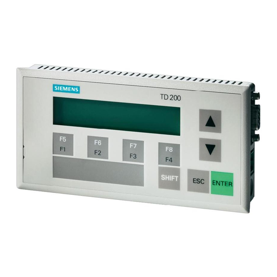
Page 12: Hardware Features
The TD 200 has nine keys. Five of these keys provide predefined, context-sensitive functions, and four keys provide user-defined functions. Spacers Self-adhesive spacers are included for mounting the TD 200 to a mounting surface. See Figure 1-4. SIMATIC TD 200 Operator Interface C79000-G7076-C205-04... -
Page 13: Td 200 Keyboard Features
If you press the SHIFT key along with, or prior to, pressing the F3 key, F3 sets the Mx.6 bit. Function key F4 sets the Mx.3 bit. If you press the SHIFT key along with, or prior to, pressing the F4 key, F4 sets the Mx.7 bit. SIMATIC TD 200 Operator Interface C79000-G7076-C205-04... -
Page 14: Installing The Td 200
1. Remove the three screws from the rear of the TD 200 using a flat-head screwdriver. See Figure 1-3. 2. Remove the backplate of the TD 200. Mounting Screws Figure 1-3 Removing the Three Mounting Screws SIMATIC TD 200 Operator Interface C79000-G7076-C205-04... -
Page 15: Mounting The Td 200
2. Fit the frontplate into the cutout you made in the mounting surface. 3. Secure the backplate onto the frontplate of the TD 200 using the screws you removed from the backplate. Tighten the screws. SIMATIC TD 200 Operator Interface C79000-G7076-C205-04... -
Page 16: Connecting The Communication Cable
Appendix B. Note The TD 200 defaults to address 1 and attempts to communicate to a CPU at address 2. See Section 3.8 to change the network address if other addresses are used. SIMATIC TD 200 Operator Interface C79000-G7076-C205-04... -
Page 17: Connecting A Power Cable
2.5 m (8.2 ft.). If you choose to connect the TD 200 to the CPU with a longer cable ( 2.5 m/8.2 ft.), use PROFIBUS components (see the SINEC IK10 Catalog). The power supply is available from your Siemens distributor. See Appendix A for part numbers. To CPU... - Page 18 Product Overview and Installation SIMATIC TD 200 Operator Interface C79000-G7076-C205-04...
-
Page 19: Configuring The Td 200
CPU, and then displays the message. Chapter Overview Section Description Page Starting the STEP 7–Micro/WIN TD 200 Configuration Wizard Creating a Sample Program 2-18 SIMATIC TD 200 Operator Interface C79000-G7076-C205-04... -
Page 20: Starting The Step 7-Micro/Win Td 200 Configuration Wizard
When you are finished, the wizard will generate the supporting data block code for you. To begin configuring TD 200 messages, click Next. < Prev Next > Cancel 1, 1 Figure 2-1 Accessing the TD 200 Configuration Wizard SIMATIC TD 200 Operator Interface C79000-G7076-C205-04... -
Page 21: Selecting Language And Bar Graph Character Set
Which national language would you like your TD 200 to support? English Would you like to enable the Bar Graph character set? < Prev Cancel Next > Figure 2-2 Wizard: Language and Character Set SIMATIC TD 200 Operator Interface C79000-G7076-C205-04... -
Page 22: Enabling Time-Of-Day, Force Function, And Password Protection
One M bit is set by the TD 200 each time the corresponding function key is pressed. Always reserve an M Area address even when your program does not utilize function keys. Valid address values for specific CPUs are defined in the SIMATIC S7-200 Programmable Controller System Manual . SIMATIC TD 200 Operator Interface C79000-G7076-C205-04... -
Page 23: Bits Set By Each Function Key
The update rate determines how often the TD 200 polls the CPU for messages to display. How often would you like the TD 200 to poll for messages? As fast as possible < Prev Cancel Next > Figure 2-5 Wizard: Function Key Memory Bits and Update Rate SIMATIC TD 200 Operator Interface C79000-G7076-C205-04... -
Page 24: Selecting Message Size And Number Of Messages
40 character message mode – displays one message at a time The TD 200 allows you to configure up to 80 messages. How many messages do you wish to configure? < Prev Next > Cancel Figure 2-6 Wizard: Message Size and Number of Messages SIMATIC TD 200 Operator Interface C79000-G7076-C205-04... -
Page 25: Specifying Parameter Block Address, Message Enable Address, And Message Location
You must now define where you would like the message information to reside in your data block. Starting byte for message information: < Prev Next > Cancel Figure 2-7 Wizard: Block Address, Enable Flags, and Message Location SIMATIC TD 200 Operator Interface C79000-G7076-C205-04... -
Page 26: Creating A Text-Only Message
Embedded Data... <Previous Message Next Message > message. VB40 is the address of MSG1, VB80 would be displayed for MSG2, and so on. < Prev Finish Cancel Figure 2-8 Wizard: 40-Character Message SIMATIC TD 200 Operator Interface C79000-G7076-C205-04... -
Page 27: Embedding Data Values In A Text Message
A leading zero is used for all fractional numbers (for example, 0.5). Real numbers are displayed with the number of decimal places you specify. The value is rounded to the specified decimal place. SIMATIC TD 200 Operator Interface C79000-G7076-C205-04... -
Page 28: Wizard: Embedding Variable Data Value In A Message
Message enabled bit: V12.6 Embedded Data... <Previous Message Next Message > Place cursor at the correct position and click “Embedded Data...” < Prev Cancel Finish Figure 2-9 Wizard: Embedding Variable Data Value in a Message SIMATIC TD 200 Operator Interface 2-10 C79000-G7076-C205-04... -
Page 29: Formatting The Embedded Data Value
Word Unsigned Double Word User must acknowledge message Is the user allowed to edit this data? Address of Data Value: VW98 Delete Cancel Figure 2-10 TD 200 Message: Creating a Word Embedded Data SIMATIC TD 200 Operator Interface 2-11 C79000-G7076-C205-04... -
Page 30: Wizard: Embedded Data Value Place Holder In Message
If checked, the operator must enter a password before being allowed to edit the data value. You selected the password at the beginning of the configuration process (see Figure 2-3); it is shown in the Password for Edit field. SIMATIC TD 200 Operator Interface 2-12 C79000-G7076-C205-04... -
Page 31: Embedded Data: Making The Data Editable And Password Protected
N E W S E T P O I Message beginning address: VB80 Message enabled bit: V12.6 Embedded Data... <Previous Message Next Message > < Prev Cancel Finish Figure 2-13 Wizard: Completed Second Message SIMATIC TD 200 Operator Interface 2-13 C79000-G7076-C205-04... -
Page 32: Creating A Message That Requires Acknowledgement
Message enabled bit: V12.5 Embedded Data... <Previous Message Next Message > Place cursor on the 39th position and click “Embedded Data...” < Prev Finish Cancel Figure 2-14 Wizard: Embedding Data to Require Acknowledgement SIMATIC TD 200 Operator Interface 2-14 C79000-G7076-C205-04... -
Page 33: Embedded Data: Requiring Acknowledgement Of Message
Digits to the right of the decimal None Signed Word Unsigned Double Word User must acknowledge message Is the user allowed to edit this data? Delete Cancel Figure 2-15 Embedded Data: Requiring Acknowledgement of Message SIMATIC TD 200 Operator Interface 2-15 C79000-G7076-C205-04... -
Page 34: Wizard: Message Requires Acknowledgement
Message enabled bit: V12.6 Acknowledgement notification bit: V78.1 Embedded Data... <Previous Message Next Message > Note: The address of the acknowledge- notification bit is displayed. < Prev Finish Cancel Figure 2-16 Wizard: Message Requires Acknowledgement SIMATIC TD 200 Operator Interface 2-16 C79000-G7076-C205-04... -
Page 35: Viewing The Td 200 Parameter Block And Messages
// No Edit; Acknowledgement Notification V158.1; No Password VB159 16#00 // No Data; 0 Digits to the right of the decimal; // END TD200_BLOCK 0 Figure 2-17 Data Block Editor Showing a Sample TD 200 Parameter Block SIMATIC TD 200 Operator Interface 2-17 C79000-G7076-C205-04... -
Page 36: Creating A Sample Program
Press ENTER to edit the setpoint. Press ENTER again to go to the acknowledge message. Press ENTER to acknowledge the third message. Press F2 to enable all three messages at once. Press F3 to disable all the messages. SIMATIC TD 200 Operator Interface 2-18 C79000-G7076-C205-04... -
Page 37: Sample Program In The Ladder And Statement List Editors
Network 4 V158.1 V158.1 MOV_B 16#80 VB12 Network 5 M0.1 MOV_B 16#E0 VB12 M0.1 Network 6 M0.2 MOV_B VB12 M0.2 Network 7 Figure 2-18 Sample Program in the Ladder and Statement List Editors SIMATIC TD 200 Operator Interface 2-19 C79000-G7076-C205-04... - Page 38 Configuring the TD 200 SIMATIC TD 200 Operator Interface 2-20 C79000-G7076-C205-04...
-
Page 39: Operating The Td 200
Using the Display Message Mode Using the Menu Mode Viewing Messages Viewing CPU Status Menu Forcing I/O Setting Time and Date in the CPU 3-13 Releasing the Password 3-15 Using the TD 200 Setup Menu Option 3-16 SIMATIC TD 200 Operator Interface C79000-G7076-C205-04... -
Page 40: Using The Display Message Mode
1. Press the DOWN arrow. The TD 200 displays the next lower priority message(s). 2. Press the UP arrow. The TD 200 displays the next higher priority message(s). 3. Press any key (except the UP or DOWN arrows). The TD 200 exits the scrolling mode. SIMATIC TD 200 Operator Interface C79000-G7076-C205-04... -
Page 41: Editing A Value
CPU (by pressing the ENTER key after modifying the value) are displayed; any value that was modified but not saved is overwritten by the previous (original) value. SIMATIC TD 200 Operator Interface C79000-G7076-C205-04... -
Page 42: Acknowledging A Message
Messages that do not require acknowledgement or editing are replaced on the display if a higher priority message is enabled by the S7-200 CPU. For more information on acknowledging a message, see Section D.5. SIMATIC TD 200 Operator Interface C79000-G7076-C205-04... -
Page 43: Using The Menu Mode
The TD 200 exits the Menu mode when you press ESC during the display of one of the menu items. Also, the TD 200 exits the Menu mode automatically after one minute and returns to the Display Message mode if you have not pressed any keys. SIMATIC TD 200 Operator Interface C79000-G7076-C205-04... -
Page 44: Viewing Messages
Pressing ESC at any time when you are viewing messages aborts the message display and returns you to the Display Message mode. The TD 200 automatically returns to the Display mode after one minute if no keys are pressed. SIMATIC TD 200 Operator Interface C79000-G7076-C205-04... -
Page 45: Viewing Cpu Status Menu
If fatal and/or non-fatal errors are present, use the following process to view the fatal and non-fatal errors. Action Display The TD 200 scrolls down the list of errors that are present. ERRORS PRESENT SIMATIC TD 200 Operator Interface C79000-G7076-C205-04... -
Page 46: Fatal Error Messages
– HSC setup and execution errors – Attempting to execute an illegal instruction (ENI, DISI, or HDEF) inside an interrupt routine – Subroutine nesting errors – TODW data errors – Simultaneous XMT and RCV errors SIMATIC TD 200 Operator Interface C79000-G7076-C205-04... -
Page 47: Forcing I/O
Pressing ESC at any time while you are forcing I/O returns you to the Display Message mode. The TD 200 automatically returns to the Display Message mode after one minute if no keys are pressed. SIMATIC TD 200 Operator Interface C79000-G7076-C205-04... -
Page 48: Entering A Password
CPU. If the password is incorrect, the TD 200 displays the message shown in Figure 3-3. SIEMENS TD 200 SHIFT ENTER Figure 3-3 Incorrect Password Display Correcting a Password Press ESC and repeat the steps for entering a password. SIMATIC TD 200 Operator Interface 3-10 C79000-G7076-C205-04... -
Page 49: Selecting A Force I/O Option
Such a failure could result in the CPU going into fatal error mode upon next power-up. To clear the fatal error, rewrite the force information to the CPU or unforce all I/O points, then power cycle the CPU to clear the fatal error. SIMATIC TD 200 Operator Interface 3-11 C79000-G7076-C205-04... -
Page 50: Forcing And Unforcing An I/O Point
If you wish to change the force status, press ESC to return the cursor to the I/O address. With the cursor on the I/O address, press ESC to return to the Force I/O menu. SIMATIC TD 200 Operator Interface 3-12... -
Page 51: Setting Time And Date In The Cpu
Pressing ESC at any time while you are setting the time and date returns you to the Display Message mode. The TD 200 automatically returns to the Display Message mode after one minute if no keys are pressed. SIMATIC TD 200 Operator Interface 3-13 C79000-G7076-C205-04... -
Page 52: Editing The Time And Date
Pressing ESC with the cursor on the day field returns you to the Display Message mode. Note The TD 200 does not check for illegal dates. Illegal dates can be written to the CPU. SIMATIC TD 200 Operator Interface 3-14 C79000-G7076-C205-04... -
Page 53: Releasing The Password
The TD 200 enters the Menu mode. MENU MODE: VIEW MESSAGES The TD 200 scrolls down the menu options MENU MODE: four times. RELEASE PASSWORD The TD 200 returns to the ENTER password-protected operations. SIMATIC TD 200 Operator Interface 3-15 C79000-G7076-C205-04... -
Page 54: Using The Td 200 Setup Menu Option
TD 200. TD 200 ADDRESS Note Pressing ESC at any time while setting the network address for the TD 200 aborts the edit and returns the cursor to the left-most character of the line. SIMATIC TD 200 Operator Interface 3-16 C79000-G7076-C205-04... -
Page 55: Selecting The Cpu Address
SETUP MENU: the CPU. CPU ADDRESS Note Pressing ESC at any time while setting the network address for the CPU aborts the edit and returns the cursor to the left-most character of the line. SIMATIC TD 200 Operator Interface 3-17 C79000-G7076-C205-04... -
Page 56: Entering The Parameter Block Address
PARM ADDRESS Note Pressing ESC at any time while entering the address of the parameter block aborts the edit and returns the cursor to the left-most character of the line. SIMATIC TD 200 Operator Interface 3-18 C79000-G7076-C205-04... -
Page 57: Selecting The Baud Rate
ENTER ENTER SETUP MENU: BAUD RATE 19.2K Note Pressing ESC at any time while setting the baud rate aborts the edit and returns the cursor to the left-most character of the line. SIMATIC TD 200 Operator Interface 3-19 C79000-G7076-C205-04... - Page 58 Operating the TD 200 SIMATIC TD 200 Operator Interface 3-20 C79000-G7076-C205-04...
-
Page 59: Creating Sample Programs
ASCII text. A TD 200 and a CPU 214 are used to create a clock. The second program illustrates the bar graph character set. Chapter Overview Section Description Page Using a Text Message to Create a Clock for a CPU 214 Using the Bar Graph Character Set SIMATIC TD 200 Operator Interface C79000-G7076-C205-04... -
Page 60: Using A Text Message To Create A Clock For A Cpu
When you are finished, the wizard will generate the supporting data block code for you. To begin configuring TD 200 messages, click Next. < Prev Next > Cancel 1, 1 Figure 4-1 Accessing the TD 200 Configuration Wizard SIMATIC TD 200 Operator Interface C79000-G7076-C205-04... -
Page 61: Data Block Of The Clock Message
// Set the starting address for message enable bits to VW12 // MESSAGE 1 // Message Enable Bit V12.7 VB20 ’ – – : : ’ // END TD200_BLOCK 0 Figure 4-2 Data Block of the Clock Message SIMATIC TD 200 Operator Interface C79000-G7076-C205-04... -
Page 62: Sample Program For Creating A Clock
VB105, VB38, 2 // ...enable the message VB101 NETWORK 2 VB20 MEND VB102 VB23 VB100 VB26 VB103 VB32 VB104 VB35 VB105 VB38 MOV_B 16#80 VB12 Network 2 Figure 4-3 Sample Program for Creating a Clock SIMATIC TD 200 Operator Interface C79000-G7076-C205-04... -
Page 63: Using The Bar Graph Character Set
// Set the starting address for message enable bits to VW12 // MESSAGE 1 // Message Enable Bit V12.7 VB20 ’ BAR GRAPH SAMPLE ’ // END TD200_BLOCK 0 Figure 4-4 Data Block of the Bar Graph Sample Program SIMATIC TD 200 Operator Interface C79000-G7076-C205-04... - Page 64 Figure 4-5, download the data block and the program to a CPU, and place the CPU in RUN mode. Adjust potentiometer 0 to display the bar graph. Note This example does not produce an exact representation of the analog potentiometer value. The partial bars are approximate. SIMATIC TD 200 Operator Interface C79000-G7076-C205-04...
-
Page 65: Sample Program For Creating A Bar Graph
// store partial block to buffer MOV_B NETWORK 2 SMB28 MEND MOV_B 16#FF VB19 BLKMOV_B VB19 VB20 SHR_DW ADD_I 16#FA MOV_DW &VB20 ADD_I MOV_B *AC2 Network 2 Figure 4-5 Sample Program for Creating a Bar Graph SIMATIC TD 200 Operator Interface C79000-G7076-C205-04... - Page 66 Creating Sample Programs SIMATIC TD 200 Operator Interface C79000-G7076-C205-04...
-
Page 67: Specifications And Reference
ASCII characters and special ALT key combinations for entering international and special characters. Chapter Overview Section Description Page Specifications for Model Number 6ES7 272–0AA00–0YA0 ASCII Characters ALT Key Combinations for International and Special Characters SIMATIC TD 200 Operator Interface C79000-G7076-C205-04... -
Page 68: Specifications For Model Number 6Es7 272-0Aa00-0Ya0
(IEC 801–2; ESD) without additional parts Safety Optional Power Supply VDE Rating VDE 0805 EN 60950 IEC 6ES7 705–0AA00–1AA0 220 V 6ES7 705–0AA00–1BA0 115 V Noise Emission < 45 dB(A) according to DIN 45635 (no fan) SIMATIC TD 200 Operator Interface C79000-G7076-C205-04... -
Page 69: Ascii Characters
ä changed. See æ Section D.2 for Æ information about å selecting the ö alternate ASCII Å – characters. ö ü α ß ¢ ñ ö Ω ü Σ Π < SIMATIC TD 200 Operator Interface C79000-G7076-C205-04... -
Page 70: Alt Key Combinations For International And Special Characters
Alt-0195 (left arrow Å Alt-0143 Alt-0180 (right arrow Alt-0248 Alt-0200 (single bar) α Alt-0224 Alt-0201 (double bar) ß Alt-0225 Alt-0202 (triple bar) Alt-0238 Alt-0203 (four bars) Alt-0230 Alt-0204 (five bars) Alt-0229 Alt-0194 (up arrow) ¢ Alt-0155 SIMATIC TD 200 Operator Interface C79000-G7076-C205-04... -
Page 71: Multiple Cpu Configurations
The TD 200s act as network masters and do not interfere with one another. The CPUs can be either masters or slaves on the network. Chapter Overview Section Description Page Configuring for Multiple CPU Communication Building a TD/CPU Cable SIMATIC TD 200 Operator Interface C79000-G7076-C205-04... -
Page 72: A Typical Multiple Cpu Network
To additional CPUs Figure B-1 A Typical Multiple CPU Network Network connectors are available from Siemens. Using these connectors allows you to isolate the CPUs from one another (the 24 VDC), but still allows you to power the TD 200 from the CPU. - Page 73 When you connect a PG 702 to a network of CPUs and TD 200s, the PG 702 does not function if there are more than three TD 200s. Note The display update time slows as more TD 200s are added to the network. SIMATIC TD 200 Operator Interface C79000-G7076-C205-04...
-
Page 74: Building A Td/Cpu Cable
The maximum length for the cable is 1200 meters. TD 200 Side S7-200 Side Transmit/Receive Data + Transmit/Receive Data + Logic Ground Logic Ground Shield Transmit/Receive Data – Transmit/Receive Data – Figure B-3 TD/CPU Cable without Power Connections SIMATIC TD 200 Operator Interface C79000-G7076-C205-04... -
Page 75: Troubleshooting
Some other master has locked the Wait — it disappears in a few CPU by uploading or downloading a seconds. program to that CPU. CPU IN STOP MODE RUN/STOP switch is in STOP. Put CPU in RUN mode. SIMATIC TD 200 Operator Interface C79000-G7076-C205-04... - Page 76 Troubleshooting SIMATIC TD 200 Operator Interface C79000-G7076-C205-04...
-
Page 77: Td 200 Parameters And Messages
Chapter Overview Section Description Page TD 200 Parameter Block Building the Parameter Block Formatting Messages Embedding Data Values in a Text Message D-11 Understanding Message Types D-20 Editing Variables with the TD 200 D-22 SIMATIC TD 200 Operator Interface C79000-G7076-C205-04... -
Page 78: Understanding How Messages Are Displayed
TD 200 Unit 1 Parameter block at VW0 VW40 Parameter block for unit 2 SIEMENS TD 200 SIMATIC S7-200 TD 200 Unit 2 Parameter block at VW40 Figure D-1 Displaying Different Messages on Two TD 200 Units SIMATIC TD 200 Operator Interface C79000-G7076-C205-04... -
Page 79: Description Of The Parameter Block Format
Disable/Enable Time-of-Day Clock Menu Disable/Enable Edit Password. Select Standard or Alternate (Bar Graph) Note: If enabled, password is stored in bytes 10 and 11 character set of extended parameter block. Figure D-2 TD 200 Parameter Block SIMATIC TD 200 Operator Interface C79000-G7076-C205-04... -
Page 80: Building The Parameter Block
5 – Spanish 2 – German 6 – Not defined 3 – French 7 – Not defined * Values given as hexadecimal values Figure D-3 Information Contained in Byte 2 of the TD 200 Parameter Block SIMATIC TD 200 Operator Interface C79000-G7076-C205-04... -
Page 81: Number Of Messages Byte 4
Figure D-4 Information Contained in Byte 3 of the TD 200 Parameter Block Number of Messages Byte 4 Byte 4 of the TD 200 parameter block defines the number of messages you have configured. The TD 200 accepts values 0 to 80. SIMATIC TD 200 Operator Interface C79000-G7076-C205-04... -
Page 82: Prioritizing Messages
Byte 5 of the TD 200 parameter block defines the address of the byte of M bits. Valid address values for specific CPUs are defined in the SIMATIC S7-200 Programmable Controller System Manual . SIMATIC TD 200 Operator Interface C79000-G7076-C205-04... -
Page 83: Message Address Bytes 6 And 7
For example: if you assign VB50 as the message-enable address, the first message is enabled by bit V50.7, the second message by V50.6, the third message by V50.5, and the eighth message by V50.0. SIMATIC TD 200 Operator Interface C79000-G7076-C205-04... -
Page 84: Edit Password Byte 10 And 11 (Optional
3, you must enter a password in bytes 10 and 11; however, if you do not enable password protection in byte 3, you are not required to store a password in bytes 10 and 11. SIMATIC TD 200 Operator Interface C79000-G7076-C205-04... -
Page 85: Formatting Messages
20-character message can be formatted in the CPU and displayed on the TD 200. How the Message Looks in V Memory Value Text 1 Text 2 Format Variable Word Data (word) How the Message Is Displayed on the TD 200 Figure D-7 Twenty-Character Message Format SIMATIC TD 200 Operator Interface C79000-G7076-C205-04... -
Page 86: Forty-Character Message Format
Value Value Value Text 3 Format Variable Text 4 Format Variable Text 5 Word Data Word Data (word) (word) How the Message Is Displayed on the TD 200 Figure D-8 Forty-Character Message Format SIMATIC TD 200 Operator Interface D-10 C79000-G7076-C205-04... -
Page 87: Embedding Data Values In A Text Message
Format Word with an Optional Double Word Value or Real (Floating-Point) Value Byte 0 Byte 1 Byte 2 Byte 3 Byte 4 Byte 5 MSB of LSB of MSB of LSB of Format Format DWord DWord Figure D-9 Format Word Usage SIMATIC TD 200 Operator Interface D-11 C79000-G7076-C205-04... -
Page 88: Defining The Data Value Format
MSB of LSB of Format Format Data Data E P EN A – Acknowledgement 0 – No acknowledgement 1 – Acknowledgement required Figure D-11 Acknowledgement Bit of Byte 0 of the Format Word SIMATIC TD 200 Operator Interface D-12 C79000-G7076-C205-04... -
Page 89: Acknowledge-Notification Bit 1
MSB of LSB of Format Format Data Data A N – Acknowledge-Notification E P EN 0 – Not acknowledged 1 – Message Acknowledged Figure D-12 Acknowledge-Notification Bit of Byte 0 of the Format Word SIMATIC TD 200 Operator Interface D-13 C79000-G7076-C205-04... -
Page 90: Edit-Notification Bit 2
If an embedded value is set to allow editing, you must design your S7-200 program to check the edit-notification bit. When the embedded value is modified by the user, your program must read the value and take any necessary action with it. SIMATIC TD 200 Operator Interface D-14 C79000-G7076-C205-04... -
Page 91: Sample Program For Using The Edit-Notification Bit
// On each scan ... VW23 VW250 MOVWVW250,VW23 // copy the variable to the location of the Network # // embedded value. SM 0.0 MOV_W VW250 VW23 Figure D-15 Sample Program for Using the Edit-Notification Bit SIMATIC TD 200 Operator Interface D-15 C79000-G7076-C205-04... -
Page 92: Password Protection Bit 3
MSB of LSB of Format Format Data Data E – Edit-Allowed 0 – Edit not allowed E P EN 1 – Edit allowed Figure D-17 Edit-Allowed Bit of Byte 0 of the Format Word SIMATIC TD 200 Operator Interface D-16 C79000-G7076-C205-04... -
Page 93: Data Size/Format, And Decimal Bits 0, 1, 2 And
6 – Six digits to the right of the decimal point 7 – Seven digits to the right of the decimal point Figure D-18 Bit Values of Byte 1 of the Format Word SIMATIC TD 200 Operator Interface D-17 C79000-G7076-C205-04... - Page 94 Real (floating point) numbers are displayed with the number of decimal places that you specified (see Figure D-18). The value is rounded to the designated level of precision. For example, if one decimal place were specified for the value 12.567, the TD 200 would display “12.6”. SIMATIC TD 200 Operator Interface D-18 C79000-G7076-C205-04...
-
Page 95: Required Display Characters For Each Display Format
123456789.1 to 1 to 7 123.4567891 –1234567891 Signed DWord –123456789.1 to 1 to 7 –123.4567891 Up to 20 –1234567 Real DWord DWord (Floating (Floating 1 to 7 Up to 20 12345.6 to 0.0123456 Point) SIMATIC TD 200 Operator Interface D-19 C79000-G7076-C205-04... -
Page 96: Understanding Message Types
S7-200 CPU. An up or down arrow in the right-most character position indicates more messages. The operator can press either the UP or the DOWN arrow key to scroll through the other enabled messages. For more information about editing variables, see Section D.6. SIMATIC TD 200 Operator Interface D-20 C79000-G7076-C205-04... -
Page 97: Acknowledgement, Edits Allowed
CPU. The TD 200 then displays the message and causes the entire message to flash to notify the operator that the message is present and must be acknowledged. For more information about editing variables, see Section D.6. SIMATIC TD 200 Operator Interface D-21 C79000-G7076-C205-04... -
Page 98: Editing Variables With The Td
– To reset the variable to 0, press the SHIFT ENTER keys. 5. Press ENTER to write the updated variable to the CPU. On the same program scan, the edit-notification bit is set in the format word corresponding to the variable being edited. SIMATIC TD 200 Operator Interface D-22 C79000-G7076-C205-04... -
Page 99: Aborting An Edit
CPU.) If the message was configured for acknowledgement, the message starts to flash again, since the edit was not completed. Note An edit is automatically aborted if you do not press a key after one minute. SIMATIC TD 200 Operator Interface D-23 C79000-G7076-C205-04... - Page 100 TD 200 Parameters and Messages SIMATIC TD 200 Operator Interface D-24 C79000-G7076-C205-04...
- Page 101 Embedded data values (text messages), format- Configuration Wizard, D-1 ting, 2-11, D-11–D-19 introduction, 2-2 Embedded variables, acknowledging and edit- CPU address, selecting, 3-17 ing, 3-3–3-5, D-22–D-24 Error messages fatal, 3-8 non-fatal, 3-8 viewing, 3-7 Data size/format bits, D-17–D-20 SIMATIC TD 200 Operator Interface Index-1 C79000-G7076-C205-04...
- Page 102 Language, operator interface, 2-3, D-4 Mode of operation display message, 3-2 menu, 3-5 Mounting, TD 200, 1-4 M area address, parameter block, 2-4, D-6 Manuals, iv finding topics in manual set, iv Menu language, 2-3 SIMATIC TD 200 Operator Interface Index-2 C79000-G7076-C205-04...
- Page 103 Viewing CPU status menu, 3-7 external supply, 1-7 Viewing messages menu, 3-6 TD/CPU cable, 1-7 Program, sample generating a bar graph, 4-5 using text message to create a clock for CPU 214, 4-2 SIMATIC TD 200 Operator Interface Index-3 C79000-G7076-C205-04...
- Page 104 Index SIMATIC TD 200 Operator Interface Index-4 C79000-G7076-C205-04...
- Page 105 Please check any industry that applies to you: Automotive Pharmaceutical Chemical Plastic Electrical Machinery Pulp and Paper Food Textiles Instrument and Control Transportation Nonelectrical Machinery Other _ _ _ _ _ _ _ _ _ _ _ Petrochemical SIMATIC TD 200 Operator Interface C79000-G7076-C205-04...
- Page 106 _ _ _ _ _ _ _ _ _ _ _ _ _ _ _ _ _ _ _ _ _ _ _ _ _ _ _ _ _ _ _ _ _ _ _ SIMATIC TD 200 Operator Interface...