Table of Contents
Advertisement
Quick Links
SITOP power supply
Power supply system PSU8600
Manual
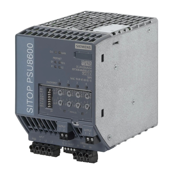
SITOP PSU8600 24 V DC/20 A
6EP3436-8SB00-2AY0
SITOP PSU8600 24 V DC/40 A
6EP3437-8SB00-2AY0
SITOP CNX8600 4 x 5 A
6EP4436-8XB00-0CY0
SITOP CNX8600 4 x 10 A
6EP4437-8XB00-0CY0
SITOP BUF8600 100 ms/40 A
6EP4297-8HB00-0XY0
SITOP BUF8600 300 ms/40 A
6EP4297-8HB10-0XY0
SITOP BUF8600 4 s/40 A
6EP4293-8HB00-0XY0
SITOP BUF8600 10 s/40 A
6EP4295-8HB00-0XY0
05.2017
A5E36758446-3-76
___________________
Overview
___________________
Safety instructions
___________________
Description, device design,
dimension drawing
___________________
Operator control at the
device
___________________
Installation and maintenance
___________________
Mounting position, mounting
clearances
___________________
Installation
___________________
Engineering and remote
access
___________________
Troubleshooting
___________________
Technical data
___________________
Safety, approvals, EMC
___________________
Environmental conditions
___________________
Applications
___________________
Environment
___________________
Service & support
1
2
3
4
5
6
7
8
9
10
11
12
13
14
Advertisement
Table of Contents

Related Manuals for Siemens PSU8600


Summary of Contents for Siemens PSU8600
- Page 1 ___________________ Engineering and remote access ___________________ Troubleshooting ___________________ Technical data ___________________ Safety, approvals, EMC SITOP PSU8600 24 V DC/20 A ___________________ 6EP3436-8SB00-2AY0 Environmental conditions SITOP PSU8600 24 V DC/40 A 6EP3437-8SB00-2AY0 ___________________ SITOP CNX8600 4 x 5 A 6EP4436-8XB00-0CY0 Applications...
-
Page 2: Legal Information
Note the following: WARNING Siemens products may only be used for the applications described in the catalog and in the relevant technical documentation. If products and components from other manufacturers are used, these must be recommended or approved by Siemens. Proper transport, storage, installation, assembly, commissioning, operation and maintenance are required to ensure that the products operate safely and without any problems. -
Page 3: Overview
Overview The SITOP PSU8600 power supply system is the high-performance, regulated technology power supply system for automated plants and machines. The key benefits of the product include: ● Wide-range input, which allows them to be connected to almost all 3-phase line supplies around the world ●... - Page 4 10 s/40 A buffer module 6EP4295-8HB00-0XY0 Validity This manual provides information on the following products: ● Basic device SITOP PSU8600 24 V DC/20 A PN Article number: 6EP3436-8SB00-2CY0 Product state: 1 Firmware version: V1.2 Functional expansion with respect to the previous version (PS: 1, FW: V1.1): –...
- Page 5 – None ● Buffer module SITOP BUF8600 10 s/40 A Article number: 6EP4295-8HB00-0XY0 Product state: 1 Firmware version: V1.2 Functional expansion with respect to the previous version (PS: 1, FW: V1.1): – None Power supply system PSU8600 Manual, 05.2017, A5E36758446-3-76...
- Page 6 Overview Power supply system PSU8600 Manual, 05.2017, A5E36758446-3-76...
-
Page 7: Table Of Contents
Overview..............................3 Safety instructions ..........................13 Safety instructions for explosive environments/zones ............14 1.1.1 Basic SITOP PSU8600 device ....................14 1.1.2 Expansion modules SITOP CNX8600 ..................14 Description, device design, dimension drawing..................15 Description of the basic devices ..................... 15 Description of the expansion modules .................. - Page 8 Other mounting positions ..................... 101 5.2.1 Basic device SITOP PSU8600 20 A ..................101 5.2.2 Basic device SITOP PSU8600 20 A and supplementary modules ........103 5.2.3 Basic device SITOP PSU8600 40 A ..................105 5.2.4 Basic device SITOP PSU8600 40 A and supplementary modules: ........107 Installation ............................
- Page 9 Table of contents 7.4.4 Assigning a SITOP PSU8600 to a controller ................ 127 7.4.5 Assigning supplementary modules to the SITOP PSU8600 basic device ......128 7.4.6 Parameter assignment ......................131 7.4.6.1 Parameters of the basic units and the supplementary modules ........... 131 7.4.6.2...
- Page 10 Preconditions ........................230 7.8.3 Activating the OPC UA server via the SITOP PSU8600 web server ........231 7.8.4 Establishing a connection to the OPC UA server of the SITOP PSU8600 ......232 7.8.5 Working with the OPC UA client ..................237 7.8.5.1 Displaying SITOP PSU8600 parameters ................
- Page 11 Protection against brief power failures .................. 305 12.2 Protecting against longer power failures ................306 12.3 Parallel connection to increase power rating ................ 307 12.4 Parallel connection for redundancy ..................308 Environment............................311 Service & support ..........................313 Power supply system PSU8600 Manual, 05.2017, A5E36758446-3-76...
- Page 12 Table of contents Power supply system PSU8600 Manual, 05.2017, A5E36758446-3-76...
-
Page 13: Safety Instructions
In order to protect plants, systems, machines and networks against cyber threats, it is necessary to implement – and continuously maintain – a holistic, state-of-the-art industrial security concept. Siemens’ products and solutions only form one element of such a concept. Customer is responsible to prevent unauthorized access to its plants, systems, machines and networks. -
Page 14: Safety Instructions For Explosive Environments/Zones
1.1 Safety instructions for explosive environments/zones Safety instructions for explosive environments/zones The devices comply with ATEX directive 2014/34/EU; EN 60079-0; EN 60079-15. 1.1.1 Basic SITOP PSU8600 device WARNING OPERATE POTENTIOMETERS OR SWITCHES IN NON-HAZARDOUS AREAS ONLY! 1.1.2 Expansion modules SITOP CNX8600... -
Page 15: Description, Device Design, Dimension Drawing
Description, device design, dimension drawing Description of the basic devices The basic devices SITOP PSU8600 are primary-clocked power supplies for connection to 3- phase AC line supplies. An electronically regulated DC voltage that can be set via a potentiometer is available at the output of the devices. The device output is isolated, no-load and short-circuit proof and has an electronic overload trip - or alternatively overload current limiting (constant current), which can be set using an additional potentiometer. - Page 16 Socket at the upper side of the device for the plug connection to optional expansion modules ⑪ Buttons of the outputs with LED display "ON/OFF/RST" ⑫ Voltage potentiometer ⑬ Current potentiometer ⑭ Selector switch, special functions from Power supply system PSU8600 Manual, 05.2017, A5E36758446-3-76...
-
Page 17: Description Of The Expansion Modules
GND terminal for optional ground connection to the basic device ⑤ "O.K LED." ⑥ DIN rail slider ⑦ Convection ⑧ Clearance above/below ⑨ LED buttons ON/OFF/RST ⑩ Voltage potentiometer U (V) ⑪ Current potentiometer I (A) Power supply system PSU8600 Manual, 05.2017, A5E36758446-3-76... -
Page 18: Description Of The Buffer Modules
400 V Buffer module 100 ms at 40 A 20 s 6EP4297-8HB00-0XY0 100 ms/40 A Buffer module 300 ms at 40 A 60 s 6EP4297-8HB10-0XY0 300 ms/40 A Power supply system PSU8600 Manual, 05.2017, A5E36758446-3-76... - Page 19 When the buffer module with electrolytic capacitors is completely charged (LED "O.K." lights green) power failures of 100 ms or 300 ms can be buffered with a load current of 40 A. The buffer time is correspondingly increased for lower load currents. Power supply system PSU8600 Manual, 05.2017, A5E36758446-3-76...
- Page 20 When the buffer module with double-layer capacitors is completely charged (LED "OK" lights green) power failures of 4 s or 10 s can be buffered with a load current of 40 A. The buffer time is correspondingly increased for lower load currents. Power supply system PSU8600 Manual, 05.2017, A5E36758446-3-76...
- Page 21 Brief interruption of the voltage at output 1 If a PC is operated on the PSU8600 power supply system, when the power fails, then this must be run down in plenty of time before the buffer time expires in order to avoid data being lost.
- Page 22 8 s can be buffered with a load current of 40 A. However, the "Longlife" mode is only possible when appropriately configured (STEP 7, OPC UA server, web server). You can find additional information in Chapter Engineering and remote access (Page 121) Power supply system PSU8600 Manual, 05.2017, A5E36758446-3-76...
-
Page 23: Connections And Terminal Designations
See the diagram under Description of the basic devices (Page 15) Terminal data 6EP3436-8SB00-2AY0: *1) Do not subject the end stop to high loads *2) Derating 18 A/60 °C or 20 A/50 °C Power supply system PSU8600 Manual, 05.2017, A5E36758446-3-76... - Page 24 Class B is maintained for PROFINET. Note The Ethernet/PROFINET connection to the basic devices of the PSU8600 power supply is optimized for use of the "Industrial Ethernet FastConnect RJ45 plugs 2x2" in an industrial design that is insensitive to noise and interference.
-
Page 25: Expansion Modules
Plug-in terminal with three screw connections Ground terminal GND See the diagram under Description of the expansion modules (Page 17) Terminal data 6EP4436-8XB00-0CY0, 6EP4437-8XB00-0CY0: *1) Do not subject the end stop to high loads Power supply system PSU8600 Manual, 05.2017, A5E36758446-3-76... -
Page 26: Buffer Modules
Control contact ON X1, X2 connection ⑤ Signaling contact "Sufficient buffer readiness" READY 13, 14 ⑥ Signaling contact "Buffering" OK 23, 24 See the diagram under Description of the buffer modules (Page 18) Terminal data 6EP4293-8HB00-0XY0, 6EP4295-8HB00-0XY0: Power supply system PSU8600 Manual, 05.2017, A5E36758446-3-76... -
Page 27: Operator Controls
Description, device design, dimension drawing 2.5 Operator controls Operator controls 2.5.1 Basic devices There are two main operating areas at the SITOP PSU8600 basic devices. ① ② ③ ● LED buttons and potentiometers ( The potentiometers are used to set the output voltage and response threshold of the output current. - Page 28 When required, this plastic cover can be sealed to prevent the operating elements being actuated by unauthorized personnel. For sealing, the sealing wire can be routed through an opening in the plastic cover and housing, as shown in the diagram below. Power supply system PSU8600 Manual, 05.2017, A5E36758446-3-76...
- Page 29 ELECTRONIC SHUTDOWN and CONSTANT CURRENT operating modes (Page 66) Setting the on delay (Page 68) Setting the output characteristic (Page 71) Activate the web server for the MANUAL operating mode on the module (Page 73) Power supply system PSU8600 Manual, 05.2017, A5E36758446-3-76...
-
Page 30: Expansion Modules
Switches in and switches out the various outputs, or resets the particu- "ON/OFF/RST" lar outputs after an electronic shutdown; see Switching an output on and off (Page 57) as well as Overload shutdown and carrying out a reset (Page 58). Power supply system PSU8600 Manual, 05.2017, A5E36758446-3-76... - Page 31 See also Overload shutdown and carrying out a reset (Page 58) Setting the output voltage and response threshold value of the output current (Page 55) Power supply system PSU8600 Manual, 05.2017, A5E36758446-3-76...
-
Page 32: Displays
Basic devices Labeling Signal type Signaling ① Device status ② Mode ③ Group error ④ RUN/STOP ⑤ P1/P2 Receive/transmit, port 1 and port 2 ⑥ ON/OFF/RST LED buttons Operating mode of the output Power supply system PSU8600 Manual, 05.2017, A5E36758446-3-76... - Page 33 MANUAL mode, i.e. setting directly at the device Flashing green (1/1) MANUAL mode; the mode has been changed in operation, settings directly at the device do not necessarily correspond to the active reference parameters. Power supply system PSU8600 Manual, 05.2017, A5E36758446-3-76...
- Page 34 Table 2- 7 LED "P1/P2" Signaling Device is OFF or is not connected with the controller Green Device connected with controller, no activity. Green/orange alternately Device connected with the controller, transmit/receive data (RX/TX). Power supply system PSU8600 Manual, 05.2017, A5E36758446-3-76...
- Page 35 Flashing red (1/1) Output shut down via control command (REMOTE operating mode) Yellow Output manually shut down using the button at the device Power supply system PSU8600 Manual, 05.2017, A5E36758446-3-76...
-
Page 36: Expansion Modules
Description, device design, dimension drawing 2.6 Displays 2.6.2 Expansion modules Labeling Signal type Signaling ① Device status ② ON/OFF/RST LED buttons Operating state of the particular output Power supply system PSU8600 Manual, 05.2017, A5E36758446-3-76... - Page 37 (power OFF/ON) Device shut down due to firmware update of another system component • Incorrect hardware configuration (REMOTE mode) • Yellow Power failure, buffer mode active Alternating, green/red Firmware being updated. (0.25/0.25) Power supply system PSU8600 Manual, 05.2017, A5E36758446-3-76...
- Page 38 Flashing red (1/1) Output shut down via control command (REMOTE mode) Yellow Output manually shut down using the button at the device Power supply system PSU8600 Manual, 05.2017, A5E36758446-3-76...
-
Page 39: Buffer Modules
Description, device design, dimension drawing 2.6 Displays 2.6.3 Buffer modules Labeling Signal type Signaling ① Device status Power supply system PSU8600 Manual, 05.2017, A5E36758446-3-76... - Page 40 Charge is still available after power supply voltage OFF • Device shut down due to firmware update of another system component • Incorrect hardware configuration (REMOTE mode) • Yellow Power failure, buffer mode active Alternating, green/red Firmware being updated (0.25/0.25) Power supply system PSU8600 Manual, 05.2017, A5E36758446-3-76...
-
Page 41: Signaling Contact/Control Contact
Basic unit has limited power output and expansion mod- • ule shut down due to system overload Output shut down due to overtemperature • Communication error between the basic unit and sup- • plementary module Expansion module failure • Power supply system PSU8600 Manual, 05.2017, A5E36758446-3-76... -
Page 42: Buffer Modules
The signal "Sufficient buffer readiness" refers exclusively to the SITOP BUF8600 buffer modules with double-layer capacitors in the system. Power supply system PSU8600 Manual, 05.2017, A5E36758446-3-76... - Page 43 SITOP BUF8600 buffer modules with electrolytic capacitors in the system are not taken into account. Signaling contact Explanation 23-24 open Power failure, system is buffered by the buffer module. (quiescent state) 23-24 closed Normal operation, buffer module is charged (if required). Power supply system PSU8600 Manual, 05.2017, A5E36758446-3-76...
-
Page 44: Block Diagrams
Description, device design, dimension drawing 2.8 Block diagrams Block diagrams Basic SITOP PSU8600 device Expansion modules SITOP CNX8600 Power supply system PSU8600 Manual, 05.2017, A5E36758446-3-76... - Page 45 Description, device design, dimension drawing 2.8 Block diagrams SITOP BUF8600 100 ms/40 A and SITOP BUF8600 300 ms/40 A buffer modules SITOP BUF8600 4 s/40 A and SITOP BUF8600 10 s/40 A buffer modules Power supply system PSU8600 Manual, 05.2017, A5E36758446-3-76...
-
Page 46: Dimensions And Weights
Description, device design, dimension drawing 2.9 Dimensions and weights Dimensions and weights SITOP PSU8600 basic devices Figure 2-2 Dimension drawing 6EP3436-8SB00-2AY0 front and left views Figure 2-3 Dimension drawing 6EP3436-8SB00-2AY0 view from below Power supply system PSU8600 Manual, 05.2017, A5E36758446-3-76... - Page 47 Description, device design, dimension drawing 2.9 Dimensions and weights Figure 2-4 Dimension drawing 6EP3437-8SB00-2AY0 front and left views Figure 2-5 Dimension drawing 6EP3437-8SB00-2AY0 view from below Power supply system PSU8600 Manual, 05.2017, A5E36758446-3-76...
- Page 48 Description, device design, dimension drawing 2.9 Dimensions and weights Expansion modules SITOP CNX8600 The dimensions are identical for both versions. Figure 2-6 Dimension drawing for 6EP4436-8XB00-0CY0 and 6EP4437-8XB00-0CY0 Power supply system PSU8600 Manual, 05.2017, A5E36758446-3-76...
- Page 49 Description, device design, dimension drawing 2.9 Dimensions and weights Buffer modules SITOP BUF8600 Figure 2-7 Dimension drawing 6EP4297-8HB00-0XY0 Power supply system PSU8600 Manual, 05.2017, A5E36758446-3-76...
- Page 50 Description, device design, dimension drawing 2.9 Dimensions and weights Figure 2-8 Dimension drawing 6EP4297-8HB10-0XY0 Power supply system PSU8600 Manual, 05.2017, A5E36758446-3-76...
- Page 51 Description, device design, dimension drawing 2.9 Dimensions and weights Figure 2-9 Dimension drawing 6EP4293-8HB00-0XY0 Figure 2-10 Dimension drawing 6EP4295-8HB00-0XY0 Power supply system PSU8600 Manual, 05.2017, A5E36758446-3-76...
- Page 52 Description, device design, dimension drawing 2.9 Dimensions and weights Dimensions and weights SITOP PSU8600 basic devices 6EP3436-8SS00-2AY0 6EP3437-8SB00-2AY0 Dimensions 80 × 125 × 150 125 x 125 x 150 (W × H × D) in mm Weight Approx. 1.78 kg 2.63 kg...
-
Page 53: Operator Control At The Device
MANUAL mode (see MANUAL and REMOTE operating modes (Page 61)). These operator controls are deactivated in the REMOTE operating mode. ① The output can be switched-on/switched-off and reset in any mode using button Power supply system PSU8600 Manual, 05.2017, A5E36758446-3-76... - Page 54 MANUAL mode (see MANUAL and REMOTE operating modes (Page 61)). These operator controls are deactivated in the REMOTE operating mode. ① The outputs can be switched-on/switched-off and reset in any mode using button Power supply system PSU8600 Manual, 05.2017, A5E36758446-3-76...
-
Page 55: Setting The Output Voltage And Response Threshold Value Of The Output Current
(the following diagram shows a setting for 15 V). Values between 4 and 28 Volt can be set. When supplied, the output voltage is set to 24 Volt. Power supply system PSU8600 Manual, 05.2017, A5E36758446-3-76... -
Page 56: Setting The Response Threshold Value Of The Output Current
For the expansion modules, depending on the type, values from 0.5 up to 5 A – or from 0.5 up to 10 A can be set. When delivered, the output current is set to the maximum possible value. Power supply system PSU8600 Manual, 05.2017, A5E36758446-3-76... -
Page 57: Switching An Output On And Off
The LED in the button is lit yellow when the output is manually shutdown. 1. You can switch off the output by pressing the button. The LED is lit green (output is switched on). Power supply system PSU8600 Manual, 05.2017, A5E36758446-3-76... -
Page 58: Overload Shutdown And Carrying Out A Reset
Using a reset, the output that has been automatically shut down can be switched-on again after a wait time of 5 seconds (LED "ON/OFF/RST" of the output flashes red). Power supply system PSU8600 Manual, 05.2017, A5E36758446-3-76... - Page 59 If, after a reset, the cause of the overload is still present, then the output is again automatically shut down according to the shutdown characteristics described previously. Before carrying out a reset, remove the cause of the overload to prevent a new shutdown. Power supply system PSU8600 Manual, 05.2017, A5E36758446-3-76...
- Page 60 Note The rising edge of the reset signal is evaluated; this means for an additional reset signal, the voltage level must first drop down to below 13 V. Power supply system PSU8600 Manual, 05.2017, A5E36758446-3-76...
-
Page 61: Manual And Remote Operating Modes
The switchover is made at the selector switch (see operator controls) with the ④ designation "REN" When delivered, DIP switch "REN" is in position "OFF" (operating mode MANUAL). Power supply system PSU8600 Manual, 05.2017, A5E36758446-3-76... - Page 62 DIP switches only become active after they have been actuated. Activating the REMOTE operating mode With the power supply system shut down, bring DIP switch "REN" into position "ON" (right), to activate the REMOTE operating mode. Power supply system PSU8600 Manual, 05.2017, A5E36758446-3-76...
- Page 63 (e.g. another output voltage)! Only switch over the operating mode when the power supply system is shut down, or before switching over in operation, ensure that the remote configuration corresponds to the actual device settings. Power supply system PSU8600 Manual, 05.2017, A5E36758446-3-76...
-
Page 64: Prioritization When The Power Fails
The switchover is made at selector switch (see operating controls) with the designation ⑤ "PRY 1" When delivered, DIP switch "PRY 1" is in position "OFF" (prioritization deactivated). Power supply system PSU8600 Manual, 05.2017, A5E36758446-3-76... - Page 65 1 of the basic unit has priority when buffering is required. Note Outputs 2...n, which are shut down when the power fails as output 1 has priority, are automatically switched-on again when the line supply returns. Power supply system PSU8600 Manual, 05.2017, A5E36758446-3-76...
-
Page 66: Electronic Shutdown And Constant Current Operating Modes
The switchover is made at the selector switch (see operator controls) with the designation ⑥ "UI-1" When delivered, DIP switch "UI-1" is in position "OFF" (mode ELECTRONIC SHUTDOWN). Power supply system PSU8600 Manual, 05.2017, A5E36758446-3-76... - Page 67 With the power supply system shut down, bring DIP switch "UI-1" into position "OFF" (left), to activate the ELECTRONIC SHUTDOWN mode. Constant current With the power supply system shut down, bring DIP switch "UI-1" into position "ON" (right), to activate the CONSTANT CURRENT mode. Power supply system PSU8600 Manual, 05.2017, A5E36758446-3-76...
-
Page 68: Setting The On Delay
3.7 Setting the on delay Setting the on delay In order to reduce the load on the overall SITOP PSU8600 power supply system as a result of simultaneous switch-on current peaks of the loads at the output of the basic device and at the outputs of the expansion modules, a switch on delay between the outputs can be selected when switching on. - Page 69 With the power supply system shut down, bring DIP switch "STDA" into position "ON" (right) and "STDB" into position "OFF" (left) in order to set the on delay to 25 ms. STDA STDB Power supply system PSU8600 Manual, 05.2017, A5E36758446-3-76...
- Page 70 "STDB" into position "ON" (right) in order to set the on delay to 100 ms. STDA STDB Load-optimized on delay With the power supply system shut down, bring both DIP switches "STDA" and "STDB" into position "ON" (right) to activate load-optimized on delay. STDA STDB Power supply system PSU8600 Manual, 05.2017, A5E36758446-3-76...
-
Page 71: Setting The Output Characteristic
3.8 Setting the output characteristic Setting the output characteristic For the standard output characteristic of the basic SITOP PSU8600 device, the output voltage is regulated to obtain a constant value independent of the output current. If the "soft" output characteristic is selected, then the output voltage slightly decreases as the output current increases. - Page 72 With increasing output current, in the range from no-load operation to rated output current, the output voltage linearly decreases by a value of approximately 1.2 V. Power supply system PSU8600 Manual, 05.2017, A5E36758446-3-76...
-
Page 73: Activate The Web Server For The Manual Operating Mode On The Module
Activate the web server for the MANUAL operating mode on the module The basic SITOP PSU8600 device has an integrated web server. This facilitates remote monitoring and diagnostics, for example to interrogate actual currents and messages/signals. Further, the actual module configuration can be viewed, if necessary changed and externally saved to a file and archived. - Page 74 Note No write access when the connection is active If the SITOP PSU8600 has an active connection to a control system (relation application), then the parameters can only be read-accessed. It is still possible to update the firmware - and save and delete the alarm list. If there is no active connection, then parameters can also be write accessed via the web server.
-
Page 75: Monitoring Functions
Monitoring functions 3.10.1 Overtemperature monitoring functions SITOP PSU8600 basic units and SITOP CNX8600 expansion modules have integrated overtemperature monitoring functions. The outputs are shut down if the internal temperature is inadmissibly high. Take the following steps after a shutdown as a result of an inadmissibly high internal temperature: 1. - Page 76 After the basic unit has cooled down, LED "OK" at the basic unit flashes red. 2. Switch-off the power supply for the SITOP PSU8600 for at least 10 seconds. 3. Switch on the supply voltage again. The complete system, including the state of the individual outputs, is brought into the operating state before the temperature shutdown.
-
Page 77: Phase Dissymmetry Monitoring
When a phase fails, the power supply system can be continually operated up to a maximum output current of 10 A or 20 A without any restrictions. The following signals indicate a shutdown due to phase asymmetry: Power supply system PSU8600 Manual, 05.2017, A5E36758446-3-76... - Page 78 LED "ON/OFF/RST" Reset of a shutdown due to phase dissymmetry 1. Switch off the supply voltage of the SITOP PSU8600 for at least 10 seconds, and remove the cause of the phase dissymmetry. 2. Switch on the supply voltage again.
-
Page 79: System Overload Monitoring
The outputs of the expansion modules are simultaneously shutdown. This operating state is signaled by: ① ● Green (in buffer operation, yellow) flashing LED "OK" at the basic unit ① ● Red LED "OK" of the expansion modules Power supply system PSU8600 Manual, 05.2017, A5E36758446-3-76... - Page 80 The LEDs in the buttons light up green. The outputs are switched-on again. 2. Alternatively, using a remote reset at terminal "RST", all outputs that have been shut down can be simultaneously switched-on again. Power supply system PSU8600 Manual, 05.2017, A5E36758446-3-76...
-
Page 81: Activating And Deactivating Buffer Operation
"X2" of one buffer module means that also the second buffer module is deactivated. This also applies to buffer modules with electrolytic capacitors, without control contact! Note The external circuit must meet the requirements relating to SELV circuits according to EN 60950-1. Power supply system PSU8600 Manual, 05.2017, A5E36758446-3-76... -
Page 82: Restore Factory Settings
Proceed as follows to reset the SITOP PSU8600 factory settings: 1. While the SITOP PSU8600 is operational, at the basic device, press the button for output 1 Keep the button pressed for approximately 5 s until the "MAN" LED at the device flashes green. -
Page 83: Installation And Maintenance
Use in hazardous zones When the SITOP PSU8600 power supply system is installed in a hazardous zone (Ex II 3G Ex nA nC IIC T4 Gc, Ex II 3G Ex nA IIC T4 Gc, Ex II 3G Ex nA IIC T5 Gc), then it must be accommodated in a distribution box with IP54 degree of protection or higher. -
Page 84: Rail Mounting
1. Position the device with the mounting rail guide at the upper edge of the standard mounting rail and press down to lock it into place. 2. If it is difficult to snap it into place, simultaneously press the slider using a screwdriver. Power supply system PSU8600 Manual, 05.2017, A5E36758446-3-76... - Page 85 – Insert the connecting plug into the socket provided at the basic unit. ① – Ensure that latch snaps into place. All additional supplementary modules can be connected in the same way to the supplementary module to the left. Power supply system PSU8600 Manual, 05.2017, A5E36758446-3-76...
-
Page 86: Permissible Hardware Configurations
Note Also when using four expansion modules, the maximum power of the system is 480 W or 960 W - and the maximum output current is 20 A or 40 A. Expansion modules, PSU8600 power supply system Type Article No. -
Page 87: Removal
2. Release all of the connections at the plug-in terminals, and if necessary, the PROFINET connection. 3. Release all of the connecting plugs at the basic unit and the supplementary modules being used. ① To do this, press latch and withdraw the connecting plug. Power supply system PSU8600 Manual, 05.2017, A5E36758446-3-76... - Page 88 7. If required, repeat steps 4 to 6 for each supplementary module. The following applies to BUF8600 buffer modules: WARNING After disconnecting from the supply, the device takes 30 minutes before it is safely discharged. Power supply system PSU8600 Manual, 05.2017, A5E36758446-3-76...
-
Page 89: Replacing Individual Components
2. Wait until all of the LEDs of the system have gone dark. 3. Release the connections at the plug-terminals of the component to be replaced. If the basic unit is replaced: When necessary, also release the PROFINET connection. Power supply system PSU8600 Manual, 05.2017, A5E36758446-3-76... - Page 90 4. Release the connecting plug at the component to be replaced. ③ 5. Release the connecting plug at the component to the right (if this is available). ④ ⑤ 6. Pull-up the slider using a screwdriver Power supply system PSU8600 Manual, 05.2017, A5E36758446-3-76...
- Page 91 2. Remove the plastic cover of the connecting socket (if there is an additional module at the right-hand side). 3. Connect the new component to the adjacent components using the connecting plug. Power supply system PSU8600 Manual, 05.2017, A5E36758446-3-76...
- Page 92 "manually shutdown" operating state. 6. Check all of the settings at the components to ensure that the correct values are set. 7. Commission the outputs by pressing on the relevant button. Power supply system PSU8600 Manual, 05.2017, A5E36758446-3-76...
-
Page 93: System Response For A Modified Hardware Configuration
4.6 System response for a modified hardware configuration System response for a modified hardware configuration The system response of the SITOP PSU8600 after modifying the system configuration is explained in this section. Modifying the system configuration involves changing, adding or removing individual components. -
Page 94: Behavior After Changing An Individual Component
"manually shutdown" (the LEDs of the outputs are lit yellow). The outputs are switched-on by pressing their associated buttons. Response after making a change and powering up in the REMOTE mode In this case, the system response depends on the specific case. Power supply system PSU8600 Manual, 05.2017, A5E36758446-3-76... - Page 95 ● The new module is deactivated (LED "O.K." flashes red, LEDs of the expansion module outputs are dark). You can activate the module by loading a correct configuration via the associated control system. See also Replacing individual components (Page 89) Power supply system PSU8600 Manual, 05.2017, A5E36758446-3-76...
-
Page 96: Response After Adding An Individual Component
Note By removing modules, it is possible that the previous module position of the remaining modules is changed. This can result in modules, whose position has changed, being deactivated and outputs shutdown. Power supply system PSU8600 Manual, 05.2017, A5E36758446-3-76... - Page 97 – Expansion modules with a lower power rating are deactivated (LED "O.K." flashes red, LEDs of the outputs are dark). You can activate these modules by loading a corrected configuration via the associated control system. Power supply system PSU8600 Manual, 05.2017, A5E36758446-3-76...
- Page 98 ● The module is deactivated (LED "O.K." flashes red, LEDs of the expansion module outputs are dark). You can activate the module by loading a correct configuration via the associated control system. Power supply system PSU8600 Manual, 05.2017, A5E36758446-3-76...
-
Page 99: Mounting Position, Mounting Clearances
No clearance is required at the side. Output current as a function of the ambient temperature Figure 5-1 Basic device SITOP PSU8600 20 A: Output current in the standard mounting position Figure 5-2 Basic device SITOP PSU8600 20 A and supplementary modules: Output current in the... - Page 100 Mounting position, mounting clearances 5.1 Standard mounting position Figure 5-3 Basic device SITOP PSU8600 40 A: Output current in the standard mounting position Figure 5-4 Basic device SITOP PSU8600 40 A and supplementary modules: Output current in the standard mounting position...
-
Page 101: Other Mounting Positions
Particularly when installing on a vertically fastened standard mounting rail, additional measures may be required, e.g. to prevent the device from slipping on the standard mounting rail. 5.2.1 Basic device SITOP PSU8600 20 A Figure 5-6 Mounting position 1 Figure 5-7... - Page 102 Mounting position, mounting clearances 5.2 Other mounting positions Figure 5-8 Mounting position 3 Figure 5-9 Mounting position 4 Figure 5-10 Mounting position 5 Power supply system PSU8600 Manual, 05.2017, A5E36758446-3-76...
-
Page 103: Basic Device Sitop Psu8600 20 A And Supplementary Modules
Mounting position, mounting clearances 5.2 Other mounting positions 5.2.2 Basic device SITOP PSU8600 20 A and supplementary modules Figure 5-11 Mounting position 1 Figure 5-12 Mounting position 2 Figure 5-13 Mounting position 3 Power supply system PSU8600 Manual, 05.2017, A5E36758446-3-76... - Page 104 Mounting position, mounting clearances 5.2 Other mounting positions Figure 5-14 Mounting position 4 Figure 5-15 Mounting position 5 Power supply system PSU8600 Manual, 05.2017, A5E36758446-3-76...
-
Page 105: Basic Device Sitop Psu8600 40 A
Mounting position, mounting clearances 5.2 Other mounting positions 5.2.3 Basic device SITOP PSU8600 40 A Figure 5-16 Mounting position 1 Figure 5-17 Mounting position 2 Figure 5-18 Mounting position 3 Power supply system PSU8600 Manual, 05.2017, A5E36758446-3-76... - Page 106 Mounting position, mounting clearances 5.2 Other mounting positions Figure 5-19 Mounting position 4 Figure 5-20 Mounting position 5 Power supply system PSU8600 Manual, 05.2017, A5E36758446-3-76...
-
Page 107: Basic Device Sitop Psu8600 40 A And Supplementary Modules
Mounting position, mounting clearances 5.2 Other mounting positions 5.2.4 Basic device SITOP PSU8600 40 A and supplementary modules: Figure 5-21 Mounting position 1 Figure 5-22 Mounting position 2 Figure 5-23 Mounting position 3 Power supply system PSU8600 Manual, 05.2017, A5E36758446-3-76... - Page 108 Mounting position, mounting clearances 5.2 Other mounting positions Figure 5-24 Mounting position 4 Figure 5-25 Mounting position 5 Power supply system PSU8600 Manual, 05.2017, A5E36758446-3-76...
-
Page 109: Installation
Line-side connection The SITOP PSU8600 power supply system is designed to be operated on 3-phase AC line systems (TN or TT line system according to IEC 60364-1) with a rated voltage of 3 AC 400 - 500 V, 50 - 60 Hz or IT line system with a rated voltage of 3 AC 400 - 500 V, 50 - 60 Hz. - Page 110 The protective conductor of the line supply must be connected at the "PE" terminal. Other country-specific regulations may have to be observed when installing the device. Also observe the information in Section Connections and terminal designations (Page 23). Power supply system PSU8600 Manual, 05.2017, A5E36758446-3-76...
-
Page 111: Connection On The Output Side
Note If the safety concept of the system specifies that the DC output circuit should be grounded (PELV), then the output voltage of the SITOP PSU8600 power supply system may be grounded. Ideally, the grounding at the output should be directly connected from terminal "0V" of the basic unit to a suitable connection point of the protective conductor system (PE) of the overall plant or system. -
Page 112: Connecting The Signaling Contact/Reset Terminal
The rising edge of the reset signal is evaluated; this means for an additional reset signal, the voltage level must first drop down to below 13 V. You can obtain more information about the overload shutdown and reset under Overload shutdown and carrying out a reset (Page 58) Power supply system PSU8600 Manual, 05.2017, A5E36758446-3-76... - Page 113 Installation 6.3 Connecting the signaling contact/reset terminal See also Connections and terminal designations (Page 23) Basic devices (Page 41) Power supply system PSU8600 Manual, 05.2017, A5E36758446-3-76...
-
Page 114: Establishing A Profinet Connection
For use in a hazardous zone, an Ethernet/PROFINET connector with strain relief must be used. Strain relief for use in a hazardous zone is implemented by using a Siemens IE FastConnect RJ45. The connection to the PROFINET network is realized using signal cables, connected to the Ethernet/PROFINET interface at the lower side of the device. - Page 115 Installation 6.4 Establishing a PROFINET connection Power supply system PSU8600 Manual, 05.2017, A5E36758446-3-76...
-
Page 116: Establishing An Additional Ground Connection
Only establish the connection between the power supply system and the common collection point of the 0 V potential via terminal "0V" of the basic device. See also Connections and terminal designations (Page 23). Power supply system PSU8600 Manual, 05.2017, A5E36758446-3-76... -
Page 117: Connecting The Control Contact And Signaling Contacts Of The Buffer Module
The signaling contacts are NO contacts, and allow information about the operating state of the buffer module to be processed further. Note The contact rating is 60 V DC/0.3 A The precise function of the signaling contacts is described under Buffer modules (Page 42). Power supply system PSU8600 Manual, 05.2017, A5E36758446-3-76... - Page 118 Installation 6.6 Connecting the control contact and signaling contacts of the buffer module You can obtain more information about the assignment of the signaling contacts under Connections and terminal designations (Page 23) Power supply system PSU8600 Manual, 05.2017, A5E36758446-3-76...
- Page 119 Installation 6.6 Connecting the control contact and signaling contacts of the buffer module Power supply system PSU8600 Manual, 05.2017, A5E36758446-3-76...
-
Page 121: Engineering And Remote Access
SIMATIC STEP 7 in the TIA Portal, it can be integrated into projects, parameterized and diagnosed. From SIMATIC STEP 7 V14 in the TIA Portal, versions of the SITOP PSU8600 – as well as the supplementary modules - are already integrated in the hardware catalog and can be directly used. -
Page 122: Overview Of Application Examples
(https://support.industry.siemens.com/cs/ww/en/view/102379345)) SIMATIC STEP 7 in the TIA Portal The SITOP PSU8600 power supply system can be used with SIMATIC STEP 7 in the TIA Portal from version SIMATIC STEP 7 V13 and higher. In SIMATIC STEP 7 in the TIA Portal, the SITOP PSU8600 basic device and its SITOP CNX8600 and SITOP BUF8600 supplementary modules can be integrated, parameterized and diagnosed in the projects. - Page 123 6. After the Support Package has been installed, the TIA Portal is reinitialized by clicking on "Restart". The installed devices are imported into the module catalog and can then be integrated in the project. You can find the SITOP PSU8600 in the hardware catalog under "Power Supplies\SITOP PSU\PSU8600". Note You can find additional information on installing HSP in the manual of your SIMATIC STEP 7 software.
-
Page 124: Gerätestammdaten-Datei (Gsd) Installieren
7.4.3 Inserting SITOP PSU8600 into a project To be able to use the SITOP PSU8600, you must assign an IO controller as IO device (SIMATIC S7 control). Further, the SITOP PSU8600 in the project can be equipped with one or several supplementary modules. - Page 125 SIMATIC STEP 7 software. Preconditions ● For SIMATIC STEP 7 V13 in the TIA portal: The HSP or the GSD of the SITOP PSU8600 has been installed. ● SIMATIC STEP 7 in the TIA Portal has been opened, and a project created with an IO controller (SIMATIC S7 control).
- Page 126 Alternatively, the module can also be added to the network view by double-clicking on the entry in the Hardware catalog. You have now inserted the SITOP PSU8600 into the project. The rectangle displayed in the network view symbolizes the SITOP PSU8600.
-
Page 127: Assigning A Sitop Psu8600 To A Controller
Assigning a SITOP PSU8600 to a controller To be able to use the SITOP PSU8600 you must assign an IO controller as IO device. 1. Click in the network view on the blue lettering "Not assigned" at the left next to the symbol of the PSU8600. -
Page 128: Assigning Supplementary Modules To The Sitop Psu8600 Basic Device
Assigning supplementary modules to the SITOP PSU8600 basic device Assigning a SITOP CNX8600 expansion module The number of outputs can be increased by using an expansion module. A SITOP PSU8600 basic device can be equipped with a maximum of four SITOP CNX8600 expansion modules. - Page 129 Parameterizing output 1 (Page 141). Assigning a buffer module SITOP BUF8600 A buffer module permits buffering when the power fails. A SITOP PSU8600 basic unit can be equipped with a maximum of two SITOP BUF8600 buffer modules.
- Page 130 Preconditions ● SIMATIC STEP 7 in the TIA Portal has been opened and a project has been created. ● A SITOP PSU8600 basic unit has been integrated in the project. Procedure 1. Select the SITOP PSU8600 in the Device view.
-
Page 131: Parameter Assignment
7.4.6.1 Parameters of the basic units and the supplementary modules The adjustable parameters of SITOP PSU8600 and the supplementary modules being used can be found in SIMATIC STEP 7 in the TIA Portal in the Inspector window under Properties if the appropriate device was selected. - Page 132 Define the dead time for buffering mode alarm. • Define the waiting time until short-time interruption. • Define the duration of short-time interruption. • PROFIenergy Here, you can activate and configure energy management based on PROFIenergy Power supply system PSU8600 Manual, 05.2017, A5E36758446-3-76...
- Page 133 PLC program. For a download, this information is not written to the device, it is only saved in the STEP 7 project file. Power supply system PSU8600 Manual, 05.2017, A5E36758446-3-76...
- Page 134 Parameters of buffer modules with double-layer capacitors ● BUF8600 4s/40A (6EP4293-8HB00-0XY0) ● BUF8600 10s/40A (6EP4295-8HB00-0XY0) For the parameterization of the buffer modules with double-layer capacitors, in the navigation area, select "General > Device configuration > Buffering". Power supply system PSU8600 Manual, 05.2017, A5E36758446-3-76...
-
Page 135: Parameterizing The Basic Unit
The procedure is the same for all parameters. The individual parameters and their possible values are described in the following sections. Preconditions ● The SITOP PSU8600 was integrated in the opened project. Procedure 1. Select the SITOP PSU8600 in the Device view. - Page 136 Enter a value of "0 %" to deactivate the prewarning threshold. ● System start characteristics In order to reduce the load on the overall SITOP PSU8600 power supply system as a result of simultaneous switch-on current peaks of the loads at the various outputs, an on delay between the outputs can be selected when switching on.
- Page 137 3 s (6EP4293-8HB00-0XY0) or up to a maximum of 8 s (6EP4295-8HB00-0XY0) can be buffered with a load current of 40 A. Power supply system PSU8600 Manual, 05.2017, A5E36758446-3-76...
- Page 138 Output parameters Outputs are parameterized at the basic units and at the expansion modules in the same identical way. You can find a list of the parameters under Parameterizing output 1 (Page 141). Power supply system PSU8600 Manual, 05.2017, A5E36758446-3-76...
- Page 139 PROFIenergy pause is issued. All of the switch-on and switch-off commands that occurred during the PROFIenergy pause are taken into account. All other commands are immediately executed, even during a PROFIenergy pause. Power supply system PSU8600 Manual, 05.2017, A5E36758446-3-76...
- Page 140 ● Permit access only with HTTPS Define whether access is only permissible with HTTPS. ● Enable automatic update When you enable "Automatic update" then the actual values of the SITOP PSU8600 and connected supplementary modules are sent to the web server. ● Update interval Define the interval in which the actual values are sent to the web server.
-
Page 141: Parameterizing Output 1
Preconditions ● The SITOP PSU8600 was integrated in the opened project. ● When configuring an expansion module, this must be assigned to the SITOP PSU8600. Procedure 1. Select the SITOP PSU8600 or the expansion module in the Device view. -
Page 142: Loading The Configuration (Commissioning)
To deactivate the prewarning threshold, enter "0 %" as value. ● Switch on delay In order to reduce the load on the overall SITOP PSU8600 power supply system as a result of simultaneous switch-on current peaks of the loads at the various outputs, an on delay between the outputs can be selected when switching on. - Page 143 7.4 SIMATIC STEP 7 in the TIA Portal Identifying a SITOP PSU8600 in the network From SIMATIC STEP 7 you can flash the LED "SF" at the SITOP PSU8600 so that you can uniquely identify the module in a network.
- Page 144 ● The SITOP PSU8600 is located in the PROFINET IO system of an IO controller. ● The PG/PC is connected to the same network to which the SITOP PSU8600 and the controller are connected. The interface of the PG/PC must be set to TCP/IP.
- Page 145 4. Click on the "Finish" button. The selected project data have been loaded to the SITOP PSU8600 via the controller. Power supply system PSU8600 Manual, 05.2017, A5E36758446-3-76...
-
Page 146: Diagnostics
IP settings IP setting time Ports List of ports Functions Assign an IP address MAC address IP address Subnet mask Router address Firmware update / PSU8600 Order number Firmware Name Rack Slot Firmware file Firmware version Suitable for modules with Status... -
Page 147: Firmware Update
Proceed as follows to start the online and diagnostics view for a specific module: Project tree: 1. Open the device folder of the SITOP PSU8600 in the Project tree. 2. Double-click on "Online & diagnostics". Select the device folder of the SITOP PSU8600 in the Project tree. -
Page 148: Reset To Factory Settings
● Parameter values for the SITOP PSU8600 and assigned supplementary modules Proceed as follows to reset the SITOP PSU8600 factory settings: 1. Select SITOP PSU8600 in the Network view and change to the Device view. 2. Click on the "Go online" button. -
Page 149: Simatic Step 7
Engineering and remote access 7.5 SIMATIC STEP 7 SIMATIC STEP 7 The SITOP PSU8600 power supply system can be used with SIMATIC STEP 7 from version 5.5. In SIMATIC STEP 7 the basic device SITOP PSU8600 and it supplementary modules SITOP CNX8600 and SITOP BUF8600 can be integrated, parameterized and diagnosed in the project. -
Page 150: Inserting Sitop Psu8600 Into A Project
7.5 SIMATIC STEP 7 7.5.2 Inserting SITOP PSU8600 into a project To be able to use the SITOP PSU8600 you must assign an IO controller as IO device (SIMATIC S7 control). Preconditions ● The GSD file of the SITOP PSU8600 has been installed. - Page 151 IP address of the PROFINET interface and create a new subnet. 4. Confirm the properties of the new subnet and close the "Properties - Ethernet interface PN-IO" dialog box. The subnet is displayed as a horizontal line in the hardware view. Power supply system PSU8600 Manual, 05.2017, A5E36758446-3-76...
- Page 152 2. Open the "Catalog" window using the "View > Catalog" menu command. 3. In the hardware catalog, navigate to SITOP PSU8600 under "PROFINET IO\I/O\PSU8600". 4. Click the desired SITOP PSU8600; keep the left mouse button pressed and drag the SITOP PSU8600 to the subnet. 5. Double-click on SITOP PSU8600.
-
Page 153: Assigning Supplementary Modules To The Basic Unit
Assigning supplementary modules to the basic unit Assigning an expansion module The number of outputs can be increased by using an expansion module. A SITOP PSU8600 basic device can be equipped with a maximum of four SITOP CNX8600 expansion modules. - Page 154 Parameterizing output 1 (Page 164). Assigning a buffer module A buffer module permits buffering when the power fails. A SITOP PSU8600 basic unit can be equipped with a maximum of two SITOP BUF8600 buffer modules.
- Page 155 Preconditions ● SIMATIC STEP 7 is opened and a project with an IO controller is created. ● A SITOP PSU8600 basic device has been integrated in the project. Procedure 1. In the graphic editor, select the hardware configuration of the basic device to display the PSU8600 station window.
-
Page 156: Parameter Assignment
The individual parameters and their possible values are described in the following subsections. Preconditions ● The SITOP PSU8600 has been integrated in the opened project and networked. Procedure 1. Open Network View "NetPro" ("Options > Configure Network"). -
Page 157: Parameters Of The Basic Unit And Supplementary Modules
Engineering and remote access 7.5 SIMATIC STEP 7 4. In the hardware configuration, double-click on the entry of a SITOP PSU8600 in the station window (slot 0.1). 5. In the configuration dialog, click on the "Parameter" tab. 6. Click on the required subgroup. - Page 158 A detailed description of the individual parameters of the subgroups is provided in Section Parameterizing output 1 (Page 164). Parameters of buffer modules with electrolytic capacitors With the exception of the standard settings for IO devices, the buffer modules with electrolytic capacitors have no configurable parameters. Power supply system PSU8600 Manual, 05.2017, A5E36758446-3-76...
-
Page 159: Parameterizing The Basic Unit
The individual parameters and their possible values are described in the following subsections. Preconditions ● The SITOP PSU8600 was integrated in the opened project Procedure 1. Select SITOP PSU8600 in the "HW Config" view. 2. Double-click on the "Basic unit" module. - Page 160 Enter a value of "0 %" to deactivate the prewarning threshold. ● System start characteristics In order to reduce the load on the overall SITOP PSU8600 power supply system as a result of simultaneous switch-on current peaks of the loads at the various outputs, an on delay between the outputs can be selected when switching on.
- Page 161 1 is interrupted for a time that can be parameterized. This can be used to automatically restart a PC, which was run down after the start of buffer operation to back up data, when the power returns. Power supply system PSU8600 Manual, 05.2017, A5E36758446-3-76...
- Page 162 Save power consumption 0.000 … 100000.000 0.00 kW Operate power consumption 0.000 … 100000.000 0.00 kW Energy consum to pause 0.000 … 100000.000 0.00 kWh Energy consum to operate 0.000 … 100000.000 0.00 kWh Power supply system PSU8600 Manual, 05.2017, A5E36758446-3-76...
- Page 163 Yes/no Automatic update Update interval 0 / 5 s / 10 s / 20 s / 30 10 s s / 60 s Enable automatic logoff Yes/no Permit access only with HTTPS Yes/no Power supply system PSU8600 Manual, 05.2017, A5E36758446-3-76...
-
Page 164: Parameterizing Output 1
Web server (Page 199). ● Enable automatic update When you enable "Automatic update" then the actual values of the SITOP PSU8600 and connected supplementary modules are sent to the web server. ● Update interval You define in which intervals the actual values are sent to the web server. - Page 165 To deactivate the prewarning threshold, enter "0 %" as value. ● Switch on delay In order to reduce the load on the overall SITOP PSU8600 power supply system as a result of simultaneous switch-on current peaks of the loads at the various outputs, an on delay between the outputs can be selected when switching on.
-
Page 166: Loading The Configuration (Commissioning)
7.5.5 Loading the configuration (commissioning) In the delivered state, the SITOP PSU8600 has not yet been assigned any IP address and the DHCP protocol is deactivated. When the SITOP PSU8600 is first connected with a controller (SIMATIC S7 control), it must be assigned a device name and an IP address by the controller. - Page 167 Allocating the SITOP PSU8600 a device name (online) In order that the configured IO controller can address the SITOP PSU8600, you must assign the configured device names to each of the individual IO devices (including the SITOP PSU8600).
-
Page 168: Diagnostics
Serial number Fetching diagnostics data You can use the "Station > Open online" menu command in "HW Config" to select the SITOP PSU8600 and view the diagnostics data. 7.5.7 Firmware update The firmware update process is described in detail in the "Firmware update readme", which is provided with the firmware update download package. -
Page 169: Reset To Factory Settings
Click the "Browse" button in the "Edit Ethernet node" dialog to select the MAC address of the SITOP PSU8600 where the factory settings should be restored. Then click on the "Reset" button. This deletes the IP address and the device name from the module. -
Page 170: Cyclic And Acyclic Data
Input and output data 7.6.1.1 Input data An overview of the input data, which is sent cyclically from the SITOP PSU8600, the expansion modules and the buffer modules to the PROFINET IO controller is shown in the following tables. Additional information about the individual operating states is provided in the corresponding subchapters. - Page 171 Operation state Operating state at the output of the power Unsigned8 supply system. Detailed information about the individual operating states can be found in Section Operating states SITOP PSU8600 (Page 175) Input data SITOP CNX8600 Slot Subslot Data Description Data size...
-
Page 172: Output Data
SITOP BUF8600 (Page 177) 7.6.1.2 Output data In the following tables you can find an overview of the output data, which is cyclically sent from the PROFINET IO-Controller to the SITOP PSU8600 and the expansion modules. Power supply system PSU8600 Manual, 05.2017, A5E36758446-3-76... - Page 173 Engineering and remote access 7.6 Cyclic and acyclic data Output data SITOP PSU8600 Slot Subslot Data Description Value range Data size Device Reset_In Status of input "Reset_In": This 0 = false, >0 = true Unsigned8 input resets all active faults and...
- Page 174 Channel3 Utarget see data "Channel 1" [10 mV] Channel3 Ilimit [10 mA] Channel3 Ithreshold Channel3 OutputEnable Channel3 Reset_In Data block active Channel4 Utarget see data "Channel 1" [10 mV] Channel4 Ilimit [10 mA] Power supply system PSU8600 Manual, 05.2017, A5E36758446-3-76...
-
Page 175: Operating States Sitop Psu8600
Data size Channel4 Ithreshold Channel4 OutputEnable Channel4 Reset_In Data block active 7.6.1.3 Operating states SITOP PSU8600 Operating state of the power supply system (device operating state) Status message Description 0 = Off Power supply system is switched off 1 = ErrorOff The power supply system was automatically shut down as a result of operation under in- admissible operating conditions. -
Page 176: Operating States Sitop Cnx8600
Output switched off (prioritization output 1): The output was switched off during buffer oper- ation. 3 = OverLoadOff Output switched off (overload): Inadmissible overload at the output has occurred. The out- put was switched off. Power supply system PSU8600 Manual, 05.2017, A5E36758446-3-76... -
Page 177: Operating States Sitop Buf8600
6 = NotFully Not ready for buffer operation as the energy storage device of the buffer module has not ChargedNotReady been sufficiently charged and is presently being charged. Power supply system PSU8600 Manual, 05.2017, A5E36758446-3-76... -
Page 178: Reading And Writing Data Sets
Additional information about the individual data sets is provided in the corresponding subchapters. You can find information about the write behavior SITOP PSU8600 in mode STOP or RUN in Section writing data in the STOP or RUN mode via PROFINET (Page 263). - Page 179 Reading Web server settings of the 6 bytes SITOP PSU8600. Writing Adjustable parameters for the web 6 bytes server of the SITOP PSU8600. OPC UA Reading OPC UA settings of the 4 bytes SITOP PSU8600. Writing Adjustable parameters for the OPC UA 4 bytes interface of the SITOP PSU8600.
-
Page 180: Data Sets Sitop Psu8600
Status information about the buffer com- 16 bytes ponents SITOP BUF8600. You can find detailed information about the individual data sets in Section Data sets SITOP BUF8600 (Page 196). 7.6.2.2 Data sets SITOP PSU8600 Index 1: General (reading/writing) Data Description Data type Priority buffered... - Page 181 Soft Output Soft output characteristic of output 1 of the SITOP PSU8600 is activated. Unsigned8 Characteristics Output 1 (0/255) Ithreshold (0-100%) Prewarning threshold for the actual system power, referred to the rated power Unsigned8 of the power supply system.
- Page 182 Index 6: Device information (reading) Data Description Data type MLFB/Order number Article No./Order number VisibleString(20) Product state Product release Unsigned8 Fill byte(s) Unsigned8 SW version Software version Unsigned32 Serial number Serial number VisibleString(16) Power supply system PSU8600 Manual, 05.2017, A5E36758446-3-76...
- Page 183 Data Description Data type Man/remote DipSwitch (0/255) Actual position of the operating selection switch at Unsigned8 the basic device SITOP PSU8600: 0 = "MANUAL" mode • 255 = "REMOTE" mode • Priority Bufferd Channel 1 DipSwitch (0/255) Actual switch position for prioritized buffering...
- Page 184 For (starting with output 1 of a defined switch-on delay the basic device) in inter- time, the outputs are vals of 25 ms. Power supply system PSU8600 Manual, 05.2017, A5E36758446-3-76...
- Page 185 Soft Output Soft output characteristic of output 1 of the SITOP PSU8600 is activated. Unsigned8 Characteristics Output 1 (0/255) Ithreshold (0-100%) Prewarning threshold for the actual system power, referred to the rated power Unsigned8 of the power supply system.
- Page 186 State of output "UA-OK relay" : Indicates whether all of the power supply sys- Unsigned8 tem output voltages are correct. Max device output Maximum output current of the power supply system. Unsigned16 current [10mA] Output Utarget Currently set setpoint of the output voltage. Unsigned16 [10 mV] Power supply system PSU8600 Manual, 05.2017, A5E36758446-3-76...
- Page 187 5 = ErrorOff Output switched off (fault) 6 = Boot Output switched off (pow- ering up) 7 = Running Output switched on (nor- mal operation) 8 = OverLoad Output in overload opera- tion: Power supply system PSU8600 Manual, 05.2017, A5E36758446-3-76...
- Page 188 Data Description Data type PROFIenergyEnabled (0/255) Enable PROFIenergy on this device Unsigned8 Fill byte(s) 3xUnsigned8 Time_To_Pause [ms] Unsigned32 Time_To_Operate [ms] Unsigned32 Minimum_Stay [ms] Unsigned32 Maximum_Stay [ms] Unsigned32 Saving_Power_Consumption [kW] Float Operate_Power_Consumption [kW] Float Power supply system PSU8600 Manual, 05.2017, A5E36758446-3-76...
- Page 189 • 255. enable • When automatic logoff is activated, the logged on user ("Guest" or "Admin") is automatically logged off when the SITOP PSU8600 web server is inac- tive for 15 minutes. HttpAccessEnable Access only permitted via HTTPS: Unsigned8 0: disable •...
- Page 190 SITOP PSU8600: 0: disable • 255: enable • OPCUnencrypdedAccessEnable Activate/deactivate unencrypted access via the Unsigned8 OPC UA interface of the SITOP PSU8600: 0: disable • 255: enable • OPCPort Set port for OPC UA interface (1 to 65535) Unsigned16 Index 55: NTP client settings (reading/writing)
-
Page 191: Data Sets Sitop Cnx8600
Location Location designation: Indicates the unique location VisibleString(44) of the SITOP PSU8600. 7.6.2.3 Data sets SITOP CNX8600 Index 1: Channel1...4 remote target values (reading/writing) The saved data of an output are listed in the table below. The data applies to outputs 1 to 4. - Page 192 Manually set setpoint of the output voltage at out- Unsigned16 put 3: Setpoint of the output voltage for an output manually set using the potentiometer at the device; in normal operation, the output is controlled to this setpoint voltage. Power supply system PSU8600 Manual, 05.2017, A5E36758446-3-76...
- Page 193 3 = Boot The expansion module is powering up, all of the outputs are still switched off. Power supply system PSU8600 Manual, 05.2017, A5E36758446-3-76...
- Page 194 Output switched off 3 = OverLoadOff Output switched off (over- load): 4 = ReadyForRestart Output ready for reset (reset): 5 = ErrorOff Output switched off (fault) 6 = Boot Output switched off (pow- ering up) Power supply system PSU8600 Manual, 05.2017, A5E36758446-3-76...
- Page 195 2 bits: LED flashes at 1 Hz. Bit0/1: OK • LED flashes at 2 Hz. Bit2/3: Channel1 • Bit4/5: Channel2 • Bit6/7: Channel3 • Bit8/9: Channel4 • Bit10-15: unused = 0 • Power supply system PSU8600 Manual, 05.2017, A5E36758446-3-76...
-
Page 196: Data Sets Sitop Buf8600
Shutdown after an error: A fault/error has occurred when operating the buffer component. The buffer component is not opera- tional and must be re- started by switching off the supply voltage and switching it on again. Power supply system PSU8600 Manual, 05.2017, A5E36758446-3-76... - Page 197 (normal operation). 3 = Buffering The buffer component is operating in the buffer mode: The power supply system is supplied via the buffer component(s). Power supply system PSU8600 Manual, 05.2017, A5E36758446-3-76...
- Page 198 LED is off. Unsigned16 the LEDs. Each LED is LED lights up. represented by 2 bits: LED flashes at 1 Hz. Bit0/1: OK • LED flashes at 2 Hz. Bit2-15: unused = 0 • Power supply system PSU8600 Manual, 05.2017, A5E36758446-3-76...
-
Page 199: Web Server
7.7.1 Activating the web server Activating the web server for the first time (MANUAL operating mode) If the SITOP PSU8600 power supply is in the initial state when originally supplied, then proceed as follows to activate the web server. Preconditions ●... - Page 200 3. Wait for approximately two minutes until the SSL certificate has been generated and access to the web server has been activated. 4. Open the web browser. Enter the preset IP address of the SITOP PSU8600 in the address field of the web browser: https://192.168.20.173. 5. Press the enter key.
- Page 201 3. In the editor area "General", set a checkmark to select "Activate web server on this module". The web server of the SITOP PSU8600 is now activated for access in the MANUAL and REMOTE operating modes. Using the web server in the REMOTE operating mode...
-
Page 202: Accessing The Web Server
7.7 Web server Deactivating web server access for the MANUAL operating mode If you wish to deactivate the web server for access to the SITOP PSU8600 in the MANUAL operating mode, then proceed as follows: 1. Set DIP switch "WEN" or "FUNC" at the SITOP PSU8600 basic device to "OFF". -
Page 203: The Web Server User Interface
Engineering and remote access 7.7 Web server The starting page of SITOP PSU8600 is opened. You can navigate to further menus from the start page. See also Activate the web server for the MANUAL operating mode on the module (Page 73) -
Page 204: Functions Of The Web Server
Grayed out menus When SITOP PSU8600 was assigned a SIMATIC S7 control system as IO device, then the web server is in the read-only mode. The following applies in the read-only mode: ● Parameters cannot be write accessed. Parameters can only be read (input values are grayed out). - Page 205 ● User administration see Improved PN security (Page 219) ● Configuring the NTP service, see NTP client (Page 218). ● Configuring the basic device SITOP PSU8600 and the expansion modules, see Configuring SITOP PSU8600 (Page 221). Further, you can save the configurations and load the existing configurations into the device, see Loading and saving device configuration (Page 229).
-
Page 206: Loading The Configuration (Commissioning)
7.7.6.1 Alarms The SITOP PSU8600 system internally saves a total of 1024 alarm entries. Of these, there are a maximum of the last 256 entries in the web, sorted according to time of display, whereby using the severity filter the list can be restricted to the following severities. - Page 207 (separated by "Reboot"). When the power is interrupted for a longer period of time, the date and time of the alarm entries can be lost, whereby the alarm sequence is retained. The alarm list is completely deleted by pressing "Clear history". Power supply system PSU8600 Manual, 05.2017, A5E36758446-3-76...
-
Page 208: Operating Data
Maximum output output current Buffering (if there is at least 1 Buffer component deactivated buffer module in the system, the via control contact (only BUF menu scope depends on the 4 s/10 s) Power supply system PSU8600 Manual, 05.2017, A5E36758446-3-76... - Page 209 Web server 1.2.0 diagnostics - operating data, output 1 Submenu Entries Data PSU8600 / CNX8600 Values of the outputs Operating state Output voltage Setpoint output voltage Maximum output current Output current Set response threshold Power supply system PSU8600 Manual, 05.2017, A5E36758446-3-76...
-
Page 210: Online Functions
Outputs that were switched off manually or using the remote configuration are not switched on using the "Reset the outputs" function. Procedure 1. Select menu "Diagnostics". 2. Select submenu "Online functions". 3. Select the "Switch output on/off" entry. Power supply system PSU8600 Manual, 05.2017, A5E36758446-3-76... - Page 211 The files for updating the firmware are available online at: (https://support.industry.siemens.com/cs/ww/en/view/102295547) Reset system The PSU8600 can be reset using the "Reset system" function. "Reset system" has the following effects: ● All outputs (basic device and expansion modules) are briefly shut off ●...
- Page 212 SITOP PSU8600 and restores the factory settings. This affects, for example: ● IP address ● Device name ● Parameter values for the SITOP PSU8600 and assigned supplementary modules. ● "Web server activated" setting. Web server de-activated. Procedure 1. Select menu "Diagnostics".
-
Page 213: Hw Configuration
● Synchronize parameters With function "Transfer MANUAL configuration to REMOTE configuration" (MANUAL >> REMOTE) you load the parameterization (potentiometer and switch settings) of all installed devices into the REMOTE configuration of the system. Power supply system PSU8600 Manual, 05.2017, A5E36758446-3-76... - Page 214 4. To transfer the actual system expansion stage, in the editor area, click on "Synchronize configuration". 5. To transfer potentiometer and switch settings into the web server, in the editor area, click on "MANUAL >> REMOTE". 6. The system is synchronized. Power supply system PSU8600 Manual, 05.2017, A5E36758446-3-76...
-
Page 215: Configuring The Profinet Interface
3. Select the "Communication interface" entry. 4. In the editor area, under "Device name" enter the required device name. 5. To dynamically assign the IP address: Activate checkbox "Source IP address via DHCP". Power supply system PSU8600 Manual, 05.2017, A5E36758446-3-76... -
Page 216: Web Server
(see Chapter Activate the web server for the MANUAL operating mode on the module (Page 73)). ● Activate web server on this module Define as to whether the device may be accessed via the web server. Power supply system PSU8600 Manual, 05.2017, A5E36758446-3-76... -
Page 217: Opc Ua Server
Define the interval in which the actual values are sent to the web server. See also Loading the configuration (commissioning) (Page 206) 7.7.7.3 OPC UA server Configure the OPC UA server here. Settings Power supply system PSU8600 Manual, 05.2017, A5E36758446-3-76... -
Page 218: Ntp Client
● OPC UA server activated Define as to whether device can be accessed via the OPC UA interface. If the option is activated, then the SITOP PSU8600 acts as OPC UA server. ● Unencrypted access activated If the option is activated, then unencrypted access via the OPC UA client is possible. -
Page 219: Improved Pn Security
Improved PN security Settings Activate these options in order to protect the system against changes initiated externally. ● AR configuration locked ● DCP write protection activated See also Loading the configuration (commissioning) (Page 206) Power supply system PSU8600 Manual, 05.2017, A5E36758446-3-76... -
Page 220: User Administration
1. Select the "Hardware configuration" menu. 2. Select submenu "General > Improved PN security". 3. Select entry "User administration". 4. Enter the password in the editor area under "guest" and select the individual access rights for guest access. Power supply system PSU8600 Manual, 05.2017, A5E36758446-3-76... -
Page 221: Configuring Sitop Psu8600
6. Enter a password for the new user - and repeat this to confirm the password. 7. Load the data to the device. 7.7.7.7 Configuring SITOP PSU8600 You can change the following settings for the SITOP PSU8600 via the web server: ● Under "General" – Prioritized buffering of output 1 enabled – Soft output characteristic –... - Page 222 1 Soft output characteristic Yes/no System start characteristics No on delay No on delay • 25 ms on delay • 100 ms on delay • Load-optimized on delay • Variable on delay • Power supply system PSU8600 Manual, 05.2017, A5E36758446-3-76...
- Page 223 ● System start characteristics In order to reduce the load on the overall SITOP PSU8600 power supply system as a result of simultaneous switch-on current peaks of the loads at the various outputs, an on delay between the outputs can be selected when switching on.
- Page 224 Procedure 1. Select the "Hardware configuration" menu. 2. Select submenu "Device configuration". 3. Select entry "PSU8600". 4. Make the required settings in the editor area. 5. Load the data to the device, see Loading the configuration (commissioning) (Page 206). You can find additional information on configuring the outputs in Chapter Operator control at the device (Page 53).
- Page 225 Engineering and remote access 7.7 Web server Settings under "Buffering" and "output" Power supply system PSU8600 Manual, 05.2017, A5E36758446-3-76...
- Page 226 3 s (6EP4293-8HB00-0XY0) or up to a maximum of 8 s (6EP4295-8HB00-0XY0) can be buffered with a load current of 40 A. Power supply system PSU8600 Manual, 05.2017, A5E36758446-3-76...
- Page 227 20 A or 40 A Prewarning threshold output current 0 - 100 % 90 % Switch on delay Variable Dependent on the settings in the basic device Mode ELECTRONIC ELECTRONIC SHUTDOWN / CONSTANT SHUTDOWN CURRENT Power supply system PSU8600 Manual, 05.2017, A5E36758446-3-76...
- Page 228 Enter a value of "0 %" to deactivate the prewarning threshold. ● Switch on delay In order to reduce the load on the overall SITOP PSU8600 power supply system as a result of simultaneous switch-on current peaks of the loads at the various outputs, an on delay between the outputs can be selected when switching on.
-
Page 229: Loading And Saving Device Configuration
1. Select the "Hardware configuration" menu. 2. Select submenu "Device configuration". 3. Select the entry of the required "PSU8600". 4. Make the required settings in the editor area. 5. Load the data to the device, see Loading the configuration (commissioning) (Page 206). -
Page 230: Opc Ua Server
● Basic device SITOP PSU8600 has firmware release V1.2.0 or higher. ● The SITOP PSU8600 does not have a valid IP address. ● The OPC UA server of the SITOP PSU8600 is activated (via SIMATIC STEP 7 or the web server). -
Page 231: Activating The Opc Ua Server Via The Sitop Psu8600 Web Server
4. Configure the NTP client in accordance with your requirements, see "Activating the web server (Page 199)". 5. Set DIP switch 1 (REN) on the basis module of SITOP PSU8600 to ON to activate the REMOTE operating mode. Please note that you might have to enable the web server for this operating mode, see Section "Activating the web server for the REMOTE operating mode"... -
Page 232: Establishing A Connection To The Opc Ua Server Of The Sitop Psu8600
Engineering and remote access 7.8 OPC UA server 7.8.4 Establishing a connection to the OPC UA server of the SITOP PSU8600 Note The "UaExpert" program is displayed in English. Note For OPC UA, every device is assigned a profile, which describes the capability of the particular device. - Page 233 7.8 OPC UA server 1. Launch the "UaExpert" program. 2. In the main menu, select "Server > Add". 3. In the "Add Server" dialog box, click the "Double click to Add Server …". Power supply system PSU8600 Manual, 05.2017, A5E36758446-3-76...
- Page 234 7.8 OPC UA server 4. In dialog "Enter Url", enter the protocol being used, the IP address of the SITOP PSU8600 and the number of ports. The preset port number for OPC UA is 4840. Another port number can be set using the web server, PROFINET or OPC UA.
- Page 235 7. Select the connection type and enter the appropriate logon data. For security reasons we recommend using an encrypted connection type (Basic128Rsa15 or Basic256). 8. Select SITOP PSU8600 in the project tree. 9. Click on symbol "Connect Server". Power supply system PSU8600...
- Page 236 Engineering and remote access 7.8 OPC UA server In area "Address Space", the data objects available for the SITOP PSU8600 are shown in a tree structure. Power supply system PSU8600 Manual, 05.2017, A5E36758446-3-76...
-
Page 237: Working With The Opc Ua Client
Displaying SITOP PSU8600 parameters Browse nodes - display parameters Input and output data - as well as the operating states of the SITOP PSU8600 - are displayed in area "Address space" in a tree-like structure as nodes. The properties of a marked node are displayed in area "Attributes". -
Page 238: Changing The Value Of A Node
Changing the value of a node Write access operations to values are not permitted in order to avoid making undesirable changes. Write access is possible by calling method "InitLock". After 10 seconds, access is automatically blocked again. Power supply system PSU8600 Manual, 05.2017, A5E36758446-3-76... - Page 239 Engineering and remote access 7.8 OPC UA server Permitting write access 1. In "Address Space" select <Root> → <Objects> → <DeviceSet> → <PSU8600> → <Lock> → <InitLock>. 2. Right click on method "InitLock" and in the shortcut menu, select "Call …".
-
Page 240: Calling A Method
Note Methods are shown in the OPC UA client with the symbol 1. In "Address Space" select <Root> → <Objects> → <DeviceSet> → <PSU8600> → <MethodSet> → <SynchronizeSystem>. 2. Right click on method "SynchronizeSystem" and in the shortcut menu, select "Call …". -
Page 241: Parameters Of The Sitop Psu8600 In The Opc Ua Client
Parameters of the SITOP PSU8600 in the OPC UA client In this chapter, the parameters of the SITOP PSU8600 are listed in precisely the sequence as they are shown in the OPC UA client in area "Address Space" as tree-like structure. -
Page 242: Actualbufferstate
Float AnalogItemType Internal supply voltage with variables "Colour" and "State" 7.8.6.3 ActualUpdateState Display name Data type Definition Description ActualUpdateState Object FunctionalGroupType Actual status of the firmware update UpdateProgress UInt32 AnalogItemType UpdateState UInt32 AnalogItemType Power supply system PSU8600 Manual, 05.2017, A5E36758446-3-76... -
Page 243: Alarm
Supply voltage is outside the per- missible limits. All outputs of the power supply system have been switched off. Alarm_F_SystemDefect Boolean Sitop_8600_AlarmType A hardware failure has occurred. All outputs of the power supply system have been switched off. Power supply system PSU8600 Manual, 05.2017, A5E36758446-3-76... - Page 244 Alarm_MD_General Boolean Sitop_8600_AlarmType General critical error occurred. The device may therefore behave in- consistently. Alarm_MD_LessCapableModuleDetected Boolean Sitop_8600_AlarmType A module with reduced power was detected. Deviating system behav- ior may be possible. Power supply system PSU8600 Manual, 05.2017, A5E36758446-3-76...
- Page 245 System is ready to switch on again. Alarm_MR_UnexpectedModuleDetected Boolean Sitop_8600_AlarmType Unexpected module type detected Alarm_MR_Output1InterruptionShut Boolean Sitop_8600_AlarmType The shutdown of output 1 has been downInitiated initiated in the course of the out- put 1 interruption sequence. Power supply system PSU8600 Manual, 05.2017, A5E36758446-3-76...
- Page 246 Alarm_N_RestartAfterSafetyShutdown Boolean Sitop_8600_AlarmType System restart completed after safety shutdown. Alarm_N_SerialnumberDiverge Boolean Sitop_8600_AlarmType Different serial number detected Variables "ID" and "Severity" are assigned to each alarm. Power supply system PSU8600 Manual, 05.2017, A5E36758446-3-76...
-
Page 247: Buffering
Data type Definition Description HardwareManRemoteDipSwitch Boolean PropertyType REMOTE operating mode is se- lected. HardwareOperatingModeDipSwitch Boolean PropertyType Actual switch position operating mode output 1 at the basic device constant current or electronic shut- down. Power supply system PSU8600 Manual, 05.2017, A5E36758446-3-76... -
Page 248: Identification
BreakLock Method ExitLock Method InitLock Method Not used Locked Boolean PropertyType Locked LockingClient Method LockingUser Method User that had locked RemainingLockingTime Method Remaining time to the inhibit RenewLock Method Method is not supported. Power supply system PSU8600 Manual, 05.2017, A5E36758446-3-76... -
Page 249: Methodset
Method ResetToFactorySettings Method SynchronizeSystem Method TurnOutputsOff Method TurnOutputsOn Method UpdateFirmware Method UploadCertificate Method UploadLicenceInformation Method 7.8.6.11 Network Display name Data type Definition Description NetworkDHCPEnable Boolean PropertyType DHCP activated NetworkGateway String PropertyType Router address Power supply system PSU8600 Manual, 05.2017, A5E36758446-3-76... -
Page 250: Ntp
Display name Data type Definition Description ActualCurrentLimit Float AnalogItemType Response threshold of the output current. ActualCurrentThreshold Byte AnalogItemType Prewarning threshold output cur- rent. ActualOperatingMode Byte AnalogItemType Operating mode ActualTargetVoltage Float AnalogItemType Setpoint output voltage. Power supply system PSU8600 Manual, 05.2017, A5E36758446-3-76... - Page 251 HardwareSettings Display name Data type Definition Description HardwareCurrentLimitPotentiometer Float AnalogItemType Manually set response threshold. HardwareOutputEnableButton Boolean PropertyType Output switched off manually (but- ton). HardwareTargetVoltagePotentiometer Float AnalogItemType Manually set setpoint of the output voltage. Power supply system PSU8600 Manual, 05.2017, A5E36758446-3-76...
-
Page 252: Parameterset
AnalogItemType Switch-on delay. TargetVoltageManToRem Method TargetVoltageSetpoint Float AnalogItemType Setpoint output voltage. 7.8.6.15 ParameterSet All variables of the SITOP PSU8600 are listed together under the "ParameterSet" node. 7.8.6.16 PN security Display name Data type Definition Description PNARSetupLockedSetpoint Boolean PropertyType AR configuration locked... -
Page 253: Subdevices
ModuleState Byte MultiStateDiscrete- Operating mode Type ModuleStateLed Object Sitop_8600_LedType Status of the LED at the buffer module ModuleUzkVoltage Float AnalogItemType Internal supply voltage With variables "Colour" and "State" Not supported, value = 0 Power supply system PSU8600 Manual, 05.2017, A5E36758446-3-76... - Page 254 Alarm_MD_ModuleParameters Boolean Sitop_8600_AlarmType Stored module configuration is Corrupt corrupt. Deviating module behavior may be possible. Alarm_MD_Overtemperature Boolean Sitop_8600_AlarmType Danger of overtemperature detect- ed in a system component. Imme- diate load reduction is recommended. Power supply system PSU8600 Manual, 05.2017, A5E36758446-3-76...
- Page 255 All variables of the SITOP BUF8600 buffer module are listed together under the "ParameterSet" node. SlotId Display name Data type Definition Description SlotId UInt16 PropertyType SITOP BUF8600 buffer modules with double-layer capacitors Relates to: 6EP4293-8HB00-0XY0, 6EP4295-8HB00-0XY0 Power supply system PSU8600 Manual, 05.2017, A5E36758446-3-76...
- Page 256 Read/write access is currently not possible. Alarm_F_UnexpectedEmptySlotDet Boolean Sitop_8600_AlarmType Unexpected empty slot detected ected Alarm_F_UzkHigh Boolean Sitop_8600_AlarmType Voltage of the internal supply is too high. All outputs of the power sup- ply system have been switched off. Power supply system PSU8600 Manual, 05.2017, A5E36758446-3-76...
- Page 257 Lock Object LockingServiceType See Lock (Page 248) MethodSet Display name Data type Definition Description UpdateFirmware Method Firmware update Model Display name Data type Definition Description Model LocalizedText PropertyType Model name of the device Power supply system PSU8600 Manual, 05.2017, A5E36758446-3-76...
- Page 258 Read/write access is currently not possible. Alarm_F_UnexpectedEmptySlot Boolean Sitop_8600_AlarmType Unexpected empty slot detected Detected Alarm_F_UzkHigh Boolean Sitop_8600_AlarmType Voltage of the internal supply is too high. All outputs of the power sup- ply system have been switched off. Power supply system PSU8600 Manual, 05.2017, A5E36758446-3-76...
- Page 259 Lock Object LockingServiceType See Lock (Page 248) MethodSet Display name Data type Definition Description UpdateFirmware Method Firmware update Model Display name Data type Definition Description Model LocalizedText PropertyType Model name of the device Power supply system PSU8600 Manual, 05.2017, A5E36758446-3-76...
-
Page 260: User Management
Can delete and save alarm list AccessLevel8Setpoint Boolean PropertyType Can change operating mode AccessLevel10Setpoint Boolean PropertyType Can call special functions AccessLevel11Setpoint Boolean PropertyType Can administer users AccessLevel9Setpoint Boolean PropertyType Can perform firmware update Username String PropertyType User name Power supply system PSU8600 Manual, 05.2017, A5E36758446-3-76... -
Page 261: Web Server
The minimum pole interval of such a subscription is 100 ms. A maximum of 150 data nodes can be simultaneously monitored, independent of whether these data nodes are assigned one or various subscriptions. Power supply system PSU8600 Manual, 05.2017, A5E36758446-3-76... -
Page 262: Recommissioning After A Basic Device Has Been Replaced - Or After Restoring The Factory Settings
OPC UA. The latter can be created using a web server, see Chapter User administration (Page 220). NTP client An NTP client (Network Time Protocol) is integrated in the SITOP PSU8600 firmware. This automatically synchronizes the time of the power supply system with the connected NTP server. -
Page 263: Parameter Write Behavior Of The Sitop Psu8600
● NTP enable: Activates or deactivates the NTP client. ● Last successful sync: Shows the time of the last successful synchronization. If, after a restart of the SITOP PSU8600 the time has still not been synchronized, then "not synchronized" is displayed. - Page 264 (volatile) data. ● Volatile Volatile data are temporally written to the RAM of the SITOP PSU8600 while the control is in the RUN mode. After the SITOP PSU8600 restarts, these values are no longer available.
- Page 265 Engineering and remote access 7.10 Parameter write behavior of the SITOP PSU8600 ① Cyclic communication is blocked or is not accepted if the control is not in the RUN mode. ② Only functional settings are available via cyclic data. General settings are not part of the cyclic data set.
-
Page 266: Retentively Saved Profinet Data Sets In The Run Mode
Engineering and remote access 7.10 Parameter write behavior of the SITOP PSU8600 7.10.2 Retentively saved PROFINET data sets in the RUN mode Index Slot Subslot Data set Type Description Data size PROFIenergy settings Reading PROFIenergy settings of the 36 bytes SITOP PSU8600. - Page 267 255: enable • When automatic logoff is activated, the logged on user ("Guest" or "Admin") is automatically logged off when the SITOP PSU8600 web server is inac- tive for 15 minutes. Permit access only with HTTPS Disable/enable access only via HTTPS...
- Page 268 Engineering and remote access 7.10 Parameter write behavior of the SITOP PSU8600 Index 54: OPC UA settings (reading/writing) Data Description Data type OPC UA server enabled Activate/deactivate the OPC UA interface of the Unsigned8 SITOP PSU8600: 0: disable • 255: enable •...
-
Page 269: Opc Ua Data Sets That Are Always Retentively Saved
Engineering and remote access 7.10 Parameter write behavior of the SITOP PSU8600 7.10.3 OPC UA data sets that are always retentively saved Name of the OPC node Description Data type NTP client settings NTP client NTPEnableSetpoint NTP client activated Boolean... -
Page 270: Identification Data For Profinet Io
Explanation Identification data 0: (data set index AFF0 hex) VendorIDHigh Read (1 byte) 00 hex The name of the manufacturer is saved here (42D = SIEMENS AG). VendorIDLow Read (1 byte) 2A hex Order_ID Read (20 byte) Order number of the module... -
Page 271: Troubleshooting
Overtemperature in a system component detected. All temperature. outputs of the power supply system have been switched off. Prewarning overtemperature. Danger of overtemperature detected in a system component. Immediate load reduction is recommended. Power supply system PSU8600 Manual, 05.2017, A5E36758446-3-76... - Page 272 System load current detected within the permissible overload profile. Operation can continue for a brief period. Prewarning system overload System load current is above the specified warning threshold. Operation can continue without restrictions. Power supply system PSU8600 Manual, 05.2017, A5E36758446-3-76...
- Page 273 Unknown module found (slot Unknown module found (slot 2). Unknown module found (slot Unknown module found (slot 3). Unknown module found (slot Unknown module found (slot 4). Unknown module found (slot Unknown module found (slot 5). Power supply system PSU8600 Manual, 05.2017, A5E36758446-3-76...
- Page 274 Output is ready to be Output is ready to be switched on again after auto- switched on. matic overload shutdown. Power supply system PSU8600 Manual, 05.2017, A5E36758446-3-76...
- Page 275 All outputs of the power supply system have been switched off. Internal communication er- A communication problem exists between PROFINET ror. module and main controller. Faulty communication to the Faulty communication to the module. Buffer compo- module. nent disabled. Power supply system PSU8600 Manual, 05.2017, A5E36758446-3-76...
-
Page 276: Alarm List Web Server
Troubleshooting 8.3 Alarm list web server Alarm list web server Alarm list SITOP PSU8600 You can obtain additional information on an active alarm from the help text. The symbol in column "Severity" specifies the severity of the fault: ● (MR) = Maintenance Required ●... - Page 277 A hardware failure has occurred. All outputs of the power supply system have been switched off. Module with excessive power de- A module with excessive power was detected. Normal sys- tected. tem operation is possible. Power supply system PSU8600 Manual, 05.2017, A5E36758446-3-76...
- Page 278 Output was switched off manually directly on the device. Output switched off during buffer- Output switched off during buffering Output was switched off. Output was switched off. Output was switched on. Output was switched on. Power supply system PSU8600 Manual, 05.2017, A5E36758446-3-76...
- Page 279 Different firmware version detected Different firmware version detected Different serial number detected Different serial number detected Output switched off due to over- Overheating was detected at the output. The output has heating. been switched off. Power supply system PSU8600 Manual, 05.2017, A5E36758446-3-76...
- Page 280 Output is in overload mode. The output current is limited to occurrence of an overload. the configured response threshold. Output was switched off manually. Output was switched off manually directly on the device. Power supply system PSU8600 Manual, 05.2017, A5E36758446-3-76...
- Page 281 Output is in overload mode. The output current is limited to occurrence of an overload. the configured response threshold. Output was switched off manually. Output was switched off manually directly on the device. Output switched off during buffer- Output switched off during buffering Power supply system PSU8600 Manual, 05.2017, A5E36758446-3-76...
- Page 282 Stored module configuration cor- Stored module configuration is corrupt. The module cannot rupt start up correctly. Prewarning overtemperature. Danger of overtemperature detected in a system compo- nent. Immediate load reduction is recommended. Power supply system PSU8600 Manual, 05.2017, A5E36758446-3-76...
- Page 283 Shutdown due to overtemperature. Buffer component disa- bled. Prewarning overtemperature. Danger of overtemperature detected in a system compo- nent. Immediate load reduction is recommended. Faulty communication to the module. Faulty communication to the module. Buffer component disabled. Power supply system PSU8600 Manual, 05.2017, A5E36758446-3-76...
- Page 284 Troubleshooting 8.3 Alarm list web server Power supply system PSU8600 Manual, 05.2017, A5E36758446-3-76...
-
Page 285: Technical Data
320 - 360 V and 530 - 575 V, see Figure 9-3 Output current as a Remark • function of the input voltage (only basic device SITOP PSU8600 6EP3436- 8SB00-2AY0) (Page 289) andFigure 9-4 Output current as a function of the input voltage (power supply system SITOP PSU8600 6EP3436-8SB00-2AY0 with a minimum of one expansion module SITOP CNX8600) (Page 289). -
Page 286: Output Data
0.2% 0.2% tion, approx. Static load regu- 0.1 % 0.1 % 0.1 % 0.1 % lation, approx. Residual ripple in 100 mV 100 mV 100 mV 100 mV the load range peak-peak, max. Power supply system PSU8600 Manual, 05.2017, A5E36758446-3-76... - Page 287 240 W or 480 W (see Figure 9-7 Output power as a function of the ambient temperature for SITOP PSU8600 6EP3436-8SB00-2AY0 (Page 291) and Figure 9-8 Output power as a function of the ambient tem-...
- Page 288 Can be expanded using a maximum of 4 expansion modules Using the SITOP CNX8600 expansion module it is not possible to increase the maximum output power of the complete system SITOP PSU8600 . Figure 9-2 Starting delay/voltage rise Power supply system PSU8600...
- Page 289 9.2 Output data Output current as a function of the input voltage Figure 9-3 Output current as a function of the input voltage (only basic device SITOP PSU8600 6EP3436-8SB00-2AY0) Figure 9-4 Output current as a function of the input voltage (power supply system SITOP PSU8600...
- Page 290 Technical data 9.2 Output data Figure 9-5 Output current as a function of the input voltage (only basic device SITOP PSU8600 6EP3437-8SB00-2AY0) Figure 9-6 Output current as a function of the input voltage (power supply system SITOP PSU8600 6EP3437-8SB00-2AY0 with a minimum of one expansion module SITOP CNX8600) Power supply system PSU8600 Manual, 05.2017, A5E36758446-3-76...
- Page 291 9.2 Output data Output power as a function of the ambient temperature Figure 9-7 Output power as a function of the ambient temperature for SITOP PSU8600 6EP3436- 8SB00-2AY0 Figure 9-8 Output power as a function of the ambient temperature for SITOP PSU8600 6EP3437-...
-
Page 292: Efficiency
15 W 30 W out rated out rated approx. Power loss for Typ. 12 W Typ. 20 W no-load operation Figure 9-9 Efficiency of the basic device 6EP3436-8SB00-2AY0 at U out rated out rated Power supply system PSU8600 Manual, 05.2017, A5E36758446-3-76... -
Page 293: Closed-Loop Control
±15 %), in rated max. Dyn. load regula- 0.4 % 0.4 % 0.4 % 0.4 % tion : 50/100/50 %), ± typ. Regulation time / 10 ms 10 ms 10 ms 10 ms maximum Power supply system PSU8600 Manual, 05.2017, A5E36758446-3-76... -
Page 294: Protection And Monitoring
3-color LED per output status status for the output operating for the output operating status status Constant current behavior for output can be selected using DIP switch Only possible when operated without CNX8600 Power supply system PSU8600 Manual, 05.2017, A5E36758446-3-76... -
Page 295: Mtbf
Connections / line L1, L2, L3, PE: 1 screw L1, L2, L3, PE: 1 screw supply terminal each for terminal each for 0.08 - 4 mm² solid/finely 0.08 - 4 mm² solid/finely stranded stranded Power supply system PSU8600 Manual, 05.2017, A5E36758446-3-76... - Page 296 Can be snapped onto Can be snapped onto Can be snapped onto standard EN 60715 standard EN 60715 standard EN 60715 standard EN 60715 35x15 mounting rails 35x15 mounting rails 35x15 mounting rails 35x15 mounting rails Power supply system PSU8600 Manual, 05.2017, A5E36758446-3-76...
-
Page 297: Accessories
6EP4436-8XB00-0CY0 6EP4297-8HB00-0XY0 6EP3437-8SB00-2AY0 6EP4437-8XB00-0CY0 6EP4297-8HB10-0XY0 6EP4293-8HB00-0XY0 6EP4295-8HB00-0XY0 Electrical accessories Expansion module, buffer module I/O cable fabricated for SINAMICS V90 PROFINET 6SL3260-4MA00-1VB0 Mechanical accessories Device identification labels 20 mm × 7 mm, TI-grey 3RT2900-1SB20 Power supply system PSU8600 Manual, 05.2017, A5E36758446-3-76... -
Page 298: Dimension Drawings
Technical data 9.9 Dimension drawings Dimension drawings See Section Dimensions and weights (Page 46). CAD data that can be downloaded from the Internet: SITOP PSU8600 basic devices 6EP3436-8SB00-2AY0 (http://www.automation.siemens.com/bilddb/index.aspx?objkey=G_KT01_XX_01089) 6EP3437-8SB00-2AY0 (http://www.automation.siemens.com/bilddb/index.aspx?objkey=G_KT01_XX_01083) Expansion modules SITOP CNX8600 6EP4436-8XB00-0CY0 (http://www.automation.siemens.com/bilddb/index.aspx?objkey=G_KT01_XX_00996) 6EP4437-8XB00-0CY0 (http://www.automation.siemens.com/bilddb/index.aspx?objkey=G_KT01_XX_00999) Buffer modules SITOP BUF8600 6EP4297-8HB00-0XY0 (http://www.automation.siemens.com/bilddb/index.aspx?objkey=G_KT01_XX_01005) -
Page 299: Safety, Approvals, Emc
SELV output voltage Uout according to EN 60950-1 and EN 50178 Protection class Class I Class III Class III (EN 61140) Degree of protection IP 20 (EN 60529) Leakage current, 3.5 mA max. Test voltage See Test voltages (Page 300) Power supply system PSU8600 Manual, 05.2017, A5E36758446-3-76... -
Page 300: Test Voltages
2200 V DC 500 V DC Field test 1500 V AC 1500 V AC 350 V AC Remark: Tripping current for DC measurement: 0 mA Tripping current for AC measurement: < 100 mA Power supply system PSU8600 Manual, 05.2017, A5E36758446-3-76... -
Page 301: Approvals
ATEX (EX) II 3G Ex nA IIC T5 T4 Gc; cCSAus (CSA C22.2 No. 213, ANSI/ISA-12.12.01-2007) IECEex IECEx EPS 14.0059X SEMI F47 compli- ance Marine certification GL; ABS RCM approval EAC approval KCC approval Power supply system PSU8600 Manual, 05.2017, A5E36758446-3-76... -
Page 302: Emc
EN 61000-4-5 2 kV symmetrical at line connections 6 kV asymmetrical at the line supply connections 0.5 kV symmetrical/asymmetrical on DC output cables High-frequency fields EN 61000-4-6 10 kHz - 80 MHz: 10 V/m Power supply system PSU8600 Manual, 05.2017, A5E36758446-3-76... -
Page 303: Environmental Conditions
3.5 mm deflection in the range 5 – 8.4 Hz 2 g acceleration in the range 8.4 – 150 Hz EN 60068-2-27 Shock, test Ea: • Acceleration 150 m/s , test duration 11 ms Power supply system PSU8600 Manual, 05.2017, A5E36758446-3-76... - Page 304 (see Figure 5-5 Mounting height derating (Page 100)) Overvoltage category: • II up to 2000 m (EN 60950-1) I from 2000 m up to 6000 m (EN 60950-1) Storage: 1080 - 660 hPa (-1000 - 3500 m) • Power supply system PSU8600 Manual, 05.2017, A5E36758446-3-76...
-
Page 305: Applications
Applications 12.1 Protection against brief power failures For a drop in the line-side supply voltage, the SITOP PSU8600 power supply system still maintains the output voltage for a short time in the millisecond range (see Chapter Technical data (Page 285)). -
Page 306: Protecting Against Longer Power Failures
24 V supply voltage, in the product range of SITOP power supplies, various DC UPS solutions are available, where an output of the PSU8600 power supply system can be buffered for a longer period of time. -
Page 307: Parallel Connection To Increase Power Rating
12.3 Parallel connection to increase power rating 12.3 Parallel connection to increase power rating To increase the power rating, two SITOP PSU8600 power supplies can be directly connected in parallel. The following must be observed: ● The cables connected to each basic device at terminals "Output" and "0 V" must have, as far as possible, identical lengths and the same cable cross-sections (or the same impedance) up to a common external connection point (terminal strip). -
Page 308: Parallel Connection For Redundancy
12.4 Parallel connection for redundancy Connecting several SITOP PSU8600 basic devices in parallel to create a redundant system is required if especially high requirements are placed on a very reliable 24-V supply. When using the SITOP PSE202U redundancy module, two identical basic devices can be decoupled up to 20 A when operating with an output voltage 24 - 28 V. - Page 309 Applications 12.4 Parallel connection for redundancy Redundant configuration with two power supplies and two SITOP PSE202U redundancy modules You can find additional information in the SITOP PSE202U Manual. (http://support.automation.siemens.com/WW/view/en/42248598) Power supply system PSU8600 Manual, 05.2017, A5E36758446-3-76...
- Page 310 Applications 12.4 Parallel connection for redundancy Power supply system PSU8600 Manual, 05.2017, A5E36758446-3-76...
-
Page 311: Environment
The devices are in conformance with RoHS. As a rule, only non-silicon precipitating materials are used. Disposal guidelines Packaging and packaging aids can and should always be recycled. The product itself may not be disposed of as domestic refuse. Power supply system PSU8600 Manual, 05.2017, A5E36758446-3-76... - Page 312 Environment Power supply system PSU8600 Manual, 05.2017, A5E36758446-3-76...
-
Page 313: Service & Support
Technical support for all IA/DT products can be accessed through the following communication channels: ● Telephone: + 49 (0) 911 895 7222 ● Internet: Online support request form (http://www.siemens.de/automation/support-request) Technical documentation on the Internet Operating instructions and manuals for SITOP are available in the Internet: Operating instructions/manuals (http://www.siemens.com/sitop/manuals) - Page 314 Service & support Contact persons If you have any questions regarding the use of our products, then contact the Siemens contact person in your regional Siemens sales office. You can find these addresses as follows: ● On the Internet (http://www.automation.siemens.com/partner) ●...