Siemens SITOP PSU8600 Manual
Power supply system
Hide thumbs
Also See for SITOP PSU8600:
- Manual (314 pages) ,
- Function manual (94 pages) ,
- Manual (99 pages)
Table of Contents
Advertisement
Quick Links
Download this manual
See also:
Function Manual
SITOP power supply
Power supply system
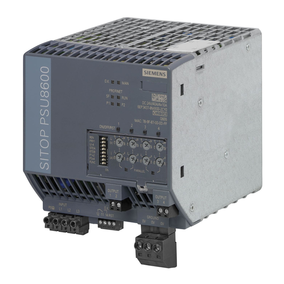
SITOP PSU8600
Manual
SITOP PSU8600 DC 24 V/20 A
6EP3436-8SB00-2AY0
SITOP PSU8600 DC 24 V/40 A
6EP3437-8SB00-2AY0
SITOP CNX8600 4 x 5 A
6EP4436-8XB00-0CY0
SITOP CNX8600 4 x 10 A
6EP4437-8XB00-0CY0
SITOP CNX8600 8 x 2.5 A
6EP4436-8XB00-0DY0
SITOP BUF8600 100 ms/40 A
6EP4297-8HB00-0XY0
SITOP BUF8600 300 ms/40 A
6EP4297-8HB10-0XY0
SITOP BUF8600 4 s/40 A
6EP4293-8HB00-0XY0
SITOP BUF8600 10 s/40 A
6EP4295-8HB00-0XY0
SITOP UPS8600 40 A
6EP4197-8AB00-0XY0
SITOP BAT8600 LiFePO4 264 Wh
6EP4143-8JB00-0XY0
SITOP BAT8600 Pb
6EP4145-8GB00-0XY0
09.2018
A5E36758446-5-76
Overview
Safety and security
Description, device design,
dimension drawing
Operator control at the
device
Mounting and maintenance
Mounting position, mounting
clearances
Installation
Engineering and remote
access
Troubleshooting
Technical data
Safety, approvals, EMC
Ambient conditions
Applications
Environment
Service & Support
1
2
3
4
5
6
7
8
9
10
11
12
13
14
Advertisement
Table of Contents

Related Manuals for Siemens SITOP PSU8600


Summary of Contents for Siemens SITOP PSU8600
- Page 1 Mounting and maintenance SITOP PSU8600 Mounting position, mounting clearances Manual Installation Engineering and remote access SITOP PSU8600 DC 24 V/20 A Troubleshooting 6EP3436-8SB00-2AY0 SITOP PSU8600 DC 24 V/40 A 6EP3437-8SB00-2AY0 Technical data SITOP CNX8600 4 x 5 A 6EP4436-8XB00-0CY0 SITOP CNX8600 4 x 10 A...
- Page 2 Note the following: WARNING Siemens products may only be used for the applications described in the catalog and in the relevant technical documentation. If products and components from other manufacturers are used, these must be recommended or approved by Siemens. Proper transport, storage, installation, assembly, commissioning, operation and maintenance are required to ensure that the products operate safely and without any problems.
-
Page 3: Overview
Overview The SITOP PSU8600 power supply system is the high-performance, regulated technology power supply system for automated plants and machines. The key benefits of the product include: ● Wide-range input, which allows them to be connected to almost all 3-phase line supplies around the world ●... - Page 4 ● Longer power failures can be buffered using the SITOP UPS8600 UPS module and SITOP BAT8600 battery module (either using lead acid or lithium iron phosphate batteries) Ordering data Basic units and supplementary modules: Power supply system SITOP PSU8600 Type Article number Basic unit SITOP PSU8600 3AC 400 - 500 V input...
- Page 5 Overview Validity This manual provides information on the following products: ● Basic unit SITOP PSU8600 24 V DC/20 A PN Article number: 6EP3436-8SB00-2AY0 Product state: 2 Firmware version: V1.4 Functional expansion with respect to the previous version (PS: 2, FW: V1.3): –...
- Page 6 Article number: 6EP4145-8GB00-0XY0 Product state: 1 Firmware version: V1.4 – Initial version ● SITOP BAT8600 LiFePO4 264 Wh battery module Article number: 6EP4143-8JB00-0XY0 Product state: 1 Firmware version: V1.4 – Initial version Power supply system SITOP PSU8600 Manual, 09.2018, A5E36758446-5-76...
-
Page 7: Table Of Contents
Security information ........................ 14 Safety instructions for explosive environments/zones ............15 1.3.1 Safety note - ATEX Directive HB PSU8600................15 1.3.2 Basic SITOP PSU8600 device ....................15 1.3.3 Expansion modules SITOP CNX8600 ..................15 1.3.4 SITOP UPS8600 UPS module ....................15 1.3.5... - Page 8 4.6.3 Response after removing an individual component ............. 134 Replacing batteries in a battery module ................136 4.7.1 Replacing the batteries ......................136 4.7.2 Service life and storing the batteries ..................139 Power supply system SITOP PSU8600 Manual, 09.2018, A5E36758446-5-76...
- Page 9 Other mounting positions ...................... 145 5.2.1 Basic device SITOP PSU8600 20 A ..................145 5.2.2 Basic device SITOP PSU8600 20 A and supplementary modules ........147 5.2.3 Basic device SITOP PSU8600 40 A ..................149 5.2.4 Basic device SITOP PSU8600 40 A and supplementary modules: ........151 Installation ............................
- Page 10 Preconditions ........................304 7.8.3 Activating the OPC UA server via the SITOP PSU8600 web server ........305 7.8.4 Establishing a connection to the OPC UA server of the SITOP PSU8600 ......306 7.8.5 Working with the OPC UA client ..................310 7.8.5.1 Displaying SITOP PSU8600 parameters ................
- Page 11 Table of contents 7.8.6 Parameters of the SITOP PSU8600 in the OPC UA client ........... 314 7.8.6.1 ActualBufferState ........................315 7.8.6.2 ActualState ..........................315 7.8.6.3 ActualUpdateState ........................ 316 7.8.6.4 Alarm ............................. 316 7.8.6.5 Buffering ..........................321 7.8.6.6 General ..........................321 7.8.6.7...
- Page 12 EMC ............................. 408 Ambient conditions ..........................411 Applications ............................413 12.1 Parallel connection to increase power rating ............... 413 12.2 Parallel connection for redundancy ..................414 Environment ............................417 Service & Support ..........................419 Power supply system SITOP PSU8600 Manual, 09.2018, A5E36758446-5-76...
-
Page 13: Safety And Security
Before installation or maintenance work can begin, the system's main switch must be switched off and measures taken to prevent it being switched on again. If this instruction is not observed, touching live parts can result in death or serious injury. Power supply system SITOP PSU8600 Manual, 09.2018, A5E36758446-5-76... -
Page 14: Security Information
In order to protect plants, systems, machines and networks against cyber threats, it is necessary to implement – and continuously maintain – a holistic, state-of-the-art industrial security concept. Siemens’ products and solutions only form one element of such a concept. Customer is responsible to prevent unauthorized access to its plants, systems, machines and networks. -
Page 15: Safety Instructions For Explosive Environments/Zones
Safety instructions for explosive environments/zones 1.3.1 Safety note - ATEX Directive HB PSU8600 All devices of the SITOP PSU8600 family – with the exception of SITOP BAT8600 LiFePO4 6EP4143-8JB00-0XY0 – comply with ATEX Directive 2014/34/EU; EN 60079-0; EN 60079-15. 1.3.2... -
Page 16: Sitop Bat8600 Battery Modules
ONLY REMOVE / INSERT THE FUSE OR REPLACE BATTERIES IN NON-EXPLOSIVE ENVIRONMENTS! 1.3.5.1 Safety instructions for warning BAT8600 WARNING In hazardous zones, it is not permissible that BAT8600 battery modules are connected in parallel! Power supply system SITOP PSU8600 Manual, 09.2018, A5E36758446-5-76... -
Page 17: Description, Device Design, Dimension Drawing
Description, device design, dimension drawing Description of the basic devices The basic units SITOP PSU8600 are primary-clocked power supplies for connection to 3- phase AC line supplies. An electronically controlled DC voltage that can be set via a potentiometer is available at the output of the devices. The device output is isolated, no-load and short-circuit proof and has an electronic overload trip - or alternatively overload current limiting (constant current), which can be set using an additional potentiometer. - Page 18 Socket at the upper side of the device for the plug connection to optional supplementary modules ⑪ Buttons of the outputs with LED display "ON/OFF/RST" ⑫ Voltage potentiometer U (V) ⑬ Current potentiometer I (A) ⑭ DIP switch, special functions from Power supply system SITOP PSU8600 Manual, 09.2018, A5E36758446-5-76...
-
Page 19: Description Of The Expansion Modules
4 × 10 A expansion module 10 A 6EP4437-8XB00-0CY0 8 × 2.5 A expansion module 2.5 A 6EP4436-8XB00-0DY0 Note 6EP4436-8XB00-0DY0 expansion module In the MANUAL mode, the voltage and current potentiometers set the values for 2 outputs. Power supply system SITOP PSU8600 Manual, 09.2018, A5E36758446-5-76... - Page 20 GROUND terminal for optional ground connection to the basic unit ⑤ "O.K LED." ⑥ DIN rail slider ⑦ Convection ⑧ Clearance above/below ⑨ Buttons of the outputs with LED display "ON/OFF/RST" ⑩ Voltage potentiometer U (V) ⑪ Current potentiometer I (A) Power supply system SITOP PSU8600 Manual, 09.2018, A5E36758446-5-76...
-
Page 21: Description Of The Buffer Modules
Article number input voltage of 400 V Buffer module 100 ms at 40 A 20 s 6EP4297-8HB00-0XY0 100 ms/40 A Buffer module 300 ms at 40 A 60 s 6EP4297-8HB10-0XY0 300 ms/40 A Power supply system SITOP PSU8600 Manual, 09.2018, A5E36758446-5-76... - Page 22 When the buffer module with electrolytic capacitors is completely charged (LED "O.K." lights green), power failures of 100 ms or 300 ms can be buffered with a load current of 40 A. The buffer time is appropriately increased for lower load currents. Power supply system SITOP PSU8600 Manual, 09.2018, A5E36758446-5-76...
- Page 23 When the buffer module with double-layer capacitors is completely charged (LED "O.K." lights green), power failures of 4 s or 10 s can be buffered with a load current of 40 A. The buffer time is appropriately increased for lower load currents. Power supply system SITOP PSU8600 Manual, 09.2018, A5E36758446-5-76...
- Page 24 However, the selection and parameterization is only possible via the configuration (STEP 7, OPC UA Server, web server). You can find more information in Chapter "Engineering and remote access (Page 169)" Power supply system SITOP PSU8600 Manual, 09.2018, A5E36758446-5-76...
- Page 25 3 s up to a maximum of 8 s can be buffered with a load current of 40 A. The LONGLIFE mode can only be selected via the configuration (STEP 7, OPC UA server, web server). You can find more information in Chapter "Engineering and remote access (Page 169)" Power supply system SITOP PSU8600 Manual, 09.2018, A5E36758446-5-76...
-
Page 26: Description Of The Ups Module
When configuring, the UPS module should be considered as an output of the power supply system; this means that the charging power of the UPS module should be subtracted from the system power available for the outputs. Power supply system SITOP PSU8600 Manual, 09.2018, A5E36758446-5-76... - Page 27 ⑥ Control contact "START" ⑦ "READY" signaling contact ⑧ "BUF" signaling contact ⑨ "OK" signaling contact ⑩ "OK", "BAT" LEDs ⑪ DIP switch ⑫ DIN rail slider ⑬ Convection ⑭ Clearance above/below Power supply system SITOP PSU8600 Manual, 09.2018, A5E36758446-5-76...
-
Page 28: Description Of The Battery Modules
380 Wh typ. 10 min 6EP4145-8GB00-0XY0 (system power 960 W) typ. 25 min (system power 480 W) Valid for a new, fully charged battery module at an ambient temperature of 25 °C Power supply system SITOP PSU8600 Manual, 09.2018, A5E36758446-5-76... - Page 29 2.5 Description of the battery modules ① DC power terminals ② Communication terminals ③ Fuse ④ "OK" LED ⑤ Reset button ⑥ Screw for the housing cover ⑦ Reserve fuse ⑧ Housing cover ⑨ Clearance above Power supply system SITOP PSU8600 Manual, 09.2018, A5E36758446-5-76...
- Page 30 Description, device design, dimension drawing 2.5 Description of the battery modules Buffer times Figure 2-2 Typical buffer times for a new, completely charged BAT8600 Pb battery module at an ambient temperature of 25 °C Power supply system SITOP PSU8600 Manual, 09.2018, A5E36758446-5-76...
- Page 31 (see Chapter "Specifying the buffer time limiting (Page 107)"). Additional information about the battery modules is also provided in Chapter "Service life and storing the batteries (Page 139)". Power supply system SITOP PSU8600 Manual, 09.2018, A5E36758446-5-76...
-
Page 32: Connections And Terminal Designations
See the diagram in Section "Description of the basic devices (Page 17)". Terminal data 6EP3436-8SB00-2AY0: *1) Do not subject the end stop to high loads *2) Derating 18 A/60 °C or 20 A/50 °C Power supply system SITOP PSU8600 Manual, 09.2018, A5E36758446-5-76... - Page 33 Commercially available RJ45 plug connectors can be used to connect to Ethernet/PROFINET. However, when withdrawing the cable, a suitable tool must be used (e.g. a small slotted screwdriver) in order to release the RJ45 plug connector latch. Power supply system SITOP PSU8600 Manual, 09.2018, A5E36758446-5-76...
-
Page 34: Expansion Modules
Plug-in terminal with three screw connections Ground terminal GROUND See the diagram in Section "Description of the expansion modules (Page 19)". Terminal data 6EP4436-8XB00-0CY0, 6EP4437-8XB00-0CY0, 6EP4436-8XB00-0DY0: *1) Do not subject the end stop to high loads Power supply system SITOP PSU8600 Manual, 09.2018, A5E36758446-5-76... -
Page 35: Buffer Modules
Signaling contact Sufficient buffer readiness "READY" 13, 14 ⑥ Signaling contact Buffer mode "BUF" 23, 24 See the diagram in Section "Description of the buffer modules (Page 21)". Terminal data 6EP4293-8HB00-0XY0, 6EP4295-8HB00-0XY0: Power supply system SITOP PSU8600 Manual, 09.2018, A5E36758446-5-76... -
Page 36: Ups Module
Common plug-in terminal each with a screw connection ⑧ Signaling contact "BUF" 23, 24 ⑨ "OK" signaling contact 33, 34 See the diagram in Section "Description of the UPS module (Page 26)". Power supply system SITOP PSU8600 Manual, 09.2018, A5E36758446-5-76... - Page 37 Wiring between the UPS module UPS8600 and battery module BAT8600 Terminal data When wiring several BAT8600 battery modules – or battery modules from third-party suppliers – see Chapter "Connecting battery modules to the UPS module (Page 163)". Power supply system SITOP PSU8600 Manual, 09.2018, A5E36758446-5-76...
-
Page 38: Battery Modules
Power terminals "-" and "+" ② Plug-in terminal each with a screw connection Communication terminals "COM2", "COM1" See the diagram in Section "Description of the battery modules (Page 28)". Terminal data 6EP4143-8JB00-0XY0, 6EP4145-8GB00-0XY0 Power supply system SITOP PSU8600 Manual, 09.2018, A5E36758446-5-76... -
Page 39: Operator Controls
Description, device design, dimension drawing 2.7 Operator controls Operator controls 2.7.1 Basic units There are two main operating areas at the SITOP PSU8600 basic unit. ① ② ③ ● LED buttons and potentiometers ( The potentiometers are used to set the output voltage and response threshold value of the output current. - Page 40 When required, this plastic cover can be sealed to prevent the operating elements being actuated by unauthorized personnel. To seal, the sealing wire is routed through an opening in the plastic cover and housing, as shown in the following diagram. Power supply system SITOP PSU8600 Manual, 09.2018, A5E36758446-5-76...
-
Page 41: Expansion Modules
Switches-on and switches-off an output, resets an output after an elec- "ON/OFF/RST" tronic shutdown; see Chapter "Switching an output on and off (Page 84)" and "Overload shutdown and carrying out a reset (Page 85)". Power supply system SITOP PSU8600 Manual, 09.2018, A5E36758446-5-76... - Page 42 When required, this plastic cover can be sealed to prevent the operating elements being actuated by unauthorized personnel. To seal, the sealing wire is routed through an opening in the plastic cover and housing, as shown in the following diagram. Power supply system SITOP PSU8600 Manual, 09.2018, A5E36758446-5-76...
-
Page 43: Ups Module
DIP switches being actuated by unauthorized personnel. To seal, the sealing wire is routed through an opening in the plastic cover and housing. Power supply system SITOP PSU8600 Manual, 09.2018, A5E36758446-5-76... -
Page 44: Battery Modules
Designation Function Labeling ⑤ BAT LIFETIME Resets the counter for the battery service life; see Chapter "Replacing the RESET batteries (Page 136)". Power supply system SITOP PSU8600 Manual, 09.2018, A5E36758446-5-76... -
Page 45: Display Elements
Signal type Signaling ① O.K. Device status ② Mode ③ Group error ④ RUN/STOP ⑤ P1, P2 Receive/transmit, port 1 and port 2 ⑥ ON/OFF/RST LED buttons Operating mode of the output Power supply system SITOP PSU8600 Manual, 09.2018, A5E36758446-5-76... - Page 46 MANUAL mode, i.e. setting directly at the device Flashing green (1/1) MANUAL mode; the mode has been changed in operation, settings directly at the device do not necessarily correspond to the active reference parameters. Power supply system SITOP PSU8600 Manual, 09.2018, A5E36758446-5-76...
- Page 47 Signaling Device is OFF or is not connected with the IO controller Green Device is connected with IO controller, no activity. Green/orange alternately Device connected with the IO controller, send/receive data (RX/TX). Power supply system SITOP PSU8600 Manual, 09.2018, A5E36758446-5-76...
- Page 48 Flashing red (1/1) Output switched off via control command (REMOTE mode) Yellow Output manually switched off using the button at the device Power supply system SITOP PSU8600 Manual, 09.2018, A5E36758446-5-76...
-
Page 49: Expansion Modules
Description, device design, dimension drawing 2.8 Display elements 2.8.2 Expansion modules Labeling Signal type Signaling ① O.K. Device status ② ON/OFF/RST LED buttons Operating state of the particular output Power supply system SITOP PSU8600 Manual, 09.2018, A5E36758446-5-76... - Page 50 (power OFF/ON) Device shut down due to firmware update of another system component • Incorrect hardware configuration (REMOTE mode) • Yellow Power failure, buffer mode active Alternating, green/red Firmware being updated. (0.25/0.25) Power supply system SITOP PSU8600 Manual, 09.2018, A5E36758446-5-76...
- Page 51 Flashing red (1/1) Output switched off via control command (REMOTE mode) Yellow Output manually switched off using the button at the device Power supply system SITOP PSU8600 Manual, 09.2018, A5E36758446-5-76...
-
Page 52: Buffer Modules
Description, device design, dimension drawing 2.8 Display elements 2.8.3 Buffer modules Labeling Signal type Signaling ① O.K. Device status Power supply system SITOP PSU8600 Manual, 09.2018, A5E36758446-5-76... - Page 53 Charge is still available after power supply voltage OFF • Device shut down due to firmware update of another system component • Incorrect hardware configuration (REMOTE mode) • Yellow Power failure, buffer mode active Alternating, green/red Firmware being updated (0.25/0.25) Power supply system SITOP PSU8600 Manual, 09.2018, A5E36758446-5-76...
-
Page 54: Ups Module
Description, device design, dimension drawing 2.8 Display elements 2.8.4 UPS module Labeling Signal type Signaling ① O.K. Device status ② BAT. State of the connected battery modules Power supply system SITOP PSU8600 Manual, 09.2018, A5E36758446-5-76... - Page 55 Module ready for automatic ERROR OFF shutdown by switching off the sup- • ply voltage and switching it on again (power OFF/ON) Incorrect hardware configuration or incorrect battery type (remote operating • mode) Alternating, green/red Firmware being updated (0.25/0.25) Power supply system SITOP PSU8600 Manual, 09.2018, A5E36758446-5-76...
- Page 56 While replacing the battery, request to immediately reset the lifetime counter • using the reset button Cyclic battery test is negative, batteries must be replaced Buffer mode not possible Alternating, green/red Battery replacement confirmed (0.25/0.25 A for 5 s) Power supply system SITOP PSU8600 Manual, 09.2018, A5E36758446-5-76...
-
Page 57: Battery Modules
Power connections interrupted or fuse defective/ruptured, buffer mode not • possible While replacing the battery, request to immediately reset the lifetime counter • using the reset button Alternating, green/red Battery replacement confirmed (0.25/0.25 A for 5 s) Power supply system SITOP PSU8600 Manual, 09.2018, A5E36758446-5-76... -
Page 58: Signaling Contacts/Control Contacts
Basic unit has limited power output and expansion mod- • ule shut down due to system overload Output switched off due to overtemperature • Communication error between the basic unit and sup- • plementary module Expansion module failure • Power supply system SITOP PSU8600 Manual, 09.2018, A5E36758446-5-76... -
Page 59: Buffer Modules
The signal "Sufficient buffer readiness" refers exclusively to the SITOP BUF8600 buffer modules with double-layer capacitors. Power supply system SITOP PSU8600 Manual, 09.2018, A5E36758446-5-76... - Page 60 SITOP BUF8600 buffer modules with electrolytic capacitors are not taken into account. Signaling contact Explanation 23-24 open Normal operation. (quiescent state) Buffer module is charged (if required). 23-24 closed Power failure, buffer mode System is buffered via the buffer component(s). Power supply system SITOP PSU8600 Manual, 09.2018, A5E36758446-5-76...
-
Page 61: Ups Module
) - and signals that the buffer module is charged to x % (factory setting: 85 %) and is therefore ready for buffering. The threshold value can be freely parameterized via the Industrial Ethernet/PROFINET interface. Power supply system SITOP PSU8600 Manual, 09.2018, A5E36758446-5-76... - Page 62 Battery service life limit reached • Battery module has been deeply discharged • Service the connected BAT8600 (replace the batteries) • Firmware update • 33-34 closed Normal operation (no fault in the connected battery circuit) Power supply system SITOP PSU8600 Manual, 09.2018, A5E36758446-5-76...
-
Page 63: Block Diagrams
Description, device design, dimension drawing 2.10 Block diagrams 2.10 Block diagrams SITOP PSU8600 basic unit SITOP CNX8600 expansion modules (4 outputs) Power supply system SITOP PSU8600 Manual, 09.2018, A5E36758446-5-76... - Page 64 Description, device design, dimension drawing 2.10 Block diagrams SITOP CNX8600 expansion modules (8 outputs) SITOP BUF8600 100 ms/40 A and SITOP BUF8600 300 ms/40 A buffer modules Power supply system SITOP PSU8600 Manual, 09.2018, A5E36758446-5-76...
- Page 65 Description, device design, dimension drawing 2.10 Block diagrams SITOP BUF8600 4 s/40 A and SITOP BUF8600 10 s/40 A buffer modules SITOP UPS8600 UPS module SITOP BAT8600 battery modules Power supply system SITOP PSU8600 Manual, 09.2018, A5E36758446-5-76...
-
Page 66: Dimensions And Weights
Description, device design, dimension drawing 2.11 Dimensions and weights 2.11 Dimensions and weights SITOP PSU8600 basic units Figure 2-4 Dimension drawing 6EP3436-8SB00-2AY0 front and left views Power supply system SITOP PSU8600 Manual, 09.2018, A5E36758446-5-76... - Page 67 Description, device design, dimension drawing 2.11 Dimensions and weights Figure 2-5 Dimension drawing 6EP3436-8SB00-2AY0 view from below Figure 2-6 Dimension drawing 6EP3437-8SB00-2AY0 front and left views Power supply system SITOP PSU8600 Manual, 09.2018, A5E36758446-5-76...
- Page 68 Description, device design, dimension drawing 2.11 Dimensions and weights Figure 2-7 Dimension drawing 6EP3437-8SB00-2AY0 view from below Power supply system SITOP PSU8600 Manual, 09.2018, A5E36758446-5-76...
- Page 69 Description, device design, dimension drawing 2.11 Dimensions and weights Expansion modules SITOP CNX8600 Figure 2-8 Dimension drawing for 6EP4436-8XB00-0CY0 and 6EP4437-8XB00-0CY0 Power supply system SITOP PSU8600 Manual, 09.2018, A5E36758446-5-76...
- Page 70 Description, device design, dimension drawing 2.11 Dimensions and weights Figure 2-9 Dimension drawing for 6EP4436-8XB00-0DY0 Power supply system SITOP PSU8600 Manual, 09.2018, A5E36758446-5-76...
- Page 71 Description, device design, dimension drawing 2.11 Dimensions and weights Buffer modules SITOP BUF8600 Figure 2-10 Dimension drawing 6EP4297-8HB00-0XY0 Power supply system SITOP PSU8600 Manual, 09.2018, A5E36758446-5-76...
- Page 72 Description, device design, dimension drawing 2.11 Dimensions and weights Figure 2-11 Dimension drawing 6EP4297-8HB10-0XY0 Power supply system SITOP PSU8600 Manual, 09.2018, A5E36758446-5-76...
- Page 73 Description, device design, dimension drawing 2.11 Dimensions and weights Figure 2-12 Dimension drawing 6EP4293-8HB00-0XY0 Power supply system SITOP PSU8600 Manual, 09.2018, A5E36758446-5-76...
- Page 74 Description, device design, dimension drawing 2.11 Dimensions and weights Figure 2-13 Dimension drawing 6EP4295-8HB00-0XY0 Power supply system SITOP PSU8600 Manual, 09.2018, A5E36758446-5-76...
- Page 75 Description, device design, dimension drawing 2.11 Dimensions and weights SITOP UPS8600 UPS module Figure 2-14 Dimension drawing 6EP4197-8AB00-0XY0 Power supply system SITOP PSU8600 Manual, 09.2018, A5E36758446-5-76...
- Page 76 Description, device design, dimension drawing 2.11 Dimensions and weights SITOP BAT8600 battery modules Figure 2-15 Dimension drawing 6EP4145-8GB00-0XY0 and 6EP4143-8JB00-0XY0 Power supply system SITOP PSU8600 Manual, 09.2018, A5E36758446-5-76...
- Page 77 Dimensions 60 × 125 × 150 322 × 187.3 × 110.2 322 × 187.3 110.2 (W × H × D) in mm Weight Approx. 0.9 kg Approx. 6.5 kg Approx. 13 kg Power supply system SITOP PSU8600 Manual, 09.2018, A5E36758446-5-76...
- Page 78 Description, device design, dimension drawing 2.11 Dimensions and weights Power supply system SITOP PSU8600 Manual, 09.2018, A5E36758446-5-76...
-
Page 79: Operator Control At The Device
REMOTE operating modes (Page 88)". These operator controls are deactivated in the REMOTE mode. ③ The output can be switched-on/switched-off and reset in any mode using button Operating the expansion modules All operator controls are located at the front. Power supply system SITOP PSU8600 Manual, 09.2018, A5E36758446-5-76... - Page 80 MANUAL mode (see Chapter "MANUAL and REMOTE operating modes (Page 88)"). These operator controls are deactivated in the REMOTE mode. ③ The outputs can be switched-on/switched-off and reset in any mode using button Power supply system SITOP PSU8600 Manual, 09.2018, A5E36758446-5-76...
- Page 81 Settings at the UPS module using DIP switches are only accepted in the MANUAL mode, see Chapter "MANUAL and REMOTE operating modes (Page 88)". These operator controls are deactivated in the REMOTE mode. Power supply system SITOP PSU8600 Manual, 09.2018, A5E36758446-5-76...
-
Page 82: Setting The Output Voltage And Response Threshold Value Of The Output Current
6EP4436-8XB00-0DY0 expansion module In the MANUAL mode, the values set by the voltage and current potentiometers are valid for 2 outputs. ② Voltage potentiometer for the output ③ Current potentiometer for the output Power supply system SITOP PSU8600 Manual, 09.2018, A5E36758446-5-76... -
Page 83: Setting The Output Voltage
Value range at the basic units depending on the type: 2 to 20 A or 4 to 40 A. Value range at the expansion module depending on the type: 0.5 up to 2.5 A, 0.5 up to 5 A or 0.5 up to 10 A. Factory setting: relevant maximum value. Power supply system SITOP PSU8600 Manual, 09.2018, A5E36758446-5-76... -
Page 84: Switching An Output On And Off
The LED in the button is lit yellow when the output is manually switched off. ● You can switch on the output by pressing the button. The LED is lit green (output is switched on). Power supply system SITOP PSU8600 Manual, 09.2018, A5E36758446-5-76... -
Page 85: Overload Shutdown And Carrying Out A Reset
Using a reset, the output that has been automatically switched off can be switched-on again after a wait time of 5 seconds. If the output is ready for the reset, then LED "ON/OFF/RST" of the output flashes red. Power supply system SITOP PSU8600 Manual, 09.2018, A5E36758446-5-76... - Page 86 If, after a reset, the cause of the overload is still present, then the output is again automatically switched off according to the shutdown characteristics. To prevent a new shutdown, before carrying out a RESET, remove the cause of the overload. Power supply system SITOP PSU8600 Manual, 09.2018, A5E36758446-5-76...
- Page 87 (function only available when using a CNX8600 expansion module). Note The rising edge of the reset signal is evaluated. This means for an additional reset signal, the voltage level must first drop down to below 13 V. Power supply system SITOP PSU8600 Manual, 09.2018, A5E36758446-5-76...
-
Page 88: Manual And Remote Operating Modes
④ The switchover is made at the DIP switch with the designation "REN" (see operator controls). When delivered, DIP switch "REN" is in position "OFF" (MANUAL mode). Power supply system SITOP PSU8600 Manual, 09.2018, A5E36758446-5-76... - Page 89 DIP switches only become active after they have been actuated. Activating the REMOTE operating mode With the power supply system shut down, bring DIP switch "REN" into position "ON" (right), to activate the REMOTE operating mode. Power supply system SITOP PSU8600 Manual, 09.2018, A5E36758446-5-76...
- Page 90 • Only switch over the operating mode when the power supply system is shut down. • Before switching over in operation, ensure that the remote configuration corresponds to the actual device settings. Power supply system SITOP PSU8600 Manual, 09.2018, A5E36758446-5-76...
-
Page 91: Prioritization When The Line Supply Fails
⑤ The switchover is made at DIP switch with the designation "PRY 1" (see operator controls). When delivered, the DIP switch "PRY 1" is in position "OFF" (prioritization deactivated). Power supply system SITOP PSU8600 Manual, 09.2018, A5E36758446-5-76... - Page 92 Outputs 2 ... n, which are switched off when the power fails as output 1 has priority, are automatically switched-on again when the line supply returns. • Lock-out the connected loads so they cannot inadvertently start. Power supply system SITOP PSU8600 Manual, 09.2018, A5E36758446-5-76...
-
Page 93: Electronic Shutdown And Constant Current Operating Modes
⑥ The switchover is made at DIP switch with the designation "UI-1" (see operator controls). When delivered, the DIP switch "UI-1" is in position "OFF" (ELECTRONIC SHUTDOWN operating mode). Power supply system SITOP PSU8600 Manual, 09.2018, A5E36758446-5-76... - Page 94 With the power supply system shut down, bring DIP switch "UI-1" into position "OFF" (left), to activate the ELECTRONIC SHUTDOWN mode. Constant current With the power supply system shut down, bring DIP switch "UI-1" into position "ON" (right), to activate the CONSTANT CURRENT mode. Power supply system SITOP PSU8600 Manual, 09.2018, A5E36758446-5-76...
-
Page 95: Setting The On Delay
3.7 Setting the on delay Setting the on delay In order to reduce the load on the SITOP PSU8600 power supply system as a result of simultaneous switch-on current peaks of the loads at the output of the basic unit and at the outputs of the expansion modules, a switch on delay between the outputs can be selected when switching on. - Page 96 "STDB" into position "ON" (right) in order to set the on delay to 100 ms. STDA STDB Load-optimized on delay With the power supply system shut down, bring both DIP switches "STDA" and "STDB" into position "ON" (right) to activate load-optimized on delay. STDA STDB Power supply system SITOP PSU8600 Manual, 09.2018, A5E36758446-5-76...
-
Page 97: Setting The Output Characteristic
3.8 Setting the output characteristic Setting the output characteristic For the standard output characteristic of the basic SITOP PSU8600 device, the output voltage is controlled to obtain a constant value independent of the output current. If the "soft" output characteristic is selected, then the output voltage slightly decreases as the output current increases. -
Page 98: Activate The Web Server For The Manual Operating Mode On The Module
Activate the web server for the MANUAL operating mode on the module The basic SITOP PSU8600 device has an integrated web server. This facilitates remote monitoring and diagnostics, for example to interrogate actual currents and messages/signals. Further, the actual module configuration can be viewed, if necessary changed and externally saved to a file and archived. - Page 99 Note No write access when the connection is active If the SITOP PSU8600 has an active connection to a control system (relation application), then the parameters can only be read-accessed. It is still possible to update the firmware - and save and delete the alarm list. If there is no active connection, then parameters can also be write accessed via the web server.
-
Page 100: Activating And Deactivating Buffer Operation
When the power fails, the power supply system is not buffered using the buffer components. Buffer mode is immediately exited if the connection between terminals "X1" and "X2" is opened during buffering. Power supply system SITOP PSU8600 Manual, 09.2018, A5E36758446-5-76... - Page 101 This also applies to buffer modules with electrolytic capacitors, without control contact! Note The external circuit must meet the requirements relating to SELV circuits according to EN 60950-1. Power supply system SITOP PSU8600 Manual, 09.2018, A5E36758446-5-76...
-
Page 102: Starting The Power Supply System With Energy From The Battery Module (Island Operation)
Note The external circuit must meet the requirements relating to SELV circuits according to EN 60950-1. See also Chapter "When starting from the battery, only output 1 is activated (Page 106)". Power supply system SITOP PSU8600 Manual, 09.2018, A5E36758446-5-76... -
Page 103: Setting The Charging Power Of The Ups Module
120 W (default setting). Bring DIP switch "CHRG LOW" into the "ON" position (right) to set the charging power to 60 W (default setting). Note The setting becomes immediately active in the MANUAL mode. Power supply system SITOP PSU8600 Manual, 09.2018, A5E36758446-5-76... - Page 104 Carefully note that the battery module temperature can increase due to charging and buffer operations, even at lower ambient temperatures. This can result in the charge power been reduced or shut down as a result of the temperature monitoring inside the battery module. Power supply system SITOP PSU8600 Manual, 09.2018, A5E36758446-5-76...
-
Page 105: Selecting The Preferred Charging Mode For A System Start
Set DIP switch "PRE CHRG" at all UPS modules to the "OFF" position (left) to activate the outputs immediately after the system has run up. Power supply system SITOP PSU8600 Manual, 09.2018, A5E36758446-5-76... -
Page 106: When Starting From The Battery, Only Output 1 Is Activated
Set DIP SWITCH "START PRY1" to the "OFF" position (left) so that after being started from the battery module, all outputs are activated. See also Chapter "Starting the power supply system with energy from the battery module (island operation) (Page 102)". Power supply system SITOP PSU8600 Manual, 09.2018, A5E36758446-5-76... -
Page 107: Specifying The Buffer Time Limiting
Note The set buffer time limiting only refers to the particular UPS module, and does not include additional buffer components in the system. Power supply system SITOP PSU8600 Manual, 09.2018, A5E36758446-5-76... -
Page 108: Monitoring Functions
3.16.1 Overtemperature monitoring functions In the SITOP PSU8600 basic unit, in the SITOP CNX8600 expansion modules and in the UPS8600, overtemperature monitoring functions are integrated, which shut down the relevant components when the temperature inside the component reaches an inadmissibly high level. - Page 109 2. Switch-off the power supply for the SITOP PSU8600 for at least 10 seconds. 3. Switch on the supply voltage again. The overall system and the outputs have the same operating state before the shutdown due to high temperature.
- Page 110 At ambient temperatures of the BAT8600 Pb battery modules between 40 °C and 50 °C, the charge power is automatically reduced down to 60 W if only one battery module is connected to the UPS module. Power supply system SITOP PSU8600 Manual, 09.2018, A5E36758446-5-76...
-
Page 111: Phase Failure Monitoring
The following signals indicate a shutdown due to phase imbalance: ① ● Red LED "O.K." at the basic unit and at the supplementary modules ② ● LEDs "ON/OFF/RST" of all outputs go dark ● Signaling contact at the basic unit Power supply system SITOP PSU8600 Manual, 09.2018, A5E36758446-5-76... - Page 112 LED "ON/OFF/RST" Reset of a shutdown as a result of a phase failure 1. Shut down the supply voltage of the SITOP PSU8600 for at least 10 seconds, and remove the cause of the unbalanced line supply. 2. Switch on the supply voltage again.
-
Page 113: System Overload Monitoring
● red LED "O.K." of the expansion modules ② ● Red LEDs "ON/OFF/RST" of the outputs of the expansion modules ● The signaling contact at the basic unit ① LED "O.K." ② LED "ON/OFF/RST" Power supply system SITOP PSU8600 Manual, 09.2018, A5E36758446-5-76... -
Page 114: Protection Functions For Connections At The Ups Module
An appropriate signal is generated if wire breakage is detected. Buffer operation can continue if a broken wire is detected in one of the data cables. Power supply system SITOP PSU8600 Manual, 09.2018, A5E36758446-5-76... -
Page 115: Restore Factory Settings
Proceed as follows to reset the SITOP PSU8600 factory settings: 1. While the SITOP PSU8600 is operational, at the basic unit, press the button for output 1 Keep the button pressed for approximately 5 s until the "MAN" LED at the device flashes green. - Page 116 Operator control at the device 3.17 Restore factory settings Power supply system SITOP PSU8600 Manual, 09.2018, A5E36758446-5-76...
-
Page 117: Mounting And Maintenance
Use in hazardous zones When the SITOP PSU8600 power supply system is installed in a hazardous zone (Ex II 3G Ex nA nC IIC T4 Gc, Ex II 3G Ex nA IIC T4 Gc, Ex II 3G Ex nA IIC T5 Gc), then it must be accommodated in a distribution box with IP54 degree of protection or higher. -
Page 118: Rail Mounting
1. Position the device with the mounting rail guide at the upper edge of the standard mounting rail and press down to lock it into place. 2. If it is difficult to snap it into place, simultaneously press the slider using a screwdriver. Power supply system SITOP PSU8600 Manual, 09.2018, A5E36758446-5-76... - Page 119 6. Connect the supplementary module to the basic unit using the plug connector: – Close the plug connector so that it engages in the appropriate socket at the basic device. ① – Ensure that latch snaps into place. Power supply system SITOP PSU8600 Manual, 09.2018, A5E36758446-5-76...
- Page 120 If the unit is to be used in a potentially explosive environment (II 3G nA IIC T4 Gc), it must be installed in a distributor box with degree of protection IP54 or higher. This distribution box must comply with the requirements of EN 60079-15 and must require a tool for opening. Power supply system SITOP PSU8600 Manual, 09.2018, A5E36758446-5-76...
- Page 121 When mounting, ensure that there is a minimum 20 mm clearance above the unit. Ensure that the units are accessible so that the batteries can be replaced at a later date. 2. Connect the battery modules to the UPS module. Power supply system SITOP PSU8600 Manual, 09.2018, A5E36758446-5-76...
-
Page 122: Permissible Hardware Configurations
960 W - and the maximum output current is 20 A or 40 A. Expansion modules, PSU8600 power supply system Type Article number SITOP CNX8600 4 x 5 A 6EP4436-8XB00-0CY0 SITOP CNX8600 4 x 10 A 6EP4437-8XB00-0CY0 SITOP CNX8600 8 x 2.5 A 6EP4436-8XB00-0DY0 Power supply system SITOP PSU8600 Manual, 09.2018, A5E36758446-5-76... - Page 123 After the buffer module has been discharged, then the UPS module takes over the buffering. In the buffer mode, the UPS module does not charge the buffer module that has already been discharged. Power supply system SITOP PSU8600 Manual, 09.2018, A5E36758446-5-76...
-
Page 124: Removing
2. Release all of the connections at the plug-in terminals, and if necessary, the Ethernet/PROFINET connection. 3. Release all of the plug connectors at the basic unit and the supplementary modules being used. ① To do this, press latch and withdraw the plug connector. Power supply system SITOP PSU8600 Manual, 09.2018, A5E36758446-5-76... - Page 125 7. If required, repeat steps 4 to 6 for each supplementary module. The following applies to BUF8600 buffer modules: WARNING After disconnecting from the supply, the device takes 30 minutes before it is safely discharged. Power supply system SITOP PSU8600 Manual, 09.2018, A5E36758446-5-76...
-
Page 126: Replacing Individual Components
2. Wait until all of the LEDs of the system have gone dark. 3. Release the connections at the plug-in terminals of the component to be replaced. If the basic unit is replaced: When necessary, also release the Ethernet/PROFINET connection. Power supply system SITOP PSU8600 Manual, 09.2018, A5E36758446-5-76... - Page 127 7. Detach the component to be released from the lower edge of the standard mounting rail. When doing this, ensure that both plug connectors are completely opened and in the vertical position in order to release the interlocking between the modules. Power supply system SITOP PSU8600 Manual, 09.2018, A5E36758446-5-76...
- Page 128 This is to avoid any possible incorrect response and damage after you switch on again. After replacing the component ensure that the wiring of the plug-in terminals is correct. Power supply system SITOP PSU8600 Manual, 09.2018, A5E36758446-5-76...
- Page 129 (LED is lit yellow). When replacing the basic unit, all outputs of the power supply system go into the "manually switched off" operating state. 7. Commission the outputs by pressing on the relevant button. Power supply system SITOP PSU8600 Manual, 09.2018, A5E36758446-5-76...
-
Page 130: System Response For A Modified Hardware Configuration
4.6 System response for a modified hardware configuration System response for a modified hardware configuration The system response of the SITOP PSU8600 after modifying the system configuration is explained in this section. Modifying the system configuration involves changing, adding or removing individual components. -
Page 131: Behavior After Changing An Individual Component
A module with a lower power rating is deactivated (LED "O.K." flashes red). You can activate this module by loading a corrected configuration via the associated control system. Power supply system SITOP PSU8600 Manual, 09.2018, A5E36758446-5-76... - Page 132 ● The new module is deactivated (LED "O.K." flashes red, LEDs of the expansion module outputs are dark). You can activate the module by loading a correct configuration via the associated control system. See also Replacing individual components (Page 126) Power supply system SITOP PSU8600 Manual, 09.2018, A5E36758446-5-76...
-
Page 133: Response After Adding An Individual Component
● The new module is deactivated (LED "O.K." flashes red, LEDs of the expansion module outputs are dark). You can activate the module by loading a correct configuration via the associated control system. Power supply system SITOP PSU8600 Manual, 09.2018, A5E36758446-5-76... -
Page 134: Response After Removing An Individual Component
● Expansion modules with an unchanged module position are activated with the last operating state of the outputs before shutdown. ● For modules with changed module position, the system response depends on the specific case. Power supply system SITOP PSU8600 Manual, 09.2018, A5E36758446-5-76... - Page 135 ● The module is deactivated (LED "O.K." flashes red, LEDs of the expansion module outputs are dark). You can activate the module by loading a correct configuration via the associated control system. Power supply system SITOP PSU8600 Manual, 09.2018, A5E36758446-5-76...
-
Page 136: Replacing Batteries In A Battery Module
NEC ALM 12V7s HP (12 V/5 Ah) BAT8600 Pb Panasonic UP-VW1245P1 (12 V/7.8 Ah) Note In a battery module, always replace all batteries. In a battery module, always use the same battery type. Power supply system SITOP PSU8600 Manual, 09.2018, A5E36758446-5-76... - Page 137 8. Connect the batteries from "-" to "+" (1 -> 5), according to the following wiring schematic: When the wiring is complete, the LED flashes red for five minutes (2 Hz) to request that you immediately reset the service life counter (see Point 9.) Power supply system SITOP PSU8600 Manual, 09.2018, A5E36758446-5-76...
- Page 138 When battery modules are connected in parallel, only the fuse of the battery module where the battery is replaced must be removed. Note Dispose of old batteries in the discharged state according to the applicable regulations. Power supply system SITOP PSU8600 Manual, 09.2018, A5E36758446-5-76...
-
Page 139: Service Life And Storing The Batteries
6 months if the fuse in the battery module is removed. When stored at increased ambient temperatures, then the reduced recharge intervals listed above must always be applied. Power supply system SITOP PSU8600 Manual, 09.2018, A5E36758446-5-76... - Page 140 3 months. At room temperature, the recommended charge parameters for a full charge are: ● Charging voltage is 56 V, current limited to 2.5 A; minimum charge duration is 12 hours. Power supply system SITOP PSU8600 Manual, 09.2018, A5E36758446-5-76...
- Page 141 BAT8600 LiFePO4 battery module is 30 % of the nominal capacity. As a consequence, we recommend that the BAT8600 LiFePO4 battery module is fully charged after a long period of standalone storage. Power supply system SITOP PSU8600 Manual, 09.2018, A5E36758446-5-76...
- Page 142 Mounting and maintenance 4.7 Replacing batteries in a battery module Power supply system SITOP PSU8600 Manual, 09.2018, A5E36758446-5-76...
-
Page 143: Mounting Position, Mounting Clearances
No clearance is required at the side. Output current as a function of the ambient temperature Figure 5-1 Basic unit SITOP PSU8600 20 A: Output current in the standard mounting position Figure 5-2 Basic unit SITOP PSU8600 20 A and supplementary modules: Output current in the... - Page 144 Mounting position, mounting clearances 5.1 Standard mounting position Figure 5-3 Basic unit SITOP PSU8600 40 A: Output current in the standard mounting position Figure 5-4 Basic unit SITOP PSU8600 40 A and supplementary modules: Output current in the standard mounting position...
-
Page 145: Other Mounting Positions
Particularly when installing on a vertically fastened standard mounting rail, additional measures may be required, e.g. to prevent the device from slipping on the standard mounting rail. 5.2.1 Basic device SITOP PSU8600 20 A Figure 5-6 Mounting position 1 Figure 5-7... - Page 146 Mounting position, mounting clearances 5.2 Other mounting positions Figure 5-8 Mounting position 3 Figure 5-9 Mounting position 4 Figure 5-10 Mounting position 5 Power supply system SITOP PSU8600 Manual, 09.2018, A5E36758446-5-76...
-
Page 147: Basic Device Sitop Psu8600 20 A And Supplementary Modules
Mounting position, mounting clearances 5.2 Other mounting positions 5.2.2 Basic device SITOP PSU8600 20 A and supplementary modules Figure 5-11 Mounting position 1 Figure 5-12 Mounting position 2 Figure 5-13 Mounting position 3 Power supply system SITOP PSU8600 Manual, 09.2018, A5E36758446-5-76... - Page 148 Mounting position, mounting clearances 5.2 Other mounting positions Figure 5-14 Mounting position 4 Figure 5-15 Mounting position 5 Power supply system SITOP PSU8600 Manual, 09.2018, A5E36758446-5-76...
-
Page 149: Basic Device Sitop Psu8600 40 A
Mounting position, mounting clearances 5.2 Other mounting positions 5.2.3 Basic device SITOP PSU8600 40 A Figure 5-16 Mounting position 1 Figure 5-17 Mounting position 2 Figure 5-18 Mounting position 3 Power supply system SITOP PSU8600 Manual, 09.2018, A5E36758446-5-76... - Page 150 Mounting position, mounting clearances 5.2 Other mounting positions Figure 5-19 Mounting position 4 Figure 5-20 Mounting position 5 Power supply system SITOP PSU8600 Manual, 09.2018, A5E36758446-5-76...
-
Page 151: Basic Device Sitop Psu8600 40 A And Supplementary Modules
Mounting position, mounting clearances 5.2 Other mounting positions 5.2.4 Basic device SITOP PSU8600 40 A and supplementary modules: Figure 5-21 Mounting position 1 Figure 5-22 Mounting position 2 Figure 5-23 Mounting position 3 Power supply system SITOP PSU8600 Manual, 09.2018, A5E36758446-5-76... - Page 152 Mounting position, mounting clearances 5.2 Other mounting positions Figure 5-24 Mounting position 4 Figure 5-25 Mounting position 5 Power supply system SITOP PSU8600 Manual, 09.2018, A5E36758446-5-76...
-
Page 153: Installation
Line-side connection The SITOP PSU8600 power supply system is designed to be operated on 3-phase AC line systems (TN or TT line system according to IEC 60364-1) with a rated voltage of 3 AC 400 - 500 V, 50 - 60 Hz or IT line system with a rated voltage of 3 AC 400 - 500 V, 50 - 60 Hz. - Page 154 3RV2711-1DD10 circuit breaker (branch circuit protection acc. to UL489-listed, • DIVQ) The protective conductor of the line supply must be connected at the "PE" terminal. Additional information is provided in Chapter "Connections and terminal designations (Page 32)". Power supply system SITOP PSU8600 Manual, 09.2018, A5E36758446-5-76...
-
Page 155: Connection On The Output Side
Note If the safety concept of the system specifies that the DC output circuit should be grounded (PELV), then the output voltage of the SITOP PSU8600 power supply system may be grounded. Ideally, the grounding at the output should be directly connected from terminal "0V" of the basic unit to a suitable connection point of the protective conductor system (PE) of the overall plant or system. -
Page 156: Connecting The Signaling Contact/Reset Terminal
Using a remote reset signal at terminal "RST", all outputs of the power supply system that were switched off electronically due to an overload are reset at this time, assuming that the wait time of 5 seconds of the corresponding output has elapsed. Power supply system SITOP PSU8600 Manual, 09.2018, A5E36758446-5-76... - Page 157 You can obtain more information about the overload shutdown and reset in Chapter "Overload shutdown and carrying out a reset (Page 85)". See also Connections and terminal designations (Page 32) Basic devices (Page 58) Power supply system SITOP PSU8600 Manual, 09.2018, A5E36758446-5-76...
-
Page 158: Establishing A Profinet Connection
For use in a hazardous zone, an Ethernet/PROFINET connector with strain relief must be used. Strain relief for use in a hazardous zone is implemented by using a Siemens IE FastConnect RJ45. The connection to the PROFINET network is realized using signal cables, connected to the Ethernet/PROFINET interface at the lower side of the device. -
Page 159: Establishing An Additional Ground Connection
Only establish the connection between the power supply system and the common collection point of the 0 V potential via terminal "0V" of the basic unit. See also Chapter "Connections and terminal designations (Page 32)". Power supply system SITOP PSU8600 Manual, 09.2018, A5E36758446-5-76... -
Page 160: Connecting The Control Contact And Signaling Contacts Of The Buffer Module
The function of the signaling contact is described in Chapter "Buffer modules (Page 59)". You can obtain more information about the assignment of the signaling contacts in Chapter "Connections and terminal designations (Page 32)". Power supply system SITOP PSU8600 Manual, 09.2018, A5E36758446-5-76... -
Page 161: Connecting The Control Contacts And Signaling Contacts Of The Ups Module
● Chapter "Starting the power supply system with energy from the battery module (island operation) (Page 102)" You can obtain more information about the assignment of the control contacts in Chapter "Connections and terminal designations (Page 32)". Power supply system SITOP PSU8600 Manual, 09.2018, A5E36758446-5-76... - Page 162 The function of the signaling contact is described in Chapter "UPS module (Page 36)". You can obtain more information about the assignment of the signaling contacts in Chapter "Connections and terminal designations (Page 32)". Power supply system SITOP PSU8600 Manual, 09.2018, A5E36758446-5-76...
-
Page 163: Connecting Battery Modules To The Ups Module
WARNING Material damage It is not permissible that the "+" and "-" power terminals are connected to "0V" or "GROUND" or the 0V busbar. ⑦ Fuse ① Power terminals ② Communication terminals Power supply system SITOP PSU8600 Manual, 09.2018, A5E36758446-5-76... - Page 164 Please note that identifying a BAT8600 battery module at a UPS module after inserting the connecting cables or after inserting the fuse in the BAT8600 battery module can typically take 5 seconds. Power supply system SITOP PSU8600 Manual, 09.2018, A5E36758446-5-76...
- Page 165 Route the "-" conductor from the UPS module to the last battery module - and then loop further. See the following diagram "Recommended wiring for up to 5 battery modules connected in parallel". Power supply system SITOP PSU8600 Manual, 09.2018, A5E36758446-5-76...
- Page 166 The connected battery modules are automatically identified after several seconds. WARNING Danger due to high short-circuit current Before inserting the fuses, check the correct polarity of the wiring of all of the connected battery modules. Power supply system SITOP PSU8600 Manual, 09.2018, A5E36758446-5-76...
- Page 167 If third-party battery modules are to be used, then all of the modules connected to a UPS module must be of the same type. The connected modules must have the same technological parameters and the same service life. Power supply system SITOP PSU8600 Manual, 09.2018, A5E36758446-5-76...
- Page 168 Installation 6.8 Connecting battery modules to the UPS module Power supply system SITOP PSU8600 Manual, 09.2018, A5E36758446-5-76...
-
Page 169: Engineering And Remote Access
SITOP PSU8600 has been saved to the hardware catalog it can be integrated into projects, parameterized and diagnosed. From SIMATIC STEP 7 V15.1 in the TIA Portal, versions of the SITOP PSU8600 – as well as the supplementary modules – are already integrated in the hardware catalog and can be directly used. -
Page 170: Addressing (Mac Address)
7.2 Addressing (MAC address) Addressing (MAC address) In a network, the SITOP PSU8600 is addressed using its physical MAC device address. This is printed on the front side of the basic device. Further, the basic devices are equipped with a 2 port switch, which can also be identified using the following MAC addresses in the network: ●... -
Page 171: Simatic Step 7 In The Tia Portal
7.4 SIMATIC STEP 7 in the TIA Portal SIMATIC STEP 7 in the TIA Portal The SITOP PSU8600 power supply system can be used with SIMATIC STEP 7 in the TIA Portal from version 14. In SIMATIC STEP 7 in the TIA Portal, the SITOP PSU8600 basic unit and the SITOP CNX8600, SITOP BUF8600 and SITOP UPS8600 supplementary modules can be integrated, parameterized and diagnosed in the projects. - Page 172 6. After the Support Package has been installed, the TIA Portal is reinitialized by clicking on "Restart". The installed devices are imported into the module catalog and can then be integrated in the project. You can find SITOP PSU8600 in the hardware catalog under "Power supply and distribution\power supplies\SITOP PSU\PSU8600". Note You can find additional information on installing HSP in the manual of your SIMATIC STEP 7 software.
-
Page 173: Inserting Sitop Psu8600 Into A Project
7.4.2 Inserting SITOP PSU8600 into a project To be able to use the SITOP PSU8600, you must assign an IO controller as IO device (SIMATIC S7 control). Further, the SITOP PSU8600 in the project can be equipped with one or several supplementary modules. - Page 174 Alternatively, the module can also be added to the network view by double-clicking on the entry in the Hardware catalog. You have now inserted the SITOP PSU8600 into the project. The rectangle displayed in the network view symbolizes the SITOP PSU8600.
-
Page 175: Assigning A Sitop Psu8600 To A Controller
Assigning a SITOP PSU8600 to a controller To be able to use the SITOP PSU8600 you must assign an IO controller as IO device. 1. Click in the network view on the blue lettering "Not assigned" at the left next to the symbol of the SITOP PSU8600. -
Page 176: Assigning Supplementary Modules To The Sitop Psu8600 Basic Device
Assigning supplementary modules to the SITOP PSU8600 basic device Assigning an expansion module The number of outputs can be increased by using an expansion module. A SITOP PSU8600 basic unit can be equipped with a maximum of four SITOP CNX8600 expansion modules. - Page 177 Chapter "Parameterizing output 1 (Page 191)". Assigning a buffer module A buffer module permits buffering when the power fails. A SITOP PSU8600 basic unit can be equipped with a maximum of two SITOP BUF8600 buffer modules.
- Page 178 Alternatively, the buffer module can also be added by double-clicking on the entry in the Hardware catalog. 5. Drag the buffer module to the required slot to the right next to the SITOP PSU8600. The buffer module is inserted into the selected slot.
- Page 179 7.4 SIMATIC STEP 7 in the TIA Portal Assigning a UPS module When the power fails, a UPS module ensures the uninterruptible power supply for the outputs. A SITOP PSU8600 basic unit can be equipped with a maximum of two SITOP UPS8600 UPS modules. Preconditions ●...
- Page 180 Alternatively, the battery module can be added by double-clicking on the entry in the hardware catalog. 5. Drag and drop the battery module to the required slot below the SITOP PSU8600. The battery module is inserted in the selected slot.
-
Page 181: Parameter Assignment
7.4.5.1 Parameters of the basic units and the supplementary modules You can find the adjustable parameters of SITOP PSU8600 and the supplementary modules being used in SIMATIC STEP 7 in the TIA Portal in the Inspector window under Properties once you have selected the appropriate device. - Page 182 Unencrypted You have the option of activating unencrypted access to the access activat- OPC UA server. However, this option is not recommended. OPC UA server Specify which port should be used. port Power supply system SITOP PSU8600 Manual, 09.2018, A5E36758446-5-76...
- Page 183 (selecting) point "The configuration of the output can differ during runtime because it is controlled remotely". For a download, this information is not written to the device, it is only saved in the STEP 7 project file. Power supply system SITOP PSU8600 Manual, 09.2018, A5E36758446-5-76...
- Page 184 Select at which time intervals the battery test should be performed. Buffer timer activated Shows whether the buffer timer is activated Maximum buffer time Enter a maximum buffer time. Battery [n] Battery modules do not have to be configured. Power supply system SITOP PSU8600 Manual, 09.2018, A5E36758446-5-76...
-
Page 185: Parameterizing The Basic Unit
The procedure is the same for all parameters. The individual parameters and their possible values are described in the following sections. Preconditions ● The SITOP PSU8600 has been integrated in the opened project. Procedure 1. Select the SITOP PSU8600 in the Device view. - Page 186 ● System start characteristics In order to reduce the load on the overall SITOP PSU8600 power supply system as a result of simultaneous switch-on current peaks of the loads at the various outputs, an on delay between the outputs can be selected when switching on.
- Page 187 When the buffer module is completely charged, power failures of up to a maximum of 3 s (6EP4293-8HB00-0XY0) or up to a maximum of 8 s (6EP4295-8HB00-0XY0) can be buffered with a load current of 40 A. Power supply system SITOP PSU8600 Manual, 09.2018, A5E36758446-5-76...
- Page 188 (i.e. after the client can no longer be accessed via a network ping), before the output voltage at output 1 is interrupted when the power supply returns during buffering. Power supply system SITOP PSU8600 Manual, 09.2018, A5E36758446-5-76...
- Page 189 ● Define that only output 1 is activated when starting from a battery module If the SITOP PSU8600 is activated with the energy from a battery module, then only output 1 is activated. The other outputs are only activated once the supply voltage is connected/is available.
- Page 190 Enable automatic logoff Yes/no Permit access only with HTTPS Yes/no Enable automatic update Yes/no Update interval 0 / 5 s / 10 s / 20 s / 30 s / 60 s 10 s Power supply system SITOP PSU8600 Manual, 09.2018, A5E36758446-5-76...
-
Page 191: Parameterizing Output 1
● Permit access only with HTTPS Define whether access is only permissible with HTTPS. ● Enable automatic update When you enable "Automatic update" then the actual values of the SITOP PSU8600 and connected supplementary modules are sent to the web server. ● Update interval Define the interval in which the actual values are sent to the web server. - Page 192 Enter a value of "0 %" to deactivate the prewarning threshold. ● On delay In order to reduce the load on the overall SITOP PSU8600 power supply system as a result of simultaneous switch-on current peaks of the loads at the various outputs, an on delay between the outputs can be selected when switching on.
-
Page 193: Parameterizing A Ups Module
Identifying a SITOP PSU8600 in the network From SIMATIC STEP 7 in the TIA Portal you can get LED "SF" at the SITOP PSU8600 to flash, which means that you can uniquely identify it as module in a network. - Page 194 By checking the flashing LEDs, you can uniquely identify all SITOP PSU8600 in a network. 8. Note the Device name and the IP address of the required SITOP PSU8600 in order to load a configuration. Changing the Device name of a SITOP PSU8600 1.
- Page 195 ● The SITOP PSU8600 is located in the PROFINET IO system of an IO controller. ● The PG/PC is connected to the same network to which the SITOP PSU8600 and the IO controller are connected. The interface of the PG/PC must be set to TCP/IP.
- Page 196 Engineering and remote access 7.4 SIMATIC STEP 7 in the TIA Portal Procedure 1. In the Project tree, right-click on the SITOP PSU8600 IO controller. The shortcut menu opens. Power supply system SITOP PSU8600 Manual, 09.2018, A5E36758446-5-76...
-
Page 197: Diagnostics
Data is loaded. The "Result of the load operation" dialog window is opened. In this dialog, you can check whether the load task was successful and select any further actions. 4. Click on the "Finish" button. The selected project data have been loaded to the SITOP PSU8600 via the IO controller. 7.4.7 Diagnostics... - Page 198 Proceed as follows to start the online and diagnostics view for a specific module: Project tree: 1. Open the device folder of the SITOP PSU8600 in the Project tree. 2. Double-click on "Online & diagnostics". Select the device folder of the SITOP PSU8600 in the Project tree.
-
Page 199: Firmware Update
● Parameter values for the SITOP PSU8600 and assigned supplementary modules Proceed as follows to reset the SITOP PSU8600 to the factory settings: 1. Select SITOP PSU8600 in the Network view and change to the Device view. 2. Click on "Go online". -
Page 200: Simatic Step 7
Engineering and remote access 7.5 SIMATIC STEP 7 SIMATIC STEP 7 The SITOP PSU8600 power supply system can be used with SIMATIC STEP 7 from version 5.5. In SIMATIC STEP 7, the basic unit SITOP PSU8600 and the supplementary modules SITOP CNX8600, SITOP BUF8600 and SITOP UPS8600 can be integrated in the project, parameterized and diagnosed. -
Page 201: Inserting Sitop Psu8600 Into A Project
7.5 SIMATIC STEP 7 7.5.2 Inserting SITOP PSU8600 into a project To be able to use the SITOP PSU8600 you must assign an IO controller as IO device (SIMATIC S7 control). Preconditions ● The GSD file of the SITOP PSU8600 has been installed. - Page 202 4. Confirm the properties of the new subnet and close the "Properties - Ethernet interface PN-IO" dialog box. The subnet is displayed as a horizontal line in the hardware view. Inserting SITOP PSU8600 from the hardware catalog 1. Select the subnet. 2. Open the "Catalog" window using the "View > Catalog" menu command.
- Page 203 7.5 SIMATIC STEP 7 3. In the hardware catalog, navigate to SITOP PSU8600 under "PROFINET IO\I/O\PSU8600\PSU8600". 4. Click the desired SITOP PSU8600; keep the left mouse button pressed and drag the SITOP PSU8600 to the subnet. 5. Double-click on SITOP PSU8600.
-
Page 204: Assigning Supplementary Modules To The Basic Unit
Assigning supplementary modules to the basic unit Assigning an expansion module The number of outputs can be increased by using an expansion module. A SITOP PSU8600 basic unit can be equipped with a maximum of four SITOP CNX8600 expansion modules. - Page 205 4. Drag the expansion module and drop it into the required slot in the station window. Alternatively, the expansion module can also be added by double-clicking on the entry in the Hardware catalog. The expansion module is inserted into the selected slot. Power supply system SITOP PSU8600 Manual, 09.2018, A5E36758446-5-76...
- Page 206 Chapter "Parameterizing output 1 (Page 219)". Assigning a buffer module A buffer module permits brief buffering when the power fails. A SITOP PSU8600 basic unit can be equipped with a maximum of two SITOP BUF8600 buffer modules.
- Page 207 Preconditions ● SIMATIC STEP 7 is opened and a project with an IO controller is created. ● A SITOP PSU8600 basic unit has been integrated in the project. Procedure 1. In the graphic editor, select the hardware configuration of the basic unit to display the PSU8600 station window.
- Page 208 You have assigned a buffer module to the basic unit. Assigning a UPS module When the power fails, a UPS module ensures the uninterruptible power supply for the outputs. A SITOP PSU8600 basic unit can be equipped with a maximum of two SITOP UPS8600 UPS modules. Preconditions ●...
- Page 209 4. Drag the UPS module and drop it into the required slot in the station window. Alternatively, the UPS module can also be added by double-clicking on the entry in the Hardware catalog. The UPS module is inserted into the selected slot. Power supply system SITOP PSU8600 Manual, 09.2018, A5E36758446-5-76...
- Page 210 Hardware catalog. The battery module is inserted into the selected slot. 3. Save the hardware configuration. You have assigned a UPS module with at least one battery module to a basic unit. Power supply system SITOP PSU8600 Manual, 09.2018, A5E36758446-5-76...
-
Page 211: Parameter Assignment
Parameter assignment 7.5.4.1 Parameters of the basic unit and supplementary modules The adjustable parameters of SITOP PSU8600 in STEP 7 are subdivided into subgroups. These subgroups are listed in the following table. Parameters of the basic unit Subgroups "General", "PROFIenergy options", "PROFIenergy outputs" and "output 1" are relevant when parameterizing the basic unit. - Page 212 Parameters of buffer modules with double-layer capacitors ● BUF8600 4s/40A (6EP4293-8HB00-0XY0) ● BUF8600 10s/40A (6EP4295-8HB00-0XY0) For the parameterization of buffer modules with double-layer capacitors, under the "Properties" tab for the basic unit select the "Buffering" subgroup. Power supply system SITOP PSU8600 Manual, 09.2018, A5E36758446-5-76...
-
Page 213: Parameterizing The Basic Unit
2. In the network view, double-click on the SITOP PSU8600. 3. Open the hardware configuration. 4. In the hardware configuration, double-click on the entry of a SITOP PSU8600 in the station window (slot 0.1). 5. In the configuration dialog, click on the "Parameter" tab. - Page 214 ● System start characteristics In order to reduce the load on the overall SITOP PSU8600 power supply system as a result of simultaneous switch-on current peaks of the loads at the various outputs, an on delay between the outputs can be selected when switching on.
- Page 215 Define that only output 1 is activated when Yes/no starting from a battery module. Examples for conversion ms (milliseconds) s (seconds) m (minutes) 3 000 5 000 15 000 ¼ 60 000 300 000 Power supply system SITOP PSU8600 Manual, 09.2018, A5E36758446-5-76...
- Page 216 For power failures that last for a longer period of time, the alarm message can then be used to initiate other specific measures, for example, safely running down a PC. Power supply system SITOP PSU8600 Manual, 09.2018, A5E36758446-5-76...
- Page 217 ● Define that only output 1 is activated when starting from a battery module If the SITOP PSU8600 is activated with the energy from a battery module, then only output 1 is activated. The other outputs are only activated once the supply voltage is connected/is available.
- Page 218 Automatic update Update interval 0 / 5 s / 10 s / 20 s / 30 s / 60 s 10 s Enable automatic logoff Yes/no Permit access only with HTTPS Yes/no Power supply system SITOP PSU8600 Manual, 09.2018, A5E36758446-5-76...
-
Page 219: Parameterizing Output 1
Chapter "Web server (Page 270)". ● Enable automatic update When you enable "Automatic update" then the actual values of the SITOP PSU8600 and connected supplementary modules are sent to the web server. ● Update interval You define in which intervals the actual values are sent to the web server. - Page 220 Enter a value of "0 %" to deactivate the prewarning threshold. ● On delay In order to reduce the load on the overall SITOP PSU8600 power supply system as a result of simultaneous switch-on current peaks of the loads at the various outputs, an on delay between the outputs can be selected when switching on.
-
Page 221: Parameterizing A Ups Module
● PG/PC with SIMATIC STEP 7 is connected with the network. Displaying accessible nodes From SIMATIC STEP 7 you can flash the LED "SF" at the SITOP PSU8600 so that you can uniquely identify the module in a network. Note If nodes can only be accessed via interposed switches or routers (with protocol conversion), they are not displayed in the list of the accessible nodes. - Page 222 CPU name, system identification). Loading the IO controller for the first time Once you have configured the SITOP PSU8600 and the station, you must load this configuration into the IO controller (SIMATIC S7 control system). This is the way that the IO controller is assigned its configured IP address.
-
Page 223: Diagnostics
7.5 SIMATIC STEP 7 Allocating the SITOP PSU8600 a device name (online) In order that the configured IO controller can address the SITOP PSU8600, you must assign the configured device names to each of the individual IO devices (including the SITOP PSU8600). -
Page 224: Reset To Factory Settings
● Device name ● Parameter values for the SITOP PSU8600 and assigned supplementary modules Proceed as follows to reset the SITOP PSU8600 to the factory settings: 1. Select "Target system-> Ethernet > Edit Ethernet node" 2. Click the "Browse" button in the "Edit Ethernet node" dialog to select the MAC address of the SITOP PSU8600 where the factory settings should be restored. -
Page 225: Cyclic And Acyclic Data
Input and output data 7.6.1.1 Input data An overview of the input data, which is sent cyclically from the SITOP PSU8600, the expansion modules and the buffer modules to the PROFINET IO controller is shown in the following tables. Additional information about the individual operating states is provided in the corresponding subchapters. - Page 226 Fill byte(s) Unsigned16 Device input voltage [100mV] Input voltage basic unit: rms value of the Unsigned16 SITOP PSU8600 power supply input voltage. Device output current [10mA] System load current power supply sys- Unsigned16 tem: Sum of the actual load currents at all outputs of the power supply system.
- Page 227 Channel2 output current [10mA] Actual load current at output 2 of the Unsigned16 power supply system Channel2 operation state Operating state at output 2 of the power Unsigned8 supply system Power supply system SITOP PSU8600 Manual, 09.2018, A5E36758446-5-76...
- Page 228 Channel8 operation state Operating state at output 8 of the power Unsigned8 supply system Detailed information about the individual operating states can be found in Section "Operating states SITOP CNX8600 (Page 235)". Power supply system SITOP PSU8600 Manual, 09.2018, A5E36758446-5-76...
- Page 229 Description Data size Battery operating state Operating state of the battery module Unsigned8 Fill byte(s) Unsigned8 Note For battery modules from third-party suppliers, only restricted information (sub slot 2) can be output. Power supply system SITOP PSU8600 Manual, 09.2018, A5E36758446-5-76...
-
Page 230: Output Data
7.6 Cyclic and acyclic data 7.6.1.2 Output data In the following tables you can find an overview of the output data, which is cyclically sent from the PROFINET IO-Controller to the SITOP PSU8600 and the expansion modules. Output data SITOP PSU8600 Slot Subslot Data... - Page 231 [10 mA] Channel2 Ithreshold Channel2 OutputEnable Channel2 Reset_In Data block active Channel3 Utarget see data "Channel 1" [10 mV] Channel3 Ilimit [10 mA] Channel3 Ithreshold Channel3 OutputEnable Channel3 Reset_In Data block active Power supply system SITOP PSU8600 Manual, 09.2018, A5E36758446-5-76...
- Page 232 (default setting: false) Channel2 Utarget see data "Channel 1" [10 mV] Channel2 Ilimit [10 mA] Channel2 Ithreshold Channel2 OutputEnable Channel2 Reset_In Data block active Channel3 Utarget see data "Channel 1" [10 mV] Power supply system SITOP PSU8600 Manual, 09.2018, A5E36758446-5-76...
- Page 233 [10 mA] Channel6 Ithreshold Channel6 OutputEnable Channel6 Reset_In Data block active Channel7 Utarget see data "Channel 1" [10 mV] Channel7 Ilimit [10 mA] Channel7 Ithreshold Channel7 OutputEnable Channel7 Reset_In Data block active Power supply system SITOP PSU8600 Manual, 09.2018, A5E36758446-5-76...
-
Page 234: Operating States Sitop Psu8600
System overload outside the permissible overload profile detected. The power supply sys- during buffering tem can only operate with restrictions. 12 = SystemOverload (PL) Very high, transient peak load detected. The power supply system is in buffer mode. during buffering Power supply system SITOP PSU8600 Manual, 09.2018, A5E36758446-5-76... -
Page 235: Operating States Sitop Cnx8600
The expansion module is powering up, all of the outputs are still switched off. 4 = Running The expansion module is operating in the normal mode. 5 = Buffering Primary supply voltage has failed. The expansion module is operating in the buffer mode. Power supply system SITOP PSU8600 Manual, 09.2018, A5E36758446-5-76... -
Page 236: Operating States Sitop Buf8600
Not ready for buffering as the energy storage device of the buffer module has not been ChargedNotReady sufficiently charged and is presently being charged. 8 = Disable Buffer component is deactivated. 9 = FwUpdate Firmware is being updated 10 = BufferEnd Buffering ended Power supply system SITOP PSU8600 Manual, 09.2018, A5E36758446-5-76... -
Page 237: Operating States Sitop Ups8600
11 = Ready for buffering Ready for buffering. 12 = DeepDischargeRecovery Battery module was deep-discharged and is in the recovery phase. *) Is also applicable for battery modules from third-party manufacturers. Power supply system SITOP PSU8600 Manual, 09.2018, A5E36758446-5-76... -
Page 238: Reading And Writing Data Sets
Additional information about the individual data sets is provided in the corresponding subchapters. You can find information about the write behavior SITOP PSU8600 in mode STOP or RUN in Section "Parameter write behavior of the SITOP PSU8600 (Page 348)". Reading and writing data sets SITOP PSU8600... - Page 239 Reading Web server settings of the 6 bytes SITOP PSU8600. Writing Adjustable parameters for the web 6 bytes server of the SITOP PSU8600. OPC-UA values Reading OPC UA settings of the 4 bytes SITOP PSU8600. Writing Adjustable parameters for the OPC UA 4 bytes interface of the SITOP PSU8600.
- Page 240 10 bytes expansion module SITOP CNX8600. Writing Adjustable parameters for output 8 of the 10 bytes expansion module SITOP CNX8600 Device information Reading Information about the 42 bytes expansion module SITOP CNX8600. Power supply system SITOP PSU8600 Manual, 09.2018, A5E36758446-5-76...
- Page 241 Hardware settings of the UPS module 36 bytes SITOP UPS8600 (settings that were made at the front of the device). Actual state infor- Reading Status information about the 16 bytes mation expansion module SITOP UPS8600. Power supply system SITOP PSU8600 Manual, 09.2018, A5E36758446-5-76...
-
Page 242: Data Sets Sitop Psu8600
Outputs are switched on uses an individually in an ascending sequence specified delay time (starting with output 1 of based on a common the basic unit) in a load- starting point. optimized fashion. Power supply system SITOP PSU8600 Manual, 09.2018, A5E36758446-5-76... - Page 243 Soft Output Soft output characteristic of output 1 of the SITOP PSU8600 is activated. Unsigned8 Characteristics Output 1 (0/255) Ithreshold (0-100%) Prewarning threshold for the actual system power, referred to the rated power Unsigned8 of the power supply system.
- Page 244 Data Description Data type Man/remote DipSwitch (0/255) Actual position of the operating selection switch at Unsigned8 the basic unit SITOP PSU8600: 0 = MANUAL mode • 255 = REMOTE mode • Priority Buffered Channel 1 DipSwitch (0/255) Current switch position for prioritized buffering...
- Page 245 Module identification number for slot 3. Unsigned32 ModuleIdentNumber slot 4 Module identification number for slot 4. Unsigned32 ModuleIdentNumber slot 5 Module identification number for slot 5. Unsigned32 ModuleIdentNumber slot 6 Module identification number for slot 6. Unsigned32 Power supply system SITOP PSU8600 Manual, 09.2018, A5E36758446-5-76...
- Page 246 (fac- FactoryReset tory settings). However, a software version modi- fied by a firmware update is kept. The complete system is also reset, analogous to power OFF/ON. Power supply system SITOP PSU8600 Manual, 09.2018, A5E36758446-5-76...
- Page 247 The command only starts the test, and does not wait for it to be completed. 8504 An active capacity test is interrupted irrespective 21:38:00:00:00:00:00:00:00:00 on which UPS8600 module it is running. StopCapacityTracingTest Power supply system SITOP PSU8600 Manual, 09.2018, A5E36758446-5-76...
- Page 248 0xFB: ERRORID_EXECUTION_ERROR: The • command execution could not be processed or finished due to an unspecified error. 0xFA: ERRORID_TIMEOUT_ERROR: The • command execution lasts too long and has been terminated. Power supply system SITOP PSU8600 Manual, 09.2018, A5E36758446-5-76...
- Page 249 Soft Output Soft output characteristic of output 1 of the SITOP PSU8600 is activated. Unsigned8 Characteristics Output 1 (0/255) Ithreshold (0-100%) Prewarning threshold for the actual system power, referred to the rated power Unsigned8 of the power supply system.
- Page 250 11 = SystemOverload System overload outside (OP) during buffering the permissible overload profile detected. The power supply system can only operate with restrictions. Power supply system SITOP PSU8600 Manual, 09.2018, A5E36758446-5-76...
- Page 251 0 = ManualOff Output switched off manual- Unsigned8 state ly (button): 1 = RemoteOff Output switched off (PROFINET/IE): 2 = BufferOff Output switched off 3 = OverLoadOff Output switched off (over- load): Power supply system SITOP PSU8600 Manual, 09.2018, A5E36758446-5-76...
- Page 252 Actual total UPS charging power [10mW] Actual charging energy, total Unsigned16 System started from battery (0/255) The system is started with the energy provided by Unsigned8 a battery module. Fill byte(s) Unsigned8 Power supply system SITOP PSU8600 Manual, 09.2018, A5E36758446-5-76...
- Page 253 Enable/disable automatic update: Unsigned8 0: disable • 255: enable • ReloadTime Update interval: Unsigned8 0: Off • 5: 5s • 10: 10s • 20: 20s • 30: 30s • 60: 60s • Power supply system SITOP PSU8600 Manual, 09.2018, A5E36758446-5-76...
- Page 254 • 255: enable • When automatic logoff is activated, the logged on user ("Guest" or "Admin") is automatically logged off when the SITOP PSU8600 web server is inac- tive for 15 minutes. HttpAccessEnable Access only permitted via HTTPS: Unsigned8 0: disable •...
-
Page 255: Data Sets Sitop Cnx8600
(CONSTANT CURRENT). Startup Delay [ms] On delay Individual delay time for the output, referred to a common starting Unsigned16 point. Only valid for system switch-on behavior "Variable on delay". Power supply system SITOP PSU8600 Manual, 09.2018, A5E36758446-5-76... - Page 256 Manually set setpoint of the output voltage at out- Unsigned16 put 3: Setpoint of the output voltage for an output manually set using the potentiometer at the device; in normal operation, the output is controlled to this setpoint voltage. Power supply system SITOP PSU8600 Manual, 09.2018, A5E36758446-5-76...
- Page 257 3 = Boot The expansion module is powering up, all of the outputs are still switched off. Power supply system SITOP PSU8600 Manual, 09.2018, A5E36758446-5-76...
- Page 258 Output switched off 3 = OverLoadOff Output switched off (over- load): 4 = ReadyForRestart Output ready for reset: 5 = ErrorOff Output switched off (error) 6 = Boot Output switched off (startup) Power supply system SITOP PSU8600 Manual, 09.2018, A5E36758446-5-76...
- Page 259 LED is represented by 2 Unsigned32 LED lit green. bits: LED lit red. Bit0/1: OK • LED lit yellow. Bit2/3: Output1 • Bit4/5: Output2 • Bit6/7: Output3 • Bit8/9: Output4 • Bit10-15: unused = 0 • Power supply system SITOP PSU8600 Manual, 09.2018, A5E36758446-5-76...
-
Page 260: Data Sets Sitop Buf8600
Load current Unsigned16 not supported (always 0) Module operation state Operating state 0 = Off Buffer component is in the Unsigned8 "Off" operating state. 1 = Boot Buffer component is po- wering up. Power supply system SITOP PSU8600 Manual, 09.2018, A5E36758446-5-76... - Page 261 LED is off. Unsigned16 the LEDs. Each LED is LED lights up. represented by 2 bits: LED flashes at 1 Hz. Bit0/1: OK • LED flashes at 2 Hz Bit2-15: unused = 0 • Power supply system SITOP PSU8600 Manual, 09.2018, A5E36758446-5-76...
- Page 262 7 = NotFully Not ready for buffering as ChargedNotReady the energy storage device of the buffer module has not been sufficiently charged and is presently being charged. 8 = Disable Buffer component dis- abled. Power supply system SITOP PSU8600 Manual, 09.2018, A5E36758446-5-76...
-
Page 263: Data Sets Sitop Ups8600
Default setting: 6 n hours. Buffer Timer Enable Specifies whether the timer is activated Unsigned8 (0/255) Fill byte(s) Unsigned8 Buffer timer [ms] Settings for the buffer timer Unsigned32 Power supply system SITOP PSU8600 Manual, 09.2018, A5E36758446-5-76... - Page 264 Identification number of the battery module at the Unsigned32 corresponding position. ModuleIdentNumber subslot 4 Identification number of the battery module at the Unsigned32 corresponding position. ModuleIdentNumber subslot 5 Identification number of the battery module at the Unsigned32 corresponding position. Power supply system SITOP PSU8600 Manual, 09.2018, A5E36758446-5-76...
- Page 265 Fill byte(s) Unsigned8 Battery state Operating state of the 0 = Off UPS module is in the Unsigned8 connected battery mod- "Off" operating state. ules 1 = Boot UPS module is presently booting. Power supply system SITOP PSU8600 Manual, 09.2018, A5E36758446-5-76...
- Page 266 Bit2/3: BAT. • Bit4/5: Battery 1: • Bit 6/7: Battery 2: • Bit 8/9: Battery 3: • Bit 10/11: Battery 4: • Bit 12/13: Battery 5: • Bits 14-15: Not used • Power supply system SITOP PSU8600 Manual, 09.2018, A5E36758446-5-76...
-
Page 267: Data Sets Sitop Bat8600
The energy storage device of the UPS module is fully charged (normal operation). 3 = Error Off Battery module run down after fault. 4 = ChargingRestrict- Battery charging is re- stricted. Power supply system SITOP PSU8600 Manual, 09.2018, A5E36758446-5-76... -
Page 268: Data Sets For Third-Party Battery Modules
EndOfChargeVoltage [10mV] Final charge voltage Unsigned16 MaxChargeCurrent [10mA] Maximum charging current Unsigned16 TempCoefficient Temperature coefficient Unsigned16 StartOfPreserveVoltage [10mV] Start of the trickle charging voltage Unsigned16 EndOfDischargeVoltage [10mV] End of the discharge voltage Unsigned16 Power supply system SITOP PSU8600 Manual, 09.2018, A5E36758446-5-76... - Page 269 11 = Ready for buffer- Ready for buffering. 12 = DeepDischarge- Battery module was deep- Recovery discharged and is in the recovery phase. Power supply system SITOP PSU8600 Manual, 09.2018, A5E36758446-5-76...
-
Page 270: Web Server
(PROFINET, OPC UA, Web) should be kept as low as possible. Preconditions ● The computer with installed web browser is connected with the SITOP PSU8600 via Ethernet. ● The SITOP PSU8600 has an IP address that you know. -
Page 271: Activating The Web Server
3. Wait for approximately two minutes until the SSL certificate has been generated and access to the web server has been activated. 4. Open the web browser. Enter the preset IP address of the SITOP PSU8600 in the address field of the web browser: https://192.168.20.173. 5. Press the enter key. - Page 272 Initial values: – User name: "admin" – Password: "admin" The start page of SITOP PSU8600 is opened. You can navigate to further menus from the start page. 7. Change the password, see Chapter "User administration (Page 291)". Changing the IP address in the device Proceed as follows if you wish to change the preset IP address in the device: 1.
- Page 273 Deactivating web server access for the MANUAL operating mode If you wish to deactivate the web server for access to the SITOP PSU8600 in the MANUAL operating mode, then proceed as follows: 1. Set DIP switch "WEN" or "FUNC" at the SITOP PSU8600 basic unit to "OFF".
-
Page 274: Accessing The Web Server
1. Connect the client (PG, PC) to the CPU via the PROFINET interface. 2. Open the web browser. In the web browser address field, enter the IP address of SITOP PSU8600 in the form https://ww.xx.yy.zz or http://ww.xx.yy.zz (depending on the settings in the web server;... -
Page 275: The Web Server User Interface
To logoff from the current web server session, click on "Logout" The web server can now only be accessed if you log on again. ③ To download license information for the PSU8600, click on "License information" Power supply system SITOP PSU8600 Manual, 09.2018, A5E36758446-5-76... -
Page 276: Functions Of The Web Server
7.7 Web server Grayed out menus When SITOP PSU8600 was assigned a SIMATIC S7 control system as IO device, then the web server is in the read-only mode. The following applies in the read-only mode: ● Parameters cannot be write accessed. Parameters can only be read (input values are grayed out). -
Page 277: Loading The Configuration (Commissioning)
● User administration, see Chapter "PROFINET security (Page 290)" ● Carry out a system synchronization, see Chapter "System synchronization (Page 286)" ● Configuring the SITOP PSU8600 basic unit and the expansion modules, see Chapter "Configuring SITOP PSU8600 (Page 292)" Further, you can save the configurations and load the existing configurations into the device, see Chapter "Loading and saving device configuration (Page 303)". -
Page 278: Diagnostics
7.7.6.1 Alarms The SITOP PSU8600 system internally saves a total of 1024 alarm entries. Of these, there are a maximum of the last 256 entries in the web, sorted according to time of display. Using the "Severity filter", the list can be restricted to the following degrees of severity: ●... -
Page 279: Operating Data
Engineering and remote access 7.7 Web server 7.7.6.2 Operating data Power supply system SITOP PSU8600 Manual, 09.2018, A5E36758446-5-76... - Page 280 • HW revision • SW revision • Data regarding the charge sta- Operating state • Battery status • Maximum permitted charg- • ing power Charging power [W] • Charge status [%] • Power supply system SITOP PSU8600 Manual, 09.2018, A5E36758446-5-76...
-
Page 281: Outputs
Output [1 ... 4] See Outputs (Page 281) Submenu Entries Data BUF8600 Data about the device Article number • Serial number • HW revision • SW revision • General Operating state 7.7.6.3 Outputs Power supply system SITOP PSU8600 Manual, 09.2018, A5E36758446-5-76... -
Page 282: Online Functions
Using the "Output ON/OFF" function you can switch on the outputs again after an automatic shutdown. Outputs that were switched off manually or using the remote configuration are not switched on using the "Output ON/OFF" function. Power supply system SITOP PSU8600 Manual, 09.2018, A5E36758446-5-76... - Page 283 The test to measure the battery capacity is started using the "Start capacity measurement" function. Before starting the test, you will be requested to ensure a minimum system load of 120 W. Power supply system SITOP PSU8600 Manual, 09.2018, A5E36758446-5-76...
- Page 284 The PSU8600 power supply system is reset using the "Reset system" function. "Reset system" has the following effects: ● All outputs (basic unit and expansion modules) are briefly switched off. ● Buffering is briefly deactivated. Power supply system SITOP PSU8600 Manual, 09.2018, A5E36758446-5-76...
- Page 285 SITOP PSU8600 and restores the factory settings. This influences, for example: ● IP address ● Device name ● Parameter values for the SITOP PSU8600 and assigned supplementary modules ● "Web server activated" setting. Web server is deactivated. Procedure 1. Select menu "Diagnostics".
-
Page 286: Hw Configuration
REMOTE configuration of the system. ● Synchronize parameters Using function "MANUAL >> REMOTE", load the parameterization (potentiometer and switch settings) of all of the devices installed in the REMOTE configuration of the system. Power supply system SITOP PSU8600 Manual, 09.2018, A5E36758446-5-76... -
Page 287: Configuring The Profinet Interface
● Defines whether the IP address should be dynamically sourced via DHCP - or it should be permanently set. PROFINET interface Procedure 1. Select the "Hardware configuration" menu. 2. Select submenu "General". Power supply system SITOP PSU8600 Manual, 09.2018, A5E36758446-5-76... -
Page 288: Web Server
, see Chapter "Activate the web server for the MANUAL operating mode on the module (Page 98)". ● Activate web server on this module Define as to whether the device may be accessed via the web server. Power supply system SITOP PSU8600 Manual, 09.2018, A5E36758446-5-76... -
Page 289: Opc Ua Server
● OPC UA server activated Define as to whether device can be accessed via the OPC UA interface. If the option is activated, then the SITOP PSU8600 acts as OPC UA server. ● Unencrypted access activated If the option is activated, then unencrypted access via the OPC UA client is possible. -
Page 290: Ntp Client
68 minutes 16 seconds. ● NTP client activated Here, activate the NTP client. ● NTP server address 1 … 4 Enter up to 4 IP addresses from NTP servers. 7.7.7.6 PROFINET security Settings Power supply system SITOP PSU8600 Manual, 09.2018, A5E36758446-5-76... -
Page 291: User Administration
3. Enter the new password in the editor area, in line "admin" under "Password". 4. Enter the new password again under "Confirm password". 5. Load the data to the device, see Chapter "Loading the configuration (commissioning) (Page 277)". Power supply system SITOP PSU8600 Manual, 09.2018, A5E36758446-5-76... -
Page 292: Configuring Sitop Psu8600
5. Enter a password for the new user - and repeat this to confirm the password. 6. Load the data to the device. 7.7.7.8 Configuring SITOP PSU8600 You change the following settings for the SITOP PSU8600 via the web server: ● Under "General" – Prioritized buffering of output 1 enabled – Soft output characteristic –... - Page 293 Outputs 2 ... n, which are switched off when the power fails as output 1 has priority, are automatically switched-on again when the line supply returns. For the basic unit, the typical buffer time is 15 ms, additional buffer modules extend the buffer time. Power supply system SITOP PSU8600 Manual, 09.2018, A5E36758446-5-76...
- Page 294 ● System start characteristics In order to reduce the load on the overall SITOP PSU8600 power supply system as a result of simultaneous switch-on current peaks of the loads at the various outputs, an on delay between the outputs can be selected when switching on.
- Page 295 5. Load the data to the device, see Chapter "Loading the configuration (commissioning) (Page 277)". You can find additional information on configuring the outputs in Chapter "Operator control at the device (Page 79)". Power supply system SITOP PSU8600 Manual, 09.2018, A5E36758446-5-76...
- Page 296 Preferred charging mode for a system start Yes/no Only switch-on one output after starting from the battery Yes/no Examples for conversion ms (milliseconds) s (seconds) m (minutes) 3 000 5 000 15 000 ¼ 60 000 300 000 Power supply system SITOP PSU8600 Manual, 09.2018, A5E36758446-5-76...
- Page 297 PC. This is because at the latest when this time expires, the voltage at output 1 is automatically interrupted - independent of whether the shutdown has been completed or not. Power supply system SITOP PSU8600 Manual, 09.2018, A5E36758446-5-76...
- Page 298 ● Define that only output 1 is activated when starting from a battery module If the SITOP PSU8600 is activated with the energy from a battery module, then only output 1 is activated. The other outputs are only activated once the supply voltage is connected/is available.
- Page 299 (creeping) changes in the current demand of the connected load. This prewarning secures the highest possible availability of the system (maintenance). Enter a value of "0 %" to deactivate the prewarning threshold. Power supply system SITOP PSU8600 Manual, 09.2018, A5E36758446-5-76...
-
Page 300: Configuring Modules
7.7 Web server ● On delay In order to reduce the load on the overall SITOP PSU8600 power supply system as a result of simultaneous switch-on current peaks of the loads at the various outputs, an on delay between the outputs can be selected when switching on. - Page 301 Select at which time intervals the battery test should be performed. ● Buffer timer enabled Shows whether the buffer timer is activated ● Maximum buffer time Maximum buffering time. Configuring BAT8600 Battery modules do not have to be configured. Power supply system SITOP PSU8600 Manual, 09.2018, A5E36758446-5-76...
- Page 302 Select between 0 for lead (Pb) and 1 for pure lead (pPb). ● Typical ambient temperature Typical ambient temperatures for battery modules in operation. ● Capacity The combined nominal capacity of all connected third-party battery modules. ● End of charge voltage at 20°C Power supply system SITOP PSU8600 Manual, 09.2018, A5E36758446-5-76...
-
Page 303: Loading And Saving Device Configuration
3. In the editor area, click on "Browse", and in the file dialog, select the path where the configuration file should be saved. 4. Click on the "OK" button to load the configuration. Power supply system SITOP PSU8600 Manual, 09.2018, A5E36758446-5-76... -
Page 304: Opc Ua Server
● Basic unit SITOP PSU8600 has firmware release V1.2.0 or higher. ● The SITOP PSU8600 does not have a valid IP address. ● The OPC UA server of the SITOP PSU8600 is activated (default setting). Note Additional information on the OPC UA client is provided in the online documentation in menu "Help >... -
Page 305: Activating The Opc Ua Server Via The Sitop Psu8600 Web Server
4. Configure the NTP client in accordance with your requirements, see Chapter "Activating the web server (Page 271)". 5. Set DIP switch 1 (REN) on the basis module of SITOP PSU8600 to ON to activate the REMOTE operating mode. Please note that you might have to enable the web server for this operating mode, see Section "Activating the web server for the REMOTE operating mode"... -
Page 306: Establishing A Connection To The Opc Ua Server Of The Sitop Psu8600
Engineering and remote access 7.8 OPC UA server 7.8.4 Establishing a connection to the OPC UA server of the SITOP PSU8600 Note The "UaExpert" program is displayed in English. Note For OPC UA, every device is assigned a profile, which describes the capability of the particular device. - Page 307 7.8 OPC UA server 4. In dialog "Enter Url", enter the protocol being used, the IP address of the SITOP PSU8600 and the OPC UA port number. The preset port number for OPC UA is 4840. Another port number can be set using the web server, PROFINET or OPC UA.
- Page 308 7. Select the connection type and enter the appropriate logon data. For security reasons we recommend using an encrypted connection type (Basic256). 8. Select SITOP PSU8600 in the project tree. 9. Click on symbol "Connect Server". Power supply system SITOP PSU8600...
- Page 309 Engineering and remote access 7.8 OPC UA server In area "Address Space", the data objects available for the SITOP PSU8600 are shown in a tree structure. Power supply system SITOP PSU8600 Manual, 09.2018, A5E36758446-5-76...
-
Page 310: Working With The Opc Ua Client
Displaying SITOP PSU8600 parameters Browse nodes - display parameters Input and output data - as well as the operating states of the SITOP PSU8600 - are displayed in area "Address space" in a tree-like structure as nodes. The properties of a marked node are displayed in area "Attributes". -
Page 311: Changing The Value Of A Node
Changing the value of a node Write access operations to values are not permitted in order to avoid making undesirable changes. Write access is possible by calling method "InitLock". After 10 seconds, access is automatically blocked again. Power supply system SITOP PSU8600 Manual, 09.2018, A5E36758446-5-76... - Page 312 1. In "Address Space" select <Root> → <Objects> → <DeviceSet> → <PSU8600> → <Lock> → <InitLock>. 2. Right click on method "InitLock" and in the shortcut menu, select "Call …". 3. In the "Call InitLock" dialog box, click the "Call". Power supply system SITOP PSU8600 Manual, 09.2018, A5E36758446-5-76...
-
Page 313: Calling A Method
1. In "Address Space" select <Root> → <Objects> → <DeviceSet> → <PSU8600> → <MethodSet> → <SynchronizeSystem>. 2. Right click on method "SynchronizeSystem" and in the shortcut menu, select "Call …". The result of the method call is displayed in a dialog. Power supply system SITOP PSU8600 Manual, 09.2018, A5E36758446-5-76... -
Page 314: Parameters Of The Sitop Psu8600 In The Opc Ua Client
Parameters of the SITOP PSU8600 in the OPC UA client In this chapter, the parameters of the SITOP PSU8600 are listed in precisely the sequence as they are shown in the OPC UA client in area "Address Space" as tree-like structure. -
Page 315: Actualbufferstate
DeviceSoftOutputCharacteristic Object Sitop_8600_LedType Soft output characteristic DeviceState Byte MultiStateDiscrete- Operating state Type DeviceStateLed Object Sitop_8600_LedType Status of LED "O.K.": Device status DeviceUzkVoltage Float AnalogItemType Internal supply voltage with variables "Colour" and "State" Power supply system SITOP PSU8600 Manual, 09.2018, A5E36758446-5-76... -
Page 316: Actualupdatestate
The system responds differently depending on the con- figuration. Alarm_F_General Boolean Sitop_8600_AlarmType General critical error. All outputs are switched off. Alarm_F_IncompatibleModuleDetected Boolean Sitop_8600_AlarmType Incompatible expansion module detected. Alarm_F_ModuleDefect Boolean Sitop_8600_AlarmType Module failure Power supply system SITOP PSU8600 Manual, 09.2018, A5E36758446-5-76... - Page 317 Alarm_F_UnknownModuleDetectedSlot1 Boolean Sitop_8600_AlarmType Unknown module found (slot 1). Alarm_F_UnknownModuleDetectedSlot2 Boolean Sitop_8600_AlarmType Unknown module found (slot 2). Alarm_F_UnknownModuleDetectedSlot3 Boolean Sitop_8600_AlarmType Unknown module found (slot 3). Alarm_F_UnknownModuleDetectedSlot4 Boolean Sitop_8600_AlarmType Unknown module found (slot 4). Power supply system SITOP PSU8600 Manual, 09.2018, A5E36758446-5-76...
- Page 318 It is possible that a plug connection has not been correctly inserted. Alarm_MD_Supplylimits Boolean Sitop_8600_AlarmType Supply voltage is outside the nomi- nal limits. Automatic derating (li- mited performance) can occur when the voltage is low. Power supply system SITOP PSU8600 Manual, 09.2018, A5E36758446-5-76...
- Page 319 System can be switched on again start after automatic shutdown due to impermissible operating condition. To reactivate the system, it must be switched-off and switched-on again - or it must be restarted using a remote reset. Power supply system SITOP PSU8600 Manual, 09.2018, A5E36758446-5-76...
- Page 320 Sitop_8600_AlarmType The resonance converter of the power supply was shut down. Alarm_MD_SystemConfigReadError Boolean Sitop_8600_AlarmType The system configuration cannot be read from the EEPROM. Variables "ID" and "Severity" are assigned to each alarm. Power supply system SITOP PSU8600 Manual, 09.2018, A5E36758446-5-76...
-
Page 321: Buffering
Prioritized buffering of output 1. eringOutput1EnableSetpoint DeviceSoftOutputCharacteris- Boolean PropertyType Soft output characteristic ticSetpoint DeviceStartupModeSetpoint Byte MultiStateDiscrete- System start characteristics. Type DeviceSystemOv- UInt16 AnalogItemType Dead time for system output cur- erloadAlarmDeadTimeSetpoint rent prewarning. Power supply system SITOP PSU8600 Manual, 09.2018, A5E36758446-5-76... -
Page 322: Hardware
• Read the data to identify the devices using "RD_REC". For the ET200SP, a description of the two functions can be found here (https://support.industry.siemens.com/cs/de/en/view/58649293): • Alternatively, use the PRONETA (https://support.industry.siemens.com/cs/ww/en/view/67460624) tool to read and write data Power supply system SITOP PSU8600 Manual, 09.2018, A5E36758446-5-76... -
Page 323: Lock
"General" in the device properties. If the option is not activated, then the PROFINET device name can be set independent of the device names. ShowAlarmHistory Method Display alarm history. Power supply system SITOP PSU8600 Manual, 09.2018, A5E36758446-5-76... -
Page 324: Network
String PropertyType NTP server address 4 7.8.6.13 NTP client status Display name Data type Definition Description NTPLastSynchronisationTime UTC time PropertyType Last synchronization instant NTPNextSynchronisationTime UTC time PropertyType Next synchronization instant Read only Power supply system SITOP PSU8600 Manual, 09.2018, A5E36758446-5-76... -
Page 325: Opc Ua Server
Alarm_F_ChannelOvertemperature Boolean Sitop_8600_AlarmType Output switched off due to over- heating. Alarm_F_ChannelSafetyShutdown Boolean Sitop_8600_AlarmType Safety shutdown of the channel Alarm_F_ChannelClass2Shutdown Boolean Sitop_8600_AlarmType Output was switched off due to an exception according to NEC Class Power supply system SITOP PSU8600 Manual, 09.2018, A5E36758446-5-76... - Page 326 MultiStateDiscrete- Operating mode Type OutputReset Method Reset StartupDelaySetpoint UInt16 AnalogItemType On delay TargetVoltageManToRem Method Accepts the manually set output voltage setpoint in the remote set- ting TargetVoltageSetpoint Float AnalogItemType Setpoint output voltage Power supply system SITOP PSU8600 Manual, 09.2018, A5E36758446-5-76...
-
Page 327: Parameterset
Engineering and remote access 7.8 OPC UA server 7.8.6.16 ParameterSet All variables of the SITOP PSU8600 are listed together under the "ParameterSet" node. 7.8.6.17 PROFINET Display name Data type Definition Description PNARSetupLockedSetpoint Boolean PropertyType AR configuration locked PNDCPReadonlyEnableSetpoint Boolean PropertyType ODCP write protection activated 7.8.6.18... -
Page 328: Subdevices
Byte MultiStateDiscrete- Operating mode Type ModuleStateLed Object Sitop_8600_LedType Status of the LED at the buffer module ModuleUzkVoltage Float AnalogItemType Internal supply voltage with variables "Colour" and "State" Not supported, value = 0 Power supply system SITOP PSU8600 Manual, 09.2018, A5E36758446-5-76... - Page 329 Buffer component disabled. Alarm_F_OvertemperatureModule Boolean Sitop_8600_AlarmType Shutdown due to overtemperature. Buffer component disabled. Alarm_F_SoftwareUpdating Boolean Sitop_8600_AlarmType Performing firmware update. Read/write access is currently not possible. Alarm_F_UnexpectedEmptySlotDe- Boolean Sitop_8600_AlarmType Unexpected empty slot detected tected Power supply system SITOP PSU8600 Manual, 09.2018, A5E36758446-5-76...
- Page 330 Restricted buffer capacity. Energy storage not fully charged. Alarm_N_BufferStateNotReady Boolean Sitop_8600_AlarmType No buffer capacity. Energy storage not sufficiently charged. Alarm_N_SoftwareDownload Boolean Sitop_8600_AlarmType Firmware was downloaded Alarm_N_SoftwareVersionDiverge Boolean Sitop_8600_AlarmType Different firmware version detect- Power supply system SITOP PSU8600 Manual, 09.2018, A5E36758446-5-76...
- Page 331 Byte MultiStateDiscrete- Operating mode Type ModuleStateLed Object Sitop_8600_LedType Status of the LED at the buffer module. ModuleUzkVoltage Float AnalogItemType Internal supply voltage with variables "Colour" and "State" Not supported, value = 0 Power supply system SITOP PSU8600 Manual, 09.2018, A5E36758446-5-76...
- Page 332 Buffer component disabled. Alarm_F_OvertemperatureModule Boolean Sitop_8600_AlarmType Shutdown due to overtemperature. Buffer component disabled. Alarm_F_SoftwareUpdating Boolean Sitop_8600_AlarmType Performing firmware update. Read/write access is currently not possible. Alarm_F_UnexpectedEmptySlotDe- Boolean Sitop_8600_AlarmType Unexpected empty slot detected tected Power supply system SITOP PSU8600 Manual, 09.2018, A5E36758446-5-76...
- Page 333 Restricted buffer capacity. Energy storage not fully charged. Alarm_N_BufferStateNotReady Boolean Sitop_8600_AlarmType No buffer capacity. Energy storage not sufficiently charged. Alarm_N_SoftwareDownload Boolean Sitop_8600_AlarmType Firmware was downloaded Alarm_N_SoftwareVersionDiverge Boolean Sitop_8600_AlarmType Different firmware version detect- Power supply system SITOP PSU8600 Manual, 09.2018, A5E36758446-5-76...
- Page 334 Byte MultiStateDiscrete- Operating mode Type ModuleStateLed Object Sitop_8600_LedType Status of the LED at the buffer module ModuleUzkVoltage Float AnalogItemType Internal supply voltage with variables "Colour" and "State" Not supported, value = 0 Power supply system SITOP PSU8600 Manual, 09.2018, A5E36758446-5-76...
- Page 335 Alarm_F_WrongChecksum Boolean Sitop_8600_AlarmType Defective firmware detected. Mod- ule must be reactivated using a firmware update. Alarm_MD_General Boolean Sitop_8600_AlarmType General critical error occurred. The device may therefore behave in- consistently. Power supply system SITOP PSU8600 Manual, 09.2018, A5E36758446-5-76...
- Page 336 MethodSet Display name Data type Definition Description UpdateFirmware Method Firmware update Model Display name Data type Definition Description Model LocalizedText PropertyType Model name of the device Outputs See Section "Outputs (Page 325)". Power supply system SITOP PSU8600 Manual, 09.2018, A5E36758446-5-76...
- Page 337 Integer AnalogItemType Device identification number of the third connected battery ModuleModuleIdentNumberBattery4 Integer AnalogItemType Device identification number of the fourth connected battery ModuleModuleIdentNumberBattery5 Integer AnalogItemType Device identification number of the fifth connected battery Power supply system SITOP PSU8600 Manual, 09.2018, A5E36758446-5-76...
- Page 338 PropertyType A hardware failure has occurred. All outputs of the power supply system have been switched off. Alarm_F_ModuleParameters Boolean PropertyType Stored module configuration is Corrupt corrupt. The module cannot start up correctly. Power supply system SITOP PSU8600 Manual, 09.2018, A5E36758446-5-76...
- Page 339 Wrong battery polarity - check Detected battery connections. Alarm_MR_BatteryCommunication Boolean PropertyType Communication to the battery is Disconnected interrupted. Buffering is still possi- ble, the battery charge level has been reduced to a minimum how- ever. Power supply system SITOP PSU8600 Manual, 09.2018, A5E36758446-5-76...
- Page 340 Ready for buffering. Energy stor- age fully charged. Alarm_N_BufferStateNotFull Boolean PropertyType Limited buffer capacity. Energy storage is not fully charged. Alarm_N_BufferTimerExceeded Boolean PropertyType The configured maximum buffer time has expired. The output is switched off. Power supply system SITOP PSU8600 Manual, 09.2018, A5E36758446-5-76...
- Page 341 ModuleBufferTimerEnableSetpoint Boolean PropertyType The buffer time is activated ModuleMaximumChargingpo- Enumeration MultiStateDiscrete- Maximum permissible charging werSetpoint Type power (0 W = off, 60 W = low, 120 W = high) Power supply system SITOP PSU8600 Manual, 09.2018, A5E36758446-5-76...
- Page 342 The battery cannot be commis- sioned. Alarm_MD_LessCapableBattery Boolean PropertyType A module with reduced power was Detected detected. Deviating system beha- vior may be possible. Alarm_MR_BatteryDeepDischarge Boolean PropertyType Battery is deep discharged - no buffering possible. Power supply system SITOP PSU8600 Manual, 09.2018, A5E36758446-5-76...
- Page 343 Alarm_N_SerialnumberDiverge Boolean PropertyType Different serial number detected Alarm_N_SoftwareVersionDiverge Boolean PropertyType Different firmware version detected ParameterSet All variables of the SITOP UPS8600 battery module are listed together under the "ParameterSet" node. Power supply system SITOP PSU8600 Manual, 09.2018, A5E36758446-5-76...
-
Page 344: User Management
UInt16 PropertyType Battery subslot number 7.8.6.20 User management Display name Data type Definition Description AddUser Method Add new user ChangeUserPassword Method Change password DeleteUser Method Delete user UsermanagementUser1 … Object SitopUserType UsermanagementUser16 Power supply system SITOP PSU8600 Manual, 09.2018, A5E36758446-5-76... -
Page 345: Web Server
Incremental counter that specifies how often the static data in the device was modified. SerialNumber String PropertyType ID, which uniquely identifies the device for the device manufacturer SoftwareRevision String PropertyType Revision status of the device software Power supply system SITOP PSU8600 Manual, 09.2018, A5E36758446-5-76... -
Page 346: Opc Ua - Performance
● Load a valid configuration to the device via OPC UA. Ensure that the necessary user account is available in the device for access via OPC UA. The latter can be created using a web server, see Chapter "User administration (Page 291)". Power supply system SITOP PSU8600 Manual, 09.2018, A5E36758446-5-76... -
Page 347: Ntp Client
● NTP enable: Activates or deactivates the NTP client. ● Last successful sync: Shows the time of the last successful synchronization. If, after a restart of the SITOP PSU8600 the time has still not been synchronized, then "not synchronized" is displayed. -
Page 348: Parameter Write Behavior Of The Sitop Psu8600
(PLC), then new REMOTE configuration values can be loaded to the SITOP PSU8600. Retentive data can only be written if the control is in the STOP mode. If the control switches into the RUN mode, then the SITOP PSU8600 operates with this retentive data until the control generates non-retentive (volatile) data. - Page 349 Engineering and remote access 7.10 Parameter write behavior of the SITOP PSU8600 ① Cyclic communication is blocked or is not accepted if the control is not in the RUN mode. ② Only functional settings are available via cyclic data. General settings are not part of the cyclic data set.
-
Page 350: Retentively Saved Profinet Data Sets In The Run Mode
Engineering and remote access 7.10 Parameter write behavior of the SITOP PSU8600 7.10.2 Retentively saved PROFINET data sets in the RUN mode Index Slot Subslot Data set Type Description Data size PROFIenergy values Reading PROFIenergy settings of the 36 bytes SITOP PSU8600. - Page 351 255: enable • When automatic logoff is activated, the logged on user ("Guest" or "Admin") is automatically logged off when the SITOP PSU8600 web server is inac- tive for 15 minutes. Permit access only with HTTPS Disable/enable access only via HTTPS...
- Page 352 Engineering and remote access 7.10 Parameter write behavior of the SITOP PSU8600 Index 54: OPC UA settings (reading/writing) Data Description Data type OPC UA server enabled Activate/deactivate the OPC UA interface of the Unsigned8 SITOP PSU8600: 0: disable • 255: enable •...
-
Page 353: Opc Ua Data Sets That Are Always Retentively Saved
Engineering and remote access 7.10 Parameter write behavior of the SITOP PSU8600 7.10.3 OPC UA data sets that are always retentively saved NTP client settings Name of the OPC node Description Data type NTPEnableSetpoint NTP client activated Boolean NTPServer1Setpoint NTP server address 1... -
Page 354: Identification Data For Profinet Io
Read/write (16 YYYY-MM-DD HH:MM Enter the installation date of the module bytes) here. Maintenance data 3: (data set index AFF3 hex) IM_DESCRIPTOR Read/write (54 Enter a comment describing the module bytes) here. Power supply system SITOP PSU8600 Manual, 09.2018, A5E36758446-5-76... -
Page 355: Sitop Manager
User Manual of the SITOP Manager. The SITOP Manager software is available at no charge via the SIOS download portal. SIOS is the Siemens Industry Online Support website, which can be accessed in the Internet at this address: SIOS (https://support.industry.siemens.com). -
Page 356: Components
Each module is a Windows service, which runs in the background. These services can be accessed using the three symbols in the task bar. Figure 7-3 Server-client architecture of the SITOP Manager Power supply system SITOP PSU8600 Manual, 09.2018, A5E36758446-5-76... -
Page 357: Troubleshooting
Invalid internal supply voltage. Voltage of the internal supply is too high. All outputs of the power supply system have been switched off. Performing firmware update. Performing firmware update. Read/write access is currently not possible. Power supply system SITOP PSU8600 Manual, 09.2018, A5E36758446-5-76... - Page 358 Reset by switching the supply voltage off and on. System is ready to switch on System can be switched on again after automatic again. shutdown due to impermissible operating condition. Reset by switching the supply voltage off and on. Power supply system SITOP PSU8600 Manual, 09.2018, A5E36758446-5-76...
- Page 359 Unknown module found (slot 4). Unknown module found (slot 4). Unknown module found (slot 5). Unknown module found (slot 5). Unknown module found (slot 6). Unknown module found (slot 6). Unknown module found. Unknown module found. Power supply system SITOP PSU8600 Manual, 09.2018, A5E36758446-5-76...
- Page 360 Overload detected at the out- Output current at the output is above the preset put. response threshold but is still within the permissible overload profile. The output current is about to be limited. Power supply system SITOP PSU8600 Manual, 09.2018, A5E36758446-5-76...
- Page 361 More than 6 batteries are connected. Connect a maximum of 6 batteries to the Energy Storage Link. Buffering mode not possible Buffer mode is not possible - check settings, cabling, due to low charge fuse, and battery voltages Power supply system SITOP PSU8600 Manual, 09.2018, A5E36758446-5-76...
- Page 362 Input voltage too high of too high input voltage. Faulty communication to the Communication with the expansion module is faulty. All module. outputs on the expansion module have been switched off. Power supply system SITOP PSU8600 Manual, 09.2018, A5E36758446-5-76...
- Page 363 New battery detected New battery detected Unknown battery Data from the battery cannot be read correctly. Bat- tery is defective or not supported by SIEMENS. Wrong battery configuration Different battery types connected. Only batteries of (battery index: {1:d}) the same type can be operated together.
-
Page 364: Alarm List Web Server
Prewarning system overload. System load current is above the specified warning thresh- old. Operation can continue without restrictions. Overload shutdown of the output. Invalid overload occurred at the output. The output was switched off. Power supply system SITOP PSU8600 Manual, 09.2018, A5E36758446-5-76... - Page 365 Invalid number of modules. Invalid number of modules detected. Invalid slot. New unconfigured module detect- New unconfigured module detected. Performing firmware update. Performing firmware update. Read/write access is currently not possible. Power supply system SITOP PSU8600 Manual, 09.2018, A5E36758446-5-76...
- Page 366 A control command is attempting to set a value outside the range. value range that the hardware module can implement. The value is automatically limited to the minimum or maximum permitted value for the module. Power supply system SITOP PSU8600 Manual, 09.2018, A5E36758446-5-76...
- Page 367 Buffer component disabled via control command Charging disabled by command Charging is disabled through control command. Charging restricted due to system Charging of the system buffering components has been overload limited due system overload. Power supply system SITOP PSU8600 Manual, 09.2018, A5E36758446-5-76...
- Page 368 Overload shutdown of the output. Invalid overload occurred at the output. The output was switched off. Power supply system SITOP PSU8600 Manual, 09.2018, A5E36758446-5-76...
- Page 369 Voltage of the internal supply is too high. All outputs of the power supply system have been switched off. Faulty communication to the mo- Communication with the expansion module is faulty. All dule. outputs on the expansion module have been switched off. Power supply system SITOP PSU8600 Manual, 09.2018, A5E36758446-5-76...
- Page 370 A control command is attempting to set a value outside the range. value range that the hardware module can implement. The value is automatically limited to the minimum or maximum permitted value for the module. Power supply system SITOP PSU8600 Manual, 09.2018, A5E36758446-5-76...
- Page 371 Overheating was detected at the output. The output has heating. been switched off. Advance warning against overheat- Risk of overheating detected at the output. Immediate load ing at output. reduction is recommended. Power supply system SITOP PSU8600 Manual, 09.2018, A5E36758446-5-76...
- Page 372 Overload shutdown of the output. Invalid overload occurred at the output. The output was switched off. Power supply system SITOP PSU8600 Manual, 09.2018, A5E36758446-5-76...
- Page 373 Output is in overload mode. The output current is limited to occurrence of an overload. the configured response threshold. Output was switched off manually. Output was switched off manually directly on the device. Power supply system SITOP PSU8600 Manual, 09.2018, A5E36758446-5-76...
- Page 374 A control command is attempting to set a value outside the range. value range that the hardware module can implement. The value is automatically limited to the minimum or maximum permitted value for the module. Power supply system SITOP PSU8600 Manual, 09.2018, A5E36758446-5-76...
- Page 375 Safety shutdown of the output. A critical error occurred. This output was shut down by the power supply system. High-resistance internal supply. High-resistance internal supply detected. Check connec- tions! Power supply system SITOP PSU8600 Manual, 09.2018, A5E36758446-5-76...
- Page 376 Output has been shut down because of a class 2 exception. cause of a class 2 exception. Output has been shut down be- Output has been shut down because of a class 2 exception. cause of a class 2 exception. Power supply system SITOP PSU8600 Manual, 09.2018, A5E36758446-5-76...
- Page 377 Danger of overtemperature detected in a system compo- nent. Immediate load reduction is recommended. Different firmware version detected Different firmware version detected New unconfigured module detect- New unconfigured module detected. Different serial number detected Different serial number detected Power supply system SITOP PSU8600 Manual, 09.2018, A5E36758446-5-76...
- Page 378 Shutdown due to overtemperature. Shutdown due to overtemperature. Buffer component disa- bled. Prewarning overtemperature. Danger of overtemperature detected in a system compo- nent. Immediate load reduction is recommended. Power supply system SITOP PSU8600 Manual, 09.2018, A5E36758446-5-76...
- Page 379 Charging disabled due to high The charging has been disabled due to high system load. system load Charging will continue automatically when free system load is available again. Power supply system SITOP PSU8600 Manual, 09.2018, A5E36758446-5-76...
- Page 380 New battery detected New battery detected Unknown battery Data cannot be read correctly from the battery. Battery is defective or not supported by SIEMENS. Module with reduced power de- A module with reduced power was detected. Deviating sys- tected. tem behavior may be possible.
- Page 381 The power line to the battery is interrupted. The battery can interrupted no longer buffer or it can no longer be charged any more. Battery pack defective The battery pack is probably defective and should be re- placed to avoid buffering problems. Power supply system SITOP PSU8600 Manual, 09.2018, A5E36758446-5-76...
- Page 382 New battery detected New battery detected Unknown battery Data cannot be read correctly from the battery. Battery is defective or not supported by SIEMENS. Unexpected module type detected. Unexpected module type detected. Battery discharged Battery is discharged - no buffering possible.
-
Page 383: Technical Data
320 - 360 V and 530 - 575 V, see "Figure 9-3 Output current Comment • as a function of the input voltage (only basic unit SITOP PSU8600 6EP3436- 8SB00-2AY0) (Page 389)" and "Figure 9-4 Output current as a function of the input voltage (power supply system SITOP PSU8600 6EP3436-8SB00-2AY0 with a minimum of one expansion module SITOP CNX8600) (Page 389)". - Page 384 Technical data 9.1 Input data Figure 9-1 Power-failure buffering Power supply system SITOP PSU8600 Manual, 09.2018, A5E36758446-5-76...
-
Page 385: Output Data
Rated output current I 20 A 40 A out rated Current range 0 - 20 A 0 - 40 A 50 ... 60 °C: 50 … 60 °C: Derating 2.5 %/K Derating 2.5 %/K Power supply system SITOP PSU8600 Manual, 09.2018, A5E36758446-5-76... - Page 386 See "Figure 9-7 Output power as a function of the ambient temperature for SITOP PSU8600 6EP3436-8SB00-2AY0 (Page 391)" and "Figure 9-8 Output power as a function of the ambient temperature for SITOP PSU8600 6EP3437- 8SB00-2AY0 (Page 391)". Output current per output...
- Page 387 Output active power (typi- 480 W 960 W 480 W cal) Using the SITOP CNX8600 expansion module it is not possible to increase the maximum output power of the complete system SITOP PSU8600 . Power supply system SITOP PSU8600 Manual, 09.2018, A5E36758446-5-76...
- Page 388 60 W charging power typ. 6 h 10 min typ. 4 h 20 min 120 W charging power typ. 2 h 45 min typ. 2 h 40 min Figure 9-2 Starting delay/voltage rise Power supply system SITOP PSU8600 Manual, 09.2018, A5E36758446-5-76...
- Page 389 9.2 Output data Output current as a function of the input voltage Figure 9-3 Output current as a function of the input voltage (only basic unit SITOP PSU8600 6EP3436-8SB00-2AY0) Figure 9-4 Output current as a function of the input voltage (power supply system SITOP PSU8600...
- Page 390 Technical data 9.2 Output data Figure 9-5 Output current as a function of the input voltage (only basic unit SITOP PSU8600 6EP3437-8SB00-2AY0) Figure 9-6 Output current as a function of the input voltage (power supply system SITOP PSU8600 6EP3437-8SB00-2AY0 with a minimum of one expansion module SITOP CNX8600) Power supply system SITOP PSU8600 Manual, 09.2018, A5E36758446-5-76...
- Page 391 9.3 Efficiency Output power as a function of the ambient temperature Figure 9-7 Output power as a function of the ambient temperature for SITOP PSU8600 6EP3436- 8SB00-2AY0 Figure 9-8 Output power as a function of the ambient temperature for SITOP PSU8600 6EP3437-...
-
Page 392: Efficiency
Power loss at U 15 W 30 W 15 W out rated , approx. out rated Figure 9-9 Efficiency of the basic unit 6EP3436-8SB00-2AY0 at U out rated out rated Power supply system SITOP PSU8600 Manual, 09.2018, A5E36758446-5-76... - Page 393 Technical data 9.3 Efficiency Figure 9-10 Efficiency of the basic unit 6EP3437-8SB00-2AY0 at U out rated out rated Power supply system SITOP PSU8600 Manual, 09.2018, A5E36758446-5-76...
-
Page 394: Closed-Loop Control
0.1 % 0.1 % ±15 %), max. in rated Dyn. load regulation 0.4 % 0.4 % 0.4 % : 50/100/50 %), U ± typ. Response time, max. 10 ms 10 ms 10 ms Power supply system SITOP PSU8600 Manual, 09.2018, A5E36758446-5-76... -
Page 395: Protection And Monitoring
3-color LED per output for the output 3-color LED per output for the output operating status operating status Constant current behavior for output can be selected using DIP switch Only possible when operated without CNX8600 expansion module Power supply system SITOP PSU8600 Manual, 09.2018, A5E36758446-5-76... - Page 396 3-color LED per output for 3-color LED per output for 3-color LED per output for the output operating status the output operating status the output operating status Power supply system SITOP PSU8600 Manual, 09.2018, A5E36758446-5-76...
-
Page 397: Mtbf
(at 40 °C, rated load, 24 h 6EP4197-8AB00-0XY0 6EP4143-8JB00-0XY0 6EP4145-8GB00-0XY0 operation) Complete unit 46.32 years 217.44 years 217.44 years 405 763 hours 1 904 774 hours 1 904 774 hours Without batteries Power supply system SITOP PSU8600 Manual, 09.2018, A5E36758446-5-76... -
Page 398: Mechanical System
Type of mounting: Wall/panel mounting No Type of mounting: Rail mounting Mounting Can be snapped onto standard Can be snapped onto standard EN 60715 35x15 mounting rails EN 60715 35x15 mounting rails Power supply system SITOP PSU8600 Manual, 09.2018, A5E36758446-5-76... - Page 399 Can be snapped onto stan- Can be snapped onto stan- Can be snapped onto stan- dard EN 60715 35x15 dard EN 60715 35x15 dard EN 60715 35x15 mounting rails mounting rails mounting rails Power supply system SITOP PSU8600 Manual, 09.2018, A5E36758446-5-76...
- Page 400 Can be snapped onto Can be snapped onto standard EN 60715 standard EN 60715 standard EN 60715 standard EN 60715 35x15 mounting rails 35x15 mounting rails 35x15 mounting rails 35x15 mounting rails Power supply system SITOP PSU8600 Manual, 09.2018, A5E36758446-5-76...
- Page 401 Type of mounting: Wall/panel mounting Type of mounting: Rail mounting Mounting can be snapped onto standard Keyhole mounting Keyhole mounting DIN rails EN 60715 35x15/7.5 Power supply system SITOP PSU8600 Manual, 09.2018, A5E36758446-5-76...
-
Page 402: Accessories
Device identification label 20 mm × 7 mm, TI grey 3RT2900-1SB20 Buffer modules UPS module 6EP4297-8HB00-0XY0 6EP4197-8AB00-0XY0 6EP4297-8HB10-0XY0 6EP4293-8HB00-0XY0 6EP4295-8HB00-0XY0 Electrical accessories Battery module Mechanical accessories Device identification label 20 mm × 7 mm, TI grey 3RT2900-1SB20 Power supply system SITOP PSU8600 Manual, 09.2018, A5E36758446-5-76... -
Page 403: Dimension Drawings
(http://www.automation.siemens.com/bilddb/index.aspx?objkey=G_KT01_XX_00996) 6EP4437-8XB00-0CY0 (http://www.automation.siemens.com/bilddb/index.aspx?objkey=G_KT01_XX_00999) 6EP4436-8XB00-0DY0 (http://www.automation.siemens.com/bilddb/index.aspx?objkey=G_KT01_XX_01341) Buffer modules SITOP BUF8600 6EP4297-8HB00-0XY0 (http://www.automation.siemens.com/bilddb/index.aspx?objkey=G_KT01_XX_01005) 6EP4297-8HB10-0XY0 (http://www.automation.siemens.com/bilddb/index.aspx?objkey=G_KT01_XX_01008) 6EP4293-8HB00-0XY0 (http://www.automation.siemens.com/bilddb/index.aspx?objkey=G_KT01_XX_01092) 6EP4295-8HB00-0XY0 (http://www.automation.siemens.com/bilddb/index.aspx?objkey=G_KT01_XX_01095) SITOP UPS8600 UPS module and SITOP BAT8600 battery module 6EP4197-8AB00-0XY0 (http://www.automation.siemens.com/bilddb/index.aspx?objkey=G_KT01_XX_01350) 6EP4143-8JB00-0XY0 (http://www.automation.siemens.com/bilddb/index.aspx?objkey=G_KT01_XX_01344) 6EP4145-8GB00-0XY0 (http://www.automation.siemens.com/bilddb/index.aspx?objkey=G_KT01_XX_01347) Power supply system SITOP PSU8600 Manual, 09.2018, A5E36758446-5-76... - Page 404 Technical data 9.9 Dimension drawings Power supply system SITOP PSU8600 Manual, 09.2018, A5E36758446-5-76...
-
Page 405: Safety, Approvals, Emc
SELV output voltage Uout according to EN 60950-1 and EN 50178 Protection class (EN 61140) Class III Class III Degree of protection IP 20 IP 20 (EN 60529) See also Test voltages (Page 406) Power supply system SITOP PSU8600 Manual, 09.2018, A5E36758446-5-76... -
Page 406: Test Voltages
2200 V DC 2200 V DC 500 V DC 1500 V AC 1500 V AC 350 V AC Remark: Tripping current for DC measurement: 0 mA Tripping current for AC measurement: < 100 mA Power supply system SITOP PSU8600 Manual, 09.2018, A5E36758446-5-76... -
Page 407: Approvals
CB approval Explosion protection ATEX (EX) II 3G Ex nA IIC T5 Gc; cCSAus (CSA C22.2 No. 213, ANSI/ISA-12.12.01-2007), available soon IECEx EPS 14.0059X Marine approval DNV GL and ABS being prepared Power supply system SITOP PSU8600 Manual, 09.2018, A5E36758446-5-76... -
Page 408: Emc
10 kHz - 80 MHz: 10 V/m Battery modules 6EP4143-8JB00-0XY0 6EP4145-8GB00-0XY0 Generic standards EN 61000-6-2 Noise immunity for industrial environments EN 61000-6-3 Emission for residential areas Emitted interference EN 55022 Class B Power supply system SITOP PSU8600 Manual, 09.2018, A5E36758446-5-76... - Page 409 EN 61000-4-3 fields 80 - 1000 MHz: 10 V/m 1.4 - 2.0 GHz: 10 V/m 2.0 - 2.7 GHz: 1 V/m High-frequency fields EN 61000-4-6 10 kHz - 80 MHz: 10 V/m Power supply system SITOP PSU8600 Manual, 09.2018, A5E36758446-5-76...
- Page 410 Safety, approvals, EMC 10.4 EMC Power supply system SITOP PSU8600 Manual, 09.2018, A5E36758446-5-76...
-
Page 411: Ambient Conditions
3.5 mm deflection in the range 5 – 8.4 Hz 2 g acceleration in the range 8.4 – 150 Hz EN 60068-2-27 shock, test Ea: • Acceleration 150 m/s , test duration 11 ms Power supply system SITOP PSU8600 Manual, 09.2018, A5E36758446-5-76... - Page 412 -10 … 50 °C -10 … 50 °C Recommended storage -40 ... 35 °C -15 ... 40 °C temperature Recommended transport -40 ... 80 °C -40 ... 60 °C temperature (max. 2 weeks) Power supply system SITOP PSU8600 Manual, 09.2018, A5E36758446-5-76...
-
Page 413: Applications
Applications 12.1 Parallel connection to increase power rating To increase the power rating, two SITOP PSU8600 power supplies can be directly connected in parallel. The following must be observed: ● The cables connected to each basic unit at terminals "Output" and "0 V" must have, as far as possible, identical lengths and the same cable cross-sections (or the same impedance) up to a common external connection point (terminal strip). -
Page 414: Parallel Connection For Redundancy
12.2 Parallel connection for redundancy Connecting several SITOP PSU8600 basic devices in parallel to create a redundant system is required if especially high requirements are placed on a very reliable 24-V supply. When using the SITOP PSE202U redundancy module, two identical basic devices can be decoupled up to 20 A when operating with an output voltage 24 - 28 V. - Page 415 Applications 12.2 Parallel connection for redundancy Redundant configuration with two power supplies and two SITOP PSE202U redundancy modules You can find additional information in the SITOP PSE202U Manual. (http://support.automation.siemens.com/WW/view/en/42248598) Power supply system SITOP PSU8600 Manual, 09.2018, A5E36758446-5-76...
- Page 416 Applications 12.2 Parallel connection for redundancy Power supply system SITOP PSU8600 Manual, 09.2018, A5E36758446-5-76...
-
Page 417: Environment
As a rule, only non-silicon precipitating materials are used. Disposal guidelines Packaging and packaging aids can and should always be recycled. The product itself may not be disposed of as domestic refuse. Power supply system SITOP PSU8600 Manual, 09.2018, A5E36758446-5-76... - Page 418 Environment Power supply system SITOP PSU8600 Manual, 09.2018, A5E36758446-5-76...
-
Page 419: Service & Support
The online catalog and the online ordering system are available through the Industry Mall homepage: Industry Mall (http://www.siemens.com/industrymall/de) Contact persons If you have any questions regarding the use of our products, then contact the Siemens contact person in your regional Siemens sales office. Power supply system SITOP PSU8600 Manual, 09.2018, A5E36758446-5-76... - Page 420 Service & Support You can find these addresses as follows: ● On the Internet (http://www.automation.siemens.com/partner) ● Industry Mall (http://www.siemens.com/industrymall/de) Power supply system SITOP PSU8600 Manual, 09.2018, A5E36758446-5-76...