Advertisement
Table of Contents
- 1 Table of Contents
- 2 Warning Decal Placement
- 3 Important Precautions
- 4 Before You Begin
- 5 Part Identification Chart
- 6 Assembly
- 7 The Chest Heart Rate Monitor
- 8 How to Use the Incline Trainer
- 9 Fcc Information
- 10 How to Move the Incline Trainer
- 11 Maintenance and Troubleshooting
- 12 Exercise Guidelines
- 13 Part List
- 14 Exploded Drawing
- 15 Ordering Replacement Parts
- 16 Limited Warranty
- Download this manual
www.nordictrack.com
Model No. NTL14215.1
Serial No.
Write the serial number in the space
above for reference.
ACTIVATE YOUR
WARRANTY
To register your product and
activate your warranty today, go
to www.nordictrackservice.com/
registration.
CUSTOMER CARE
For service at any time, go to
www.nordictrackservice.com.
Or call 1-800-TO-BE-FIT
(1-800-862-3348)
Mon.–Fri. 6 a.m.–6 p.m. MT
Sat. 8 a.m.–12 p.m. MT
Please do not contact the store.
CAUTION
Read all precautions and instruc-
tions in this manual before using
this equipment. Save this manual
for future reference.
Serial
Number
Decal
USER'S MANUAL
Advertisement
Table of Contents

Related Manuals for NordicTrack NTL14215.1


Summary of Contents for NordicTrack NTL14215.1
- Page 1 Model No. NTL14215.1 USER’S MANUAL Serial No. Write the serial number in the space above for reference. Serial Number Decal ACTIVATE YOUR WARRANTY To register your product and activate your warranty today, go to www.nordictrackservice.com/ registration. CUSTOMER CARE For service at any time, go to www.nordictrackservice.com.
-
Page 2: Table Of Contents
U.S. and other countries. Google Maps and Google Play are trademarks of Google Inc. The BLUETOOTH ® word mark and logos are registered trademarks of Bluetooth SIG, Inc. and are used under license. NORDICTRACK is a registered trademark of ICON Health & Fitness, Inc. -
Page 3: Important Precautions
15. To commercial, rental, or institutional setting. purchase a surge suppressor, see your local NORDICTRACK dealer, call the telephone 6. Keep the incline trainer indoors, away from number on the front cover of this manual, or moisture and dust. - Page 4 18. Read, understand, and test the emergency 25. Do not attempt to move the incline trainer stop procedure before using the incline until it is properly assembled. (See trainer (see HOW TO TURN ON THE POWER ASSEMBLY on page 9, and HOW TO MOVE on page 17).
- Page 6 STANDARD SERVICE PLANS...
-
Page 7: Before You Begin
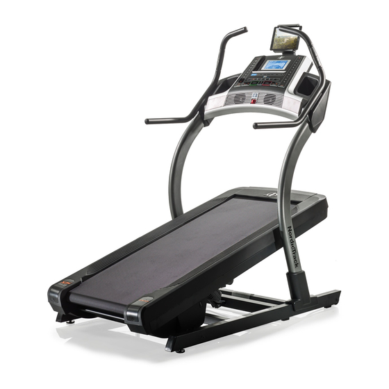
BEFORE YOU BEGIN Thank you for selecting the revolutionary reading this manual, please see the front cover of this NORDICTRACK X7i INCLINE TRAINER. The X7i manual. To help us assist you, note the product model ® INCLINE TRAINER offers a selection of features number and serial number before contacting us. -
Page 8: Part Identification Chart
PART IDENTIFICATION CHART Use the drawings below to identify small parts used for assembly. The number in parentheses below each draw- ing is the key number of the part, from the PART LIST near the end of this manual. The number following the key number is the quantity used for assembly. -
Page 9: Assembly
ASSEMBLY • Assembly requires two persons. • To identify small parts, see page 8. • Place all parts in a cleared area and remove the • Assembly requires the following tools: packing materials. Do not dispose of the packing materials until you fi nish all assembly steps. the included hex keys •... - Page 10 3. Remove and save the four 3/8" x 2 3/4" Screws (22) from the Uprights (83). 4. Set the Uprights (83) on the Base (74). Make sure that the hole with the Upright Wire (75) is on the right side. Attach the right Upright (83) to the Base (74) with two of the 3/8"...
- Page 11 5. See the inset drawing. Connect the Base Wire (52) to the Upright Wire (75). The connectors should slide together easily and snap into place. If they do not, turn one connector and try again. IF YOU DO NOT CONNECT THE CON- NECTORS PROPERLY, THE CONSOLE MAY BECOME DAMAGED WHEN YOU TURN ON THE POWER.
- Page 12 7. Slide the Right Inside Upright Cover (70) against the lower end of the right Upright (83). Press the Right Outside Upright Cover (71) against the Right Inside Upright Cover until it snaps into place. Make sure that the wires are not pinched.
- Page 13 9. If necessary, move the incline trainer to the desired location (see HOW TO MOVE THE INCLINE TRAINER on page 24). After the incline trainer is placed in the location where it will be used, make sure that the incline trainer rests firmly on the floor.
-
Page 14: The Chest Heart Rate Monitor
THE CHEST HEART RATE MONITOR HOW TO PUT ON THE HEART RATE MONITOR • Store the heart rate monitor in a warm, dry place. Do not store the heart rate monitor in a plastic bag or If the heart rate monitor looks like the one shown other container that may trap moisture. -
Page 15: How To Use The Incline Trainer
HOW TO USE THE INCLINE TRAINER HOW TO CONNECT THE POWER CORD nominal 120-volt circuit capable of carrying 15 or more amps. To avoid overloading the circuit, do Use a Surge Suppressor not plug other electrical devices, except for low- power devices such as cell phone chargers, into Your incline trainer, like other electronic equipment, the surge suppressor or into an outlet on the same... - Page 16 CONSOLE DIAGRAM STA RT STO P IN CL IN E SP EE D Q U IC K Q U IC K IN C L IN E S P E E D FEATURES OF THE CONSOLE To turn on the power, see page 17. To use the man- ual mode, see page 17.
- Page 17 HOW TO TURN ON THE POWER HOW TO USE THE MANUAL MODE IMPORTANT: If the incline trainer has been 1. Insert the key into the console. exposed to cold temperatures, allow it to warm to room temperature before you turn on the power. If See HOW TO TURN ON THE POWER at the left.
- Page 18 4. Change the incline of the incline trainer as The My Trail tab will show a track that represents desired. 1/4 mile (400 m). As you exercise, the fl ashing rectangle will show your progress. The My Trail tab To change the incline of the incline trainer, press will also show the number of laps you complete.
- Page 19 Before using 8. When you are fi nished exercising, remove the the handgrip key from the console. heart rate monitor, Step onto the foot rails, press the Stop button, and remove the adjust the incline of the incline trainer to zero. sheets of The incline must be at zero or you may damage plastic from...
- Page 20 3. Start the workout. Note: The calorie goal is an estimate of the number of calories that you will burn during Press the Start button or the Speed increase button the workout. The actual number of calories to start the workout. A moment after you press the that you burn will depend on various factors button, the incline trainer will automatically adjust to such as your weight.
- Page 21 HOW TO CONNECT YOUR SMART DEVICE TO THE HOW TO CONNECT YOUR HEART RATE MONITOR CONSOLE TO THE CONSOLE The console supports BLUETOOTH connections to The console is compatible with all BLUETOOTH Smart smart devices via the iFit app and to compatible heart heart rate monitors.
- Page 22 THE SETTINGS MODE HOW TO USE THE TABLET HOLDER The console features a settings mode that keeps track IMPORTANT: The tablet holder is designed for use of incline trainer information and allows you to person- with most full-size tablets. Do not place any other alize console settings.
-
Page 23: Fcc Information
FCC INFORMATION This console has been tested and found to comply with the limits for a Class B digital device, pursuant to part 15 of the FCC Rules. These limits are designed to provide reasonable protection against harmful interference in a residential installation. This equipment generates, uses, and can radiate radio frequency energy and, if not installed and used in accordance with the instructions, may cause harmful interference to radio communications. -
Page 24: How To Move The Incline Trainer
HOW TO MOVE THE INCLINE TRAINER Before moving the incline trainer, insert the key Carefully roll the incline trainer on the wheels to the into the console, adjust the incline level to zero, desired location, and then lower it to the level position. remove the key, and unplug the power cord. -
Page 25: Maintenance And Troubleshooting
MAINTENANCE AND TROUBLESHOOTING MAINTENANCE b. After the power cord has been plugged in, make sure that the key is inserted into the console. Regular maintenance is important for optimal perfor- mance and to reduce wear. Inspect and properly tighten c. Check the power switch located on the incline all parts each time the incline trainer is used. - Page 26 SYMPTOM: The walking belt slows when walked on SYMPTOM: The walking belt is off-center or slips when walked on a. Use only a surge suppressor that meets all of the specifications described on page 15. a. If the walking belt is off-center, first adjust the incline to 40 percent.
- Page 27 SYMPTOM: The incline of the incline trainer does SYMPTOM: The tablet holder does not stay in place not change correctly a. Rotate the tablet holder backwards. Then, tighten a. Hold down the Stop button and the Speed increase the indicated screw slightly until the tablet holder button, insert the key into the console, and then stays in place when it is rotated to the desired release the Stop button and the Speed increase...
-
Page 28: Exercise Guidelines
EXERCISE GUIDELINES Burning Fat—To burn fat effectively, you must exer- WARNING: cise at a low intensity level for a sustained period of Before beginning this time. During the first few minutes of exercise, your or any exercise program, consult your physi- body uses carbohydrate calories for energy. - Page 29 SUGGESTED STRETCHES The correct form for several basic stretches is shown at the right. Move slowly as you stretch —never bounce. 1. Toe Touch Stretch Stand with your knees bent slightly and slowly bend forward from your hips. Allow your back and shoulders to relax as you reach down toward your toes as far as possible.
-
Page 30: Part List
PART LIST Model No. NTL14215.1 R1115B Key No. Qty. Description Key No. Qty. Description 3/8" x 5 1/2" Screw Spring 3/8" x 3 3/4" Screw Cushion 3/8" Star Washer Base Wire #8 x 3/4" Tek Screw Rubber Cushion #8 x 3/4" Screw Large Pivot Bushing 3/8"... -
Page 31: Exploded Drawing
EXPLODED DRAWING A Model No. NTL14215.1 R1115B... - Page 32 EXPLODED DRAWING B Model No. NTL14215.1 R1115B...
- Page 33 EXPLODED DRAWING C Model No. NTL14215.1 R1115B...
- Page 34 EXPLODED DRAWING D Model No. NTL14215.1 R1115B...
- Page 35 EXPLODED DRAWING E Model No. NTL14215.1 R1115B...
-
Page 36: Ordering Replacement Parts
ORDERING REPLACEMENT PARTS To order replacement parts, please see the front cover of this manual. To help us assist you, be prepared to provide the following information when contacting us: • the model number and serial number of the product (see the front cover of this manual) •...