
Related Manuals for Interlogix TruVision Series TVQ-8101


Summary of Contents for Interlogix TruVision Series TVQ-8101
-
Page 1: Installation Guide
TruVision Wi-Fi IP Camera ® Installation Guide P/N 1073278-EN • REV A • ISS 09MAY17 © 2017 United Technologies Corporation. All rights reserved. -
Page 2: Table Of Contents
Contents Product overview ..................3 Installation environment ................3 Cable requirements ................4 Package contents ..................4 TruVision Wi-Fi IP Bullet Camera ............. 4 TruVision Wi-Fi IP Desktop Camera ..........5 Camera description – Bullet Camera ............6 Camera description – Desktop Camera ........... 7 Desktop camera LED indicators ............ -
Page 3: Product Overview
Product overview ® This is the installation guide for the following TruVision camera models: TVQ-8101 (1080p IP Wi-Fi Desktop IR camera) TVB-8101 (1080p IP Wi-Fi Bullet IR camera) Installation environment When installing the product, consider these factors: Electrical: Electrical wiring should be installed carefully by qualified service personnel. -
Page 4: Cable Requirements
Cable requirements For proper operation, adhere to the following cable and power requirements for the cameras. Category 5 cabling or better is recommended. All network cabling must be installed according to applicable codes and regulations. Package contents Check the package and contents for visible damage. If any components are damaged or missing, do not attempt to use the unit;... -
Page 5: Truvision Wi-Fi Ip Desktop Camera
TruVision Wi-Fi IP Desktop Camera IP Desktop Camera Installation Guide WEEE and Battery Installation Configuration CD Anchors and Screws Mounting Template CAUTION: Use direct plug-in UL listed power supplies marked Class 2/CE certified or LPS (limited power source) of the required output rating as listed on the unit. -
Page 6: Camera Description - Bullet Camera
Camera description – Bullet Camera Adjustment nut LED indicator Mounting base Micro SD card slot Main body Ethernet interface Sun shield 10. Power cable (12 VDC) Lens 11. GND screw WPS/RESET button P/N 1073278-EN • REV A • ISS 09MAY17 © 2017 United Technologies Corporation. All rights reserved. -
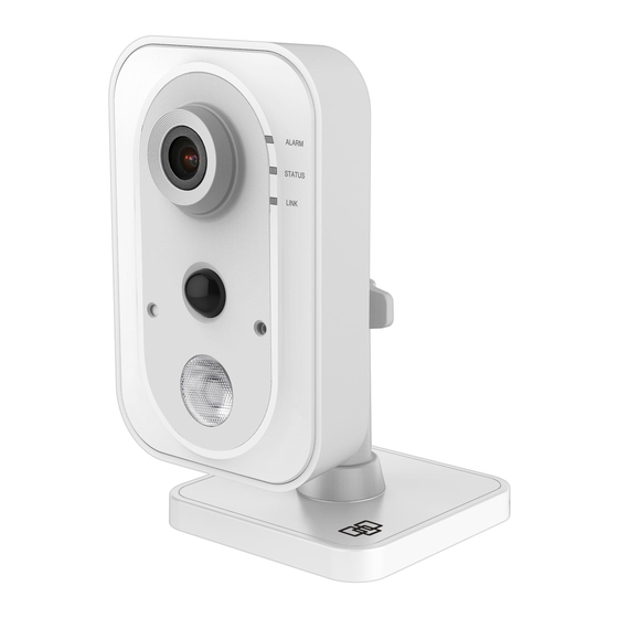
Page 7: Camera Description - Desktop Camera
Camera description – Desktop Camera Lens Ethernet interface Microphone 10. WPS/RESET button IR (infrared) LED 11. I: Alarm input interface LED indicators (see next 12. G: Grounding page) 13. O: Alarm output PIR (passive infrared) sensor interface Light sensor 14. Power supply port (12 VDC) Micro SD card slot 15. -
Page 8: Desktop Camera Led Indicators
Desktop camera LED indicators The following table describes the desktop camera LED behavior (see item 4 in “Camera description – Desktop Camera” on page State Color Appearance Alarm Camera alarm triggered Solid Camera alarm not triggered Blue Solid Link WPS in process Blue Fast blinking Blue... -
Page 9: Installing A Micro Sd Card
Installing a Micro SD card Micro SD cards with up to 128 GB of storage capacity can be installed in the cameras. Bullet Camera To access the Micro SD card slot, remove the cover on the bottom of the camera. Desktop Camera P/N 1073278-EN •... -
Page 10: Mounting
Mounting Before mounting a camera: Ensure that all the related equipment is powered off during the physical installation/camera mounting. Ensure that the wall or ceiling is strong enough to withstand four times the weight of the camera assembly. Bullet Camera To mount the bullet camera on a wall or ceiling: 1. -
Page 11: Waterproof Jacket Assembly
b. Adjust the pan direction [0°~360°]. c. Adjust the tilt direction [0°~90°]. d. Rotate the camera [0~360°] to adjust the lens to the surveillance angle. e. Tighten the adjustable nut (1) to complete the installation. Waterproof jacket assembly We recommended using the waterproof jacket to protect network cabling when the camera is installed outdoors. -
Page 12: Desktop Camera
Desktop Camera To mount the desktop camera on a magnetic surface: Place the base of the camera on a magnetic surface to hold the camera in place. WARNING: Magnetic fields can erase data on a credit card and cause damage to cell phones and hard drives. To mount the desktop camera on a wall or ceiling: 1. -
Page 13: Browser Requirements
4. Install the base on the fixed tray. 5. Install the camera on the bracket. 6. Adjust the camera angle by doing the following: a. Loosen the knob (1) to adjust the panning position and tilting position. b. When finished adjusting the camera angle, fasten the knob. Browser requirements The following browsers are supported for camera setup: ... -
Page 14: Quick Setup
Quick setup Note: If the light source where the camera is installed experiences rapid, wide variations in lighting, the camera may not operate as intended. To quickly put the camera into operation: 1. Mount the camera. (See “Mounting” on page 10) 2. -
Page 15: Add Cameras To A Wi-Fi Network
75-85 – Very Good: No additional actions are required to increase signal strength. It is not recommended to increase video resolution settings. 65-75 – Good: We recommend using a Wi-Fi repeater or powerline adapter to increase signal strength. Alternatively, video resolutions settings may be reduced to minimize poor video quality. -
Page 16: Reboot Cameras
Camera's default IP address: 192.168.2.70 User Name: admin Password: 1234 Note: A pop-up may appear asking for an immediate password change. We strongly recommend changing the password. Select OK in this dialog and any subsequent dialogs that may appear. 6. -
Page 17: Alternative Methods Of Adding Cameras
2. Connect the camera to a router with an Ethernet cable. 3. Launch TruVision Device Manager. Note: Install TruVision Device Manager using the included CD or download it from www.interlogix.com/video. 4. Verify that the camera is found in the main camera selection window. 5. Select the camera to be configured. -
Page 18: Add Cameras Via Wps
b. Click the Test button to ensure that the IP address is not already assigned to another device in the network. 11. Click Save on the bottom of the screen. 12. Power cycle the camera. See “3. Reboot cameras” on page Add cameras via WPS A WPS-enabled wireless router is required to add a camera using the WPS function. -
Page 19: Change Default Camera Settings
TruVision cameras are compatible with TruVision Navigator video management system software, which delivers powerful centralized and remote video management capabilities. Note: Go to www.interlogix.com/video to download TruVision Device Manager and TruVision Navigator. See the TruVision Device Manager User Manual and the TruVision Navigator User Manual for further information and capabilities. -
Page 20: Reset Cameras To Factory Default
Reset cameras to factory default If required, a camera can be reset to the factory default settings. Reset button 1. Remove the camera cover, press and hold the WPS/RESET button, and then remove power from the camera. 2. Apply power to the camera and continue holding the WPS/RESET button for 20 seconds. -
Page 21: Troubleshooting
Troubleshooting Troubleshooting/FAQ The camera does not appear in the list of Wi-Fi networks. Cause Solution The camera takes up to 90 Wait until the camera boots up seconds to boot up. before checking the Wi-Fi list. An Ethernet cable is connected Disconnect the Ethernet cable to the camera. -
Page 22: Specifications
Specifications TruVision Wi-Fi IP Bullet Camera Electrical Voltage input 12 VDC, PoE (IEEE 802.3af) Power consumption Max. 5.8 W Wi-Fi parameters Wi-Fi standard IEEE802.11b/g/n Frequency range 2.4 to 2.4835 GHz Communication Support 20/40 MHz bandwidth Security 64/128-bit WEP, WPA/WPA2, WPA-PSK/WPA2-PSK, WPS Transmission rate 11b: 11Mbps, 11g: 54Mbps, 11n: up to 150Mbps... -
Page 23: Truvision Wi-Fi Ip Desktop Camera
TruVision Wi-Fi IP Desktop Camera Electrical Voltage input 12 VDC, PoE (IEEE 802.3af) Power consumption Max. 4.5 W Wi-Fi parameters Wi-Fi standard IEEE802.11b/g/n Frequency range 2.4 to 2.4835 GHz Communication Support 20/40 MHz bandwidth Security 64/128-bit WEP, WPA/WPA2, WPA-PSK/WPA2-PSK, WPS Transmission rate 11b: 11 Mbps, 11g: 54 Mbps, 11n: 150 Mbps... - Page 24 Copyright © 2017 United Technologies Corporation. Interlogix is part of UTC Climate, Controls & Security, a unit of United Technologies Corporation. All rights reserved. Trademarks and The TruVision name and logo is a trademark of patents United Technologies. Trade names used in this document may be...
- Page 25 environment. In order to avoid the possibility of exceeding the FCC radio frequency exposure limits, human proximity to the antenna shall not be less than 20 cm (8 inches) during normal operation. CAUTION: Changes or modifications not expressly approved by UTC for compliance could void the user’s authority to operate the equipment.
- Page 26 aux deux conditions suivantes : (1) l'appareil ne doit pas produire de brouillage, et (2) l'utilisateur de l'appareil doit accepter tout brouillage radioélectrique subi, même si le brouillage est susceptible d'en compromettre le fonctionnement. RS-3230/RS-3231/TVQ-8101 complies with IC requirements, IC: 20201-RS323X. RS-3250/RS-3251/TVB-8101 complies with IC requirements, IC: 20201-RS325X.
- Page 27 For more information see: www.recyclethis.info. Contact information For contact information, see www.interlogix.com or www.utcfssecurityproducts.eu. P/N 1073278-EN • REV A • ISS 09MAY17 © 2017 United Technologies Corporation. All rights reserved.
- Page 28 Annex 3 B and A Wideband Data Transmission systems 2400.0-2483.5 MHz: Country Restriction Reasons/remarks Norway Implemented This subsection does not apply for the geographical area within a radius of 20 km from the centre of Ny-Ålesund. Italy Implemented The public use is subject to general authorization by the respective service provider.
- Page 29 THAT THERE WILL BE NO DEATH, PERSONAL INJURY, AND/OR PROPERTY DAMAGE AS A RESULT. WHILE INTERLOGIX UNDERTAKES TO REDUCE THE PROBABILITY THAT A THIRD PARTY MAY HACK, COMPROMISE OR CIRCUMVENT ITS SECURITY PRODUCTS OR RELATED SOFTWARE, ANY SECURITY PRODUCT OR SOFTWARE MANUFACTURED, SOLD OR LICENSED BY INTERLOGIX, MAY STILL BE HACKED, COMPROMISED AND/OR CIRCUMVENTED.