
Related Manuals for Interlogix TruVision 6 Series


Summary of Contents for Interlogix TruVision 6 Series
- Page 1 TruVision Series 6 IP Camera Installation Guide P/N 1073465-EN • REV B • ISS 13DEC18...
- Page 2 © 2018 United Technologies Corporation, Copyright Interlogix is part of UTC Climate, Controls & Security, a unit of United Technologies Corporation. All rights reserved. Information in this document is subject to change Disclaimer without notice. No part of this document may be...
- Page 3 This device complies with Part 15 of the FCC Rules. FCC conditions Operation is subject to the following two conditions: (1) This device may not cause harmful interference. (2) This Device must accept any interference received, including interference that may cause undesired operation.
- Page 4 QR code: For contact information and to download the latest Contact information manuals, tools, and firmware, go to the web site of your and manuals/ tools/ region. firmware Americas: www.interlogix.com EMEA: www.firesecurityproducts.com Manuals are available in several languages. Australia/New Zealand: www.utcfs.com.au...
- Page 5 Safety instructions These instructions are intended to ensure that user can use the product correctly to avoid danger or property loss. The precaution measures are divided into “Warnings” and “Cautions”. Warnings: Warning messages advise you of hazards that could result in injury or loss of life. They tell you which actions to take or to avoid in order to prevent the injury or loss of life.
- Page 6 • Please make sure that the plug is firmly connected to the power socket. When the device is mounted on a wall or ceiling, it should be firmly fixed to the surface. • If smoke, odor or noise rises from the device, turn off the power at once and unplug the power cable.
- Page 7 • To avoid heat accumulation, good ventilation is required for operating environment. • Keep the camera away from liquid while in use. • During delivery, the camera shall be packed in its original packing, or packing of the same texture. •...
-
Page 8: Table Of Contents
Content Introduction 6 Product overview 6 Contact information and manuals /tools /firmware 8 Installation 9 Installation environment 10 Package contents 11 Cable requirements 24 Camera description 25 Setting up the camera 33 IR illuminators 33 Accessing the Micro SD card 34 Mounting the bullet camera 34 Mounting the turret camera 40 Mounting the dome camera 47... - Page 9 TruVision IP fixed lens turret dome 72 TruVision IP motorized lens turret dome 73 TruVision IP fixed lens dome cameras 73 TruVision IP motorized lens dome cameras 74 TruVision IP fixed lens wedge cameras 75 Pin definitions 76 Installation Guide...
-
Page 10: Introduction
Introduction Product overview This is the installation guide for TruVision Series 6 IP camera models: TVB-5601 (2MPX IP fixed lens bullet camera) TVB-5602 (4MPX IP fixed lens bullet camera) TVB-5603 (8MPX IP fixed lens bullet camera) TVB-5604 (2MPX IP motorized lens bullet camera) ... - Page 11 TVT-5610 (4MPX IP motorized lens turret camera, white) TVT-5611 (8MPX IP motorized lens turret camera, gray) TVD-5601 (2MPX IP fixed lens dome camera) TVD-5602 (4MPX IP fixed lens dome camera) TVD-5603 (8MPX IP fixed lens dome camera) ...
-
Page 12: Contact Information And Manuals /Tools /Firmware
Contact information and manuals /tools /firmware For contact information and to download the latest manuals, tools, and firmware, go to the web site of your region: Americas: www.interlogix.com EMEA: www.firesecurityproducts.com Manuals are available in several languages. Australia/New www.utcfs.com.au Zealand: Installation Guide... -
Page 13: Installation
Installation This section provides information on how to install the cameras. Before you start: • Make sure the device in the package is in good condition and all the assembly parts are included. • The standard power supply is 12 VDC or PoE (802.3 af). Please make sure your power supply matches with your camera. -
Page 14: Installation Environment
Installation environment When installing your product, consider these factors: Electrical: Install electrical wiring carefully. It should be • done by qualified service personnel. Always use a proper PoE switch or a 12 VDC UL listed Class 2 or CE certified power supply to power the camera. -
Page 15: Package Contents
Package contents Check the package and contents for visible damage. If any components are damaged or missing, do not attempt to use the unit; contact the supplier immediately. If the unit is returned, it must be shipped back in its original packaging. IP fixed lens bullet camera Camera 12 VDC connector:... - Page 16 Screws Torx wrench • • Drywall anchor 7.5 × 24.5 mm (3 pcs) Screw M4 × 25 mm (3 pcs) Installation guide Equipment disposal • • sheet Battery disposal sheet • Installation Guide...
- Page 17 IP motorized lens bullet camera Camera Mounting adapter plate • • 83.5 mm (3.29 in.) 40 mm (1.57 in.) Screws Video test cable • • Drywall anchor 7.5 × 24.5 mm (4 pcs) Screw M4 × 25 mm (4 pcs) Installation guide Equipment disposal •...
- Page 18 Battery disposal Torx wrench • • sheet Cable routing tool Adapter ring for G3/4 • • Back box Screws for the back • • 144.1 mm (5.67 in 3.5 mm (0.14 in.) 2 mm 9 mm (0.35 in.) (0.08 in.) G3/4 cable adapter •...
- Page 19 IP fixed lens turret camera Camera 12 VDC connector: • • Two terminal connector with positive and negative indicators. Camera drill template Protective water • • resistant RJ45 connector cover: Provides water resistance to network cable connector. Adapter plate • Screws •...
- Page 20 Torx wrench Screw PM4 × 8 • • (3pcs) Screw PM6-32 × 10 Screw KM4 × 8 • • (4 pcs, used to attach (4 pcs, used to the turret camera to a 2 attach the adapter to Gang electrical box) the brackets) Installation guide Installation guide of...
- Page 21 IP motorized lens turret camera Camera Mounting adapter plate • • 83.5 mm (3.29 in.) 36 mm (1.42 in.) Screws Torx wrench • • Drywall anchor 7.5 × 24.5 mm (4 pcs) Screw M4 × 25 mm (4 pcs) Installation Battery disposal sheet •...
- Page 22 Equipment • disposal sheet IP fixed lens dome camera Camera 12 VDC connector: • • Two terminal connector with positive and negative indicators. Screws • Camera drill template • Drywall anchor 7.5 × 24.5 mm (3 pcs) Screw M4 × 25 mm (3 pcs) Installation Guide...
- Page 23 Torx wrench Water joint: Provides • • water resistance to network cable connector. Toggle bolt (3 pcs) Gray cloth • • Installation guide Equipment disposal • • sheet Battery disposal sheet • Installation Guide...
- Page 24 IP motorized lens dome camera Camera Mounting adapter plate • • 46 mm (1.81 in.) 45 mm (1.77 in.) 140 mm (5.51 in.) 31.5 mm (1.24 in.) Screws • Video test cable • Drywall anchor 7.5 × 24.5 mm (4 pcs) Screw M4 ×...
- Page 25 Adapter ring for G3/4 Gray cloth • • Installation guide Equipment disposal • • sheet Battery disposal sheet G3/4 cable adapter • • (mm) Installation Guide...
- Page 26 IP fixed lens wedge camera Camera 12 VDC connector: • • Two terminal connector with positive and negative indicators. Screws • Screws: M4 × 8 (3 pcs) • Drywall anchor Used for mounting the 7.5 × 24.5 mm (3 pcs) wedge to the adapter plate Screw...
- Page 27 Torx wrench Gray cloth • • Installation guide Equipment disposal • • sheet Battery disposal sheet • Caution: Use direct plug-in UL listed power supplies marked Class 2/CE certified or LPS (limited power source) of the required output rating as listed on the unit. Installation Guide...
-
Page 28: Cable Requirements
Caution: Risk of explosion if the battery is replaced by an incorrect type. Dispose of used batteries according to the instructions. Cable requirements For proper operation, adhere to the following cable and power requirements for the cameras. Category 5 cabling or better is recommended. -
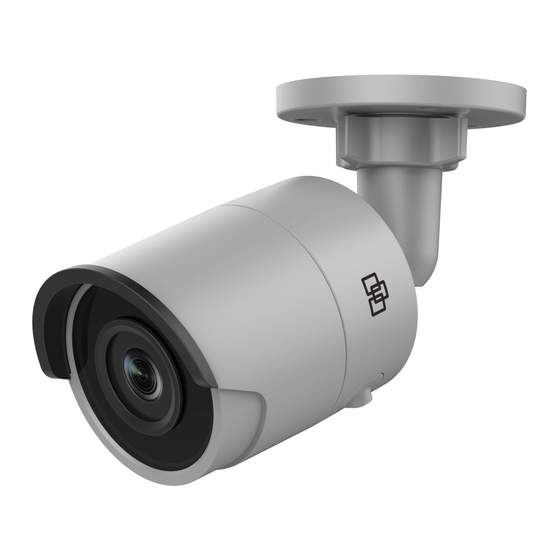
Page 29: Camera Description
Camera description Figure 1: IP fixed lens bullet camera Adjustable bracket 12 VDC power Back housing Reset button Front housing Micro SD card slot Lens 10. Grounding screw Sunshield 11. Serial port (factory use) Ethernet RJ45 PoE port Note: To reset the camera to default settings, press and hold the RESET button and power on the camera. - Page 30 Figure 2: IP motorized lens bullet camera Alarm 1 input /1 output Audio 1 output (line (up to 12 VDC, 30 mA) out) 12 VDC power Reset button Ethernet RJ45 PoE Micro SD card slot port 960H analog output Audio 1 input (line in/mic in) Note: To reset the camera to default settings, press and hold the RESET button and power on the camera.
- Page 31 Figure 3: IP fixed lens turret camera 8MPx 2MPx / 4MPx Lens assembly Ethernet RJ45 PoE port Trim ring Reset button Housing Serial port (factory Base use) 12 VDC power Micro SD card slot Note: To reset the camera to default settings, press and hold the RESET button and power on the camera.
- Page 32 Figure 4: IP motorized turret camera Housing Audio 1 input (line in/mic in) Black rubber protective cover 10. Audio 1 output (line out) Rubber inserts 11. GND for alarm output Removable cable access door 12. Alarm 1 output (up to 12VDC, 30mA) Trim ring 13.
- Page 33 GND for 12 VDC 14. Alarm 1 input power 15. Reset button Positive pole for 12 16. Micro SD card slot VDC power 17. SD card cover Ethernet RJ45 PoE port Note: To reset the camera to default settings, press and hold the RESET button and power on the camera.
- Page 34 Figure 5: IP fixed lens dome camera 12 VDC power Base Audio 1 input (line in/mic Dome liner in) / 1 output (line out) Lens Alarm 1 input/1 output (up Housing cover to 12 VDC, 30 mA) SD card slot Ethernet RJ45 PoE port 10.
- Page 35 has started up, hold the RESET button for an additional 20 seconds. Figure 6: IP motorized lens dome camera IP motorized lens dome camera parts Housing cover Lens assembly Audio 1 input (line in/mic Reset button in) / 1 output (line out) Micro SD card slot Alarm 1 input/1 output (up Back box...
- Page 36 Figure 7: IP fixed lens wedge camera Housing cover Alarm 1 input/1 output Lens assembly 12 VDC power Camera assembly 10. Ethernet RJ45 PoE MIC (microphone) port Reset button 11. IR illuminators Micro SD card slot 12. Ground Audio 2 inputs. Line in or MIC (built-in microphone) / 1 output Installation Guide...
-
Page 37: Setting Up The Camera
Note: To reset the camera to default settings, press and hold the RESET button and power on the camera. After the camera has started up, hold the RESET button for an additional 20 seconds. Setting up the camera Note: If the light source where the camera is installed experiences rapid, wide-variations in lighting, the camera may not operate as intended. -
Page 38: Accessing The Micro Sd Card
The visible IR range may vary due to multiple factors such as weather, IR reflection level of objects in frame, lens adjustment, and camera settings. Please refer to the camera datasheet for the standard IR range. Note: Avoid installing the IR camera closely facing a solid object such as a tree or wall. - Page 39 Loosen the large nut at the base of the mounting bracket to adjust the camera’s viewing angle. Pan direction: 0 to 360° adjustable Tilt direction: 0 to 90° adjustable Rotate direction: 0 to 360° adjustable Adjust the lens to the desired surveillance angle. Tighten the adjustable nuts to complete the installation.
- Page 40 Secure the mounting adapter plate to the wall/ceiling with the screws. Loosen the screws to remove the back box. Installation Guide...
- Page 41 Route the cables through the sealing plugs in the back box. Pierce the sealing plugs on the back box. Thread cables through the sealing plugs. Note: • For RJ45 network interface, use the supplied cable routing tool. • For the audio interface, first thread the audio cable through the sealing plug and then connect the audio connector to the cable.
- Page 42 Drag the sealing plug Valgus back Secure the back box in the wall/ceiling with screws. Hook the camera to the back box with the safety lanyard and connect the cables to the camera. Installation Guide...
- Page 43 Secure the camera to the back box with the screws. Adjust the viewing angle. 3-axis adjusting (pan/tilt/rotation) allows you to adjust for optimum camera rotation and placement. Follow the steps below to adjust the viewing angle. Loosen the lock screw using the supplied wrench. Installation Guide...
-
Page 44: Mounting The Turret Camera
Adjust the view angle of the camera. The adjusting range of the panning is from 0° to 360°, the tilting is from 0° to 90° and the rotation is from 0° to 360°. Tighten the lock screw. Lock screw Mounting the turret camera To mount the fixed lens turret camera on a surface: Place the drill template (supplied) on the surface where the camera is to be mounted. - Page 45 An adapter plate is provided if installing the turret camera to a wall mount or other accessory. Install the adapter plate to the accessory with three PM4X8 screws, referencing number “2”. Rotate the trim ring counterclockwise to remove it from the camera.
- Page 46 Rotate the lens assembly to adjust the pan angle. Rotate the lens assembly to adjust the tilt angle. Tighten the Torx screw to secure the lens at the desired surveillance angle. Torx screw Attach the trim ring to the camera and rotate it clockwise to secure it.
- Page 47 To mount the motorized lens turret camera on a ceiling or wall: Using the turret adapter plate, mark the mounting holes for the plate. Use the four holes labeled with the number Secure the mounting adapter to the mounting surface with the supplied screws.
- Page 48 Front Hook the camera to the adapter with the safety lanyard. Safety lanyard Connector access cover To access the connectors, loosen the two screws using the Torx wrench and lift up on the access cover. The black rubber insert at the edge of the access cover is required to maintain the IP67 rating.
- Page 49 access for the cables that will be connected to the camera. Black rubber insert Note: When routing the cables, remove the whole rubber sealing, then remove the sealing pillar, and then insert the wire. Otherwise, keep the sealing plug intact. Once all the cable connections are made, lower the access cover and tighten the Torx screws.
- Page 50 Locking Torx screw Adjust the lens position. To adjust the lens position, remove the decorative trim ring by rotating the ring towards the unlocked position (see reference on the trim ring). Loosen the lens adjustment Torx screw that is now visible. Lens adjustment Torx screw Rotate the lens assembly to adjust the pan tilt angle.
-
Page 51: Mounting The Dome Camera
0°~360° 0°~360° 0°~75° Reinstall the trim ring on the camera, and rotate it clockwise to secure. To mount the motorized lens turret camera on a wall: Please refer to the installation guide provided with the TVD- CB6 mounting kit for instructions on mounting the motorized lens turret camera to the wall. - Page 52 referencing the letter “A” on the drill template. Skip this step if you want to route the cables on the surface. Using the supplied Torx wrench, remove the dome bubble assembly. Screw Installation Guide...
- Page 53 Install the dome on the mounting surface using the supplied hardware. Loosen the tilt adjust screws (see image below) and adjust the tilt position of the lens assembly within a range of 75 degrees. Retighten the tilt adjust screws. Rotate the dome liner to adjust the pan position within a range of 355 degrees.
- Page 54 (Optional) If using a micro SD card (not included): To remove the SD card, push the micro SD card forward. The micro SD card will spring out. SD slot Reinstall the dome housing and tighten the Torx screws. Installation Guide...
- Page 55 To mount the motorized lens dome camera on a ceiling: Lift the camera body to separate it from the back box and the mounting adapter plate. Separate the back box and the mounting adapter plate from each other. Unscrew the bubble from the camera body. Installation Guide...
- Page 56 Mark four screw holes at desired mounting location using the holes labeled number “2” on the mounting adapter plate. Secure the mounting adapter plate to ceiling with the four supplied screws. Note: Use expansion screws for a concrete ceiling and self-tapping screws for a wooden ceiling.
- Page 57 Route the cables through the sealing plugs in the back box. Pierce the sealing plugs on the back box. Thread cables through the sealing plugs. Note: • For RJ45 network interface, use the supplied cable routing tool. • For the audio interface, first thread the audio cable through the sealing plug and then connect the audio connector to the cable.
- Page 58 Drag the sealing Valgus plug back Align the “FRONT” marks on the back box and mounting adapter plate. Secure the back box to the mounting adapter plate with three screws. Installation Guide...
- Page 59 Hang the camera body on the safety lanyard. Connect the cables to corresponding plugs on the camera base. 10. Fix the camera body to the back box with three screws. Installation Guide...
- Page 60 11. Loosen the tilt adjust screws and adjust the tilt position of the lens assembly within a range of 75 degrees. Retighten the tilt adjust screws. Rotate the dome liner to adjust the pan position within a range of 355 degrees. Rotate the lens assembly (0 to 355°) to obtain the desired surveillance angle.
-
Page 61: Mounting The Wedge Camera
12. Reattach the bubble back to the camera body and tighten the Torx screw To mount the motorized lens dome camera on a wall: Please refer to the installation guide provided with the TVD- CB7 mounting kit for instructions on mounting the motorized lens dome camera to the wall. - Page 62 Secure the adapter plate to the mounting surface using the drill template. Note: If required, remove the knockout on the side of the adapter plate to allow for cable access. Knockout Loosen the Torx screws with a Torx wrench (supplied) to remove the bubble assembly.
- Page 63 Mount the camera base to the adapter plate or directly to the mounting surface. Loosen the locking screw, located beside the RESET button using the Phillips screwdriver. Adjust the view angle of the camera. The adjusting range of the panning is from -30°...
- Page 64 Reattach the bubble assembly to the camera base. Installation Guide...
-
Page 65: Using The Protective Water Resistant Connector Cover
Using the protective water resistant connector cover When installing a camera outdoors, it is recommended that the supplied protective water resistant RJ45 connector cover be used. Additional protection can be achieved by adding weather resistant tape, not supplied. Figure 8: Protective water resistant RJ45 connector cover components ①... - Page 66 on the RJ45 plug. Feed the network cable ⑦ through the screw cap ⑥, rubber gasket ⑤ (the flat portion of the rubber gasket goes towards the screw cap), and the protective connector sleeve ④ in the order shown in Figure 8.
- Page 67 a) Insert into Align the snap and notch b) Secure with . Camera Switch/Router To install the weather resistant tape (not supplied): Tightly wrap the tape around the RJ45 connector, as shown below. Keep in mind that the tape will stretch as you are wrapping the connector.
- Page 68 Note: Make sure that all bare wires are all firmly wrapped with the tape. Press down on the tape, at each end of the connector to ensure a weather resistant seal. Press Also wrap weather resistant tape around any cable that that has bare wires, as shown below.
-
Page 69: Network Access
Press Network access This guide explains how to configure the camera over the network with a web browser. TruVision IP cameras can be configured and controlled using Microsoft Internet Explorer (IE) and other browsers. The procedures described use Microsoft Internet Explorer web browser. - Page 70 To change the web browser’s security level: In Internet Explorer, click Internet Options on the Tools menu. On the Security tab, click the zone to which you want to assign a web site under “Select a web content zone to specify its security settings”.
-
Page 71: Activating The Camera
To add the camera’s IP address to Internet Explorer’s list of trusted sites: Open Internet Explorer. Click Tools, and then Internet Options. Security Trusted sites Click the tab, and then select the icon. Click the Sites button. Clear the “Require server verification (https:) for all sites in this zone box”. - Page 72 Note: The default IP address of the camera is 192.168.1.70. For the camera to enable DHCP by default, you must activate the camera via TruVision Device Manager. Please refer to the following section, “Activation via TruVision Device Manager”. Enter the password in the password field.
- Page 73 Activation via TruVision Device Manager: Run TruVision Device Manager to search for online devices. Check the device status from the device list, and select the inactive device. Enter the password in the password field, and confirm it. Note: A valid password range must be between 8 and 16 characters.
-
Page 74: Using The Camera With A Truvision Recorder Or Another System
Using the camera with TruVision Navigator A camera must be connected to an Interlogix NVR in order to be operated by TruVision Navigator. Please refer to the TruVision Navigator user manual for instructions on operating the camera with TruVision Navigator. -
Page 75: Specifications
Specifications TruVision IP fixed lens bullet cameras Electrical Voltage input 12 VDC, PoE (IEEE 802.3af) Power consumption 2MPX: Max. 7.5 W 4MPX: Max. 7.5 W 8MPX: Max. 8 W Miscellaneous Connectors 12 VDC Power Input, Network Port (PoE) Operating temperature -30 to +60 °C (-22 to +140°F) 70 ×... -
Page 76: Truvision Ip Fixed Lens Turret Dome
Miscellaneous Connectors 12 VDC Power Input, Network Port (PoE+), Audio In/Out, Alarm In/Out, Operating temperature -30 to +60 °C (-22 to +140°F) Dimensions 144.13 × 332.73 mm (5.7 x 13.1 in.) Weight 1.74 kg (3.8 lbs.) Environmental rating IP67, IK10 TruVision IP fixed lens turret dome Electrical Voltage input... -
Page 77: Truvision Ip Motorized Lens Turret Dome
TruVision IP motorized lens turret dome Electrical Voltage input 12 VDC, PoE (IEEE 802.3af), Audio In/Out, Alarm In/Out Power consumption 2MPX: Max. 12.5 W 4MPX: Max. 12.5 W 8MPX: Max. 12.5 W Miscellaneous Connectors 12 VDC Power Input, Network Port (PoE) Operating temperature -30 to +60 °C (-22 to +140 °F) -
Page 78: Truvision Ip Motorized Lens Dome Cameras
Operating temperature -30 to +60 °C (-22 to 140°F) Dimensions 111 × 82.4 mm (4.4 × 3.2 in.) Weight 500 g (1.1 lbs.) Environmental rating IP67, IK10 TruVision IP motorized lens dome cameras Electrical Voltage input 12 VDC, PoE (IEEE 802.3af) Power consumption 2MPX: Max. -
Page 79: Truvision Ip Fixed Lens Wedge Cameras
TruVision IP fixed lens wedge cameras Electrical Voltage input 12 VDC, PoE (IEEE 802.3af) Power consumption 2MPX: Max. 10 W 4MPX: Max. 10 W Miscellaneous Connectors 12 VDC Power Input, Network Port (PoE) Operating temperature -30 to +60 °C (-22 to +140 °F) Dimensions 110 ×... -
Page 80: Pin Definitions
Pin definitions There are eight wires on a standard UTP/STP cable and each wire is color-coded. The following shows the pin allocation and color of straight and crossover cable connection: Figure 9: Straight-through cable White/Orange White/Orange Orange Orange White-Green White-Green Blue Blue White/Blue... - Page 81 Installation Guide...