
Related Manuals for Interlogix TVB-1101


Summary of Contents for Interlogix TVB-1101
-
Page 1: Installation Guide
TruVision 11/31 Series IP Camera Installation Guide P/N 1072857A-EN • REV 1.0 • ISS 29AUG14... - Page 2 © 2014 United Technologies Corporation, Copyright Interlogix is part of UTC Building & Industrial Systems, a unit of United Technologies Corporation. All rights reserved. Trademarks and Trade names used in this document may be trademarks patents or registered trademarks of the manufacturers or vendors of the respective products.
- Page 3 European Union. For proper recycling, return this product to your local supplier upon the purchase of equivalent new equipment, or dispose of it at designated collection points. For more information see: www.recyclethis.info. Contact information For contact information, see www.interlogix.com or www.utcfssecurityproducts.eu.
-
Page 5: Table Of Contents
Content Introduction 2 Product overview 2 Installation 4 Installation environment 4 Package contents 5 Cable requirements 11 Camera description 11 Setting up the camera 15 Accessing the SD card 16 Mounting the mini bullet camera 16 ... -
Page 6: Introduction
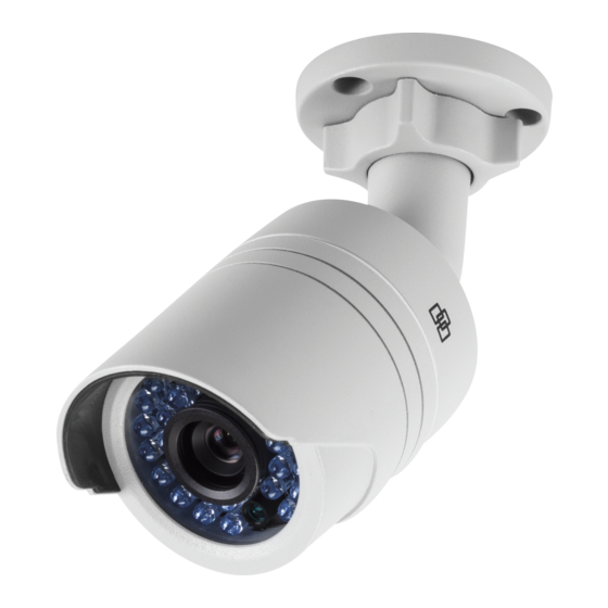
Introduction Product overview This is the installation guide for TruVision 11/31 Series IP camera models: TVB-1101 (1.3MPX bullet, 6mm lens, PAL) TVB-3101 (1.3MPX bullet, 6mm lens, NTSC) TVB-1102 (3MPX bullet, 6mm lens, PAL) TVB-3102 (3MPX bullet, 6mm lens, NTSC) ... - Page 7 TVD-3106 (3MPX indoor mini dome, PoE/12VDC, NTSC) TVW-1101 (1.3MPX wedge, 2.8mm lens, PAL) TVW-3101 (1.3MPX wedge, 2.8mm lens, NTSC) TVW-1102 (3MPX wedge, 2.8mm lens, PAL) TVW-3102 (3MPX wedge, 2.8mm lens, NTSC) TVW-1110 (3MPX wedge, 2.8mm lens, Marine, PAL) ...
-
Page 8: Installation
Installation This section provides information on how to install the cameras. Installation environment When installing your product, consider these factors: • Electrical: Install electrical wiring carefully. It should be done by qualified service personnel. Always use a proper PoE switch or a 12 VDC UL listed Class 2 or CE certified power supply to power the camera. -
Page 9: Package Contents
be used for an extended period of time, put on the lens cap to protect the sensors from dirt. Package contents Check the package and contents for visible damage. If any components are damaged or missing, do not attempt to use the unit;... - Page 10 Template Screws Water joint: provide water 12 VDC Connector: DC resistance to network jack socket to connection. terminal connectors with positive and negative indicators. IP indoor mini dome camera Camera Installation Guide...
- Page 11 Installation manual CD with Configuration manual and TruVision Device Finder Template Screws Water joint: provide water 12 VDC Connector: DC resistance to network jack socket to connection. terminal connectors with positive and negative indicators (TVD-1105 / 3105 / 1106 / 3106 only). Screws B Wrench Installation Guide...
- Page 12 IP VF dome camera Camera Installation manual CD with Configuration manual and TruVision Device Finder Template Screws Installation Guide...
- Page 13 Water joint: provide water 12 VDC Connector: DC resistance to network jack socket to connection. terminal connectors with positive and negative indicators. Video test cable Wrench Screws C: M4×19, 3pcs Adaptor IP wedge camera Camera Installation Guide...
- Page 14 Installation manual CD with Configuration manual and TruVision Device Finder Template Screws Water joint: provide water 12 VDC Connector: DC resistance to network jack socket to connection. terminal connectors with positive and negative indicators. Screws C: M4×8, 2pcs Wrench Installation Guide...
-
Page 15: Cable Requirements
Lens adjustment Converter pan CAUTION: Use direct plug-in UL listed power supplies marked Class 2/CE certified or LPS (limited power source) of the required output rating as listed on the unit. Cable requirements For proper operation, adhere to the following cable and power requirements for the cameras. - Page 16 Grounding screws Reset button Installation Guide...
- Page 17 Figure 2: IP indoor mini dome camera Base Ethernet RJ45 and BNC cable Lens Safety cable Dome liner Reset button Housing Note: TVD-1105 / 3105 / 1106 / 3106 cameras have a 12 VDC port. Installation Guide...
- Page 18 Figure 3: IP wedge camera Cover Base Lens Serial port SD card Reset button Ethernet RJ45 PoE port Converter pan Power supply Installation Guide...
-
Page 19: Setting Up The Camera
Figure 4: IP VF dome camera Dome liner Mounting plate Housing Reset button Ethernet RJ45 PoE port Analog video output Power supply 10. Serial port Audio and alarm cables 11. SD card Lens Setting up the camera Note: If the light source where the camera is installed experiences rapid, wide- variations in lighting, the camera may not operate as intended. -
Page 20: Accessing The Sd Card
Set up the camera’s network and streaming parameters so that the camera can be controlled over the network. For further information, please refer to the “TruVision IP Camera Configuration Manual”. Program the camera to suit its location. For further information, please refer to the “TruVision IP Camera Configuration Manual”. - Page 21 Ceiling Mounting Hole Hole Hole Secure the mounting base to the ceiling or wall with the supplied screws. Loosen the adjustable nuts on the bracket, and adjust the camera from P/R/T (pan/rotate/tilt) direction. P Direction: 0 to 360°adjustable. T Direction: 0 to 90°adjustable. R Direction: 0 to 360°adjustable Adjust the lens to the required surveillance angle.
-
Page 22: Mounting The Vf Dome Camera
0° ~ 3 6 0° 0° ~ 3 6 0° 0°~ 9 0° Mounting the VF dome camera To mount the VF dome camera on a ceiling or wall: Loosen the three screws on the edge of the lower dome with screw driver. - Page 23 Drill the three screw holes on the ceiling with the supplied drill template. Cable hole Screw holes Installation Guide...
- Page 24 If you want to route the cables inside the ceiling, drill a cable hole in the ceiling or wall using the drill template. Attach the camera to the ceiling or wall by aligning the housing holes with those in the ceiling. Secure the camera with the supplied screws as shown below.
- Page 25 panning position of the camera. Rotate the tilting axes to adjust the tilting position of the camera. Rotate the lens table to adjust the azimuth angle of the image. Zoom and focus adjustment. Loosen the zoom lever and move the lever between T(Tele) and W(Wide) to obtain the appropriate angle of view.
-
Page 26: Mounting The Indoor Mini Dome Camera
Mounting the indoor mini dome camera To mount the indoor mini dome camera on a ceiling: Drill the screw holes on the ceiling with the supplied drilling template. If you need to route the cables from the bottom of the camera, cut a cable hole in the ceiling. Using the supplied hex wrench, loosen the set screws to remove the dome enclosure. - Page 27 Note: If required, you can route cables through the side opening of the mounting base. Loosen the tilt lock screws, and adjust the tilting position in a range of 65 degrees. Retighten the tilt lock screws. Rotate the dome liner to adjust the panning position in a range of 360 degrees to obtain the desired surveillance angle.
-
Page 28: Mounting The Wedge Dome Camera
Reinstall the lower dome and tighten the screws. Mounting the wedge dome camera To mount the wedge dome camera on a ceiling: Drill the screw holes on the ceiling with the supplied drilling template. To route the cables from the base of the camera, cut a cable hole in the ceiling. - Page 29 Fix the camera base to the converter pan or mounting surface. Re-attach the dome enclosure to the camera. Installation Guide...
-
Page 30: Using The Camera With A Recorder
Using the camera with TruVision Navigator A camera must be connected to an Interlogix NVR or hybrid DVR in order to be operated by TruVision Navigator. Please refer to the TruVision Navigator user manual for instructions on operating the camera with the TruVision Navigator. -
Page 31: Specifications
Specifications TruVision IP mini bullet cameras Electrical Voltage input 12 VDC, PoE (IEEE 802.3af) Power consumption Max. 5 W Miscellaneous Connectors DC jack flying lead, RJ45 flying lead Operating temperature -30 to 60 °C (-22 to 140°F) Dimensions Φ 60 × 153 mm (2.3” × 6.0”) Weight 373 g (0.82 lbs) Environmental rating... -
Page 32: Truvision Ip Wedge Cameras
TruVision IP wedge cameras Electrical Voltage input 12 VDC, PoE (IEEE 802.3af) Power consumption Max. 5 W (Max. 7 W with IR on) Miscellaneous Connectors DC jack flying lead, RJ45 flying lead Operating temperature -30 to +60°C (-22°F to +140°F) Dimensions (L ×... -
Page 33: Pin Definitions
Pin definitions There are eight wires on a standard UTP/STP cable and each wire is color-coded. The following shows the pin allocation and color of straight and crossover cable connection: Figure 3: Straight-through cable White/Orange White/Orange Orange Orange White-Green White-Green Blue Blue White/Blue... - Page 34 Please make sure your connected cables have the same pin assignment and color as above before deploying the cables in your network. Installation Guide...