Interlogix TruVision Installation Manual
Ip box camera
Hide thumbs
Also See for TruVision:
- User manual (169 pages) ,
- Quick start manual (113 pages) ,
- Configuration manual (68 pages)

Related Manuals for Interlogix TruVision


Summary of Contents for Interlogix TruVision
-
Page 1: Camera Installation
TruVision IP Box Camera Installation Manual P/N 1072626A-EN • REV 1.0 • ISS 10APR13... - Page 2 © 2013 UTC Fire & Security Americas Corporation, Inc. Copyright Interlogix is part of UTC Climate Controls & Security, a unit of United Technologies Corporation. All rights reserved. The Product Name and logo are trademarks of United Technologies. Trademarks and...
-
Page 3: Table Of Contents
Using the camera with TruVision Navigator 10 Specifications 10 Pin definitions 11 Introduction Product overview This is the user manual for TruVision IP Box Camera models: - TVC-N220-1-N(-P) (VGA) - TVC-N240-1-N(-P) (4CIF WDR) - TVC-M1220-1-N(-P) (1.3 megapixel) - TVC-M2220-1-N(-P) (2.0 megapixel) -
Page 4: Features
Features This section describes the camera features. Supports TCP/IP, HTTP, DNS, RTP/RTSP and PPPoE protocols Programming and setup through a browser interface Live viewing over the network 50/60 Hz selectable flicker control Mono, bi-directional audio ... -
Page 5: Package Contents
C-mount lens adapter Installation manual CD with Configuration Manual and TruVision Device Finder CAUTION: Use direct plug-in UL listed power supplies marked Class 2/CE certified or LPS (limited power source) of the required output rating as listed on the unit. -
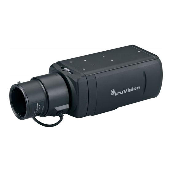
Page 6: Camera Description
Camera description Figure 1: Camera dimensions Figure 2: Side elevation of the camera Bracket mounting holes. Auto iris lens cable. Not included. Can be repositioned to the other Auto iris lens connector. side of the camera. DC-type auto iris lens connection: Camera. - Page 7 Note: Do not attempt to extend the power/data cable connection using RJ45 couplers and Cat5 cable. Only use the data cable connection provided. Note: Use 12 VDC or PoE. Figure 3: Wiring the camera Ethernet RJ45 PoE port Power supply Connect to network devices.
-
Page 8: Accessing The Sdhc Card
Video and log files stored on the SDHC card can only be accessed via the web browser. You cannot access the card using TruVision Navigator or a hybrid DVR. Figure 5: SDHC card slot location in the cameras SDHC card slot... -
Page 9: Mounting The Camera On A Ceiling
Program the camera to suit its location. For further information, please refer to the “TruVision IP Camera Configuration Manual”. Mounting the camera on a ceiling Mount the camera on a ceiling. It is not recommended for mounting on a wall. -
Page 10: Using The Camera With Tvr 60/ Tvn 20/ Tvn 40/ Lnvr And Other Systems
Using the camera with TruVision Navigator A camera must be connected to an Interlogix NVR or hybrid DVR in order to be operated by TruVision Navigator. Please refer to the TruVision Navigator user manual for instructions on operating the camera with the TruVision Navigator. -
Page 11: Pin Definitions
Network Protocols TCP/IP, HTTP, DHCP, DNS, DDNS, RTP/RTSP, PPPoE, SMTP, NTP PoE IEEE 802.3af Miscellaneous Dimensions (L × W × 142 x 68 x 65 mm (5.6 x 2.7 x 2.5 in.) Weight 0.5 kg (1.1 lbs) Operating -10 to +60°C (14 to 140°F) temperature Environmental rating Indoor... - Page 12 Figure 7: Cross-over cable White/Orange White/Orange Orange Orange White-Green White-Green Blue Blue White/Blue White/Blue Green Green White/Brown White/Brown Brown Brown Please make sure your connected cables have the same pin assignment and color as above before deploying the cables in your network. EN 12 Installation Manual...