Alcatel-Lucent OmniSwitch 6350 Hardware User's Manual
Hide thumbs
Also See for OmniSwitch 6350:
- Hardware user's manual (136 pages) ,
- Management manual (366 pages) ,
- Owner's manual (36 pages)

Related Manuals for Alcatel-Lucent OmniSwitch 6350


Summary of Contents for Alcatel-Lucent OmniSwitch 6350
- Page 1 Part No. 060406-10, Rev. E April 2017 OmniSwitch 6350 Hardware Users Guide enterprise.alcatel-lucent.com...
- Page 2 This user guide documents OmniSwitch 6350 hardware, including chassis and associated components. The specifications described in this guide are subject to change without notice. enterprise.alcatel-lucent.com Alcatel-Lucent and the Alcatel-Lucent Enterprise logo are trademarks of Alcatel-Lucent. To view other trademarks used by affiliated companies of ALE Holding, visit: enterprise.alcatel-lucent.com/trademarks.
-
Page 3: Table Of Contents
Chapter 1 OmniSwitch 6350 Switches ..................1-1 Chassis Configurations ....................1-1 10-Port Models ......................1-1 24-Port Models ......................1-1 48-Port Models ......................1-1 OmniSwitch 6350 Feature Overview ................1-2 Security Features ......................1-2 Availability Features ....................1-2 Software Rollback .....................1-2 Hot Swapping ....................1-2 Hardware Monitoring ..................1-2 Chapter 2 Getting Started ...................... - Page 4 OmniSwitch 6350-P10 Rear Panel ................2-6 OmniSwitch 6350-24 ......................2-8 Chassis Features .......................2-8 Front Panel .......................2-8 OmniSwitch 6350-24 Rear Panel ................2-9 OmniSwitch 6350-24 Internal AC Power Supply ............2-9 OmniSwitch 6350-P24 ....................2-11 Chassis Features .....................2-11 Front Panel ......................2-11 OmniSwitch 6350-P24 Rear Panel .................2-12 OmniSwitch 6350-P24 Internal AC Power Supply ..........2-12...
- Page 5 Viewing PoE Power Supply Status .................5-4 Configuring Power over Ethernet Parameters ..............5-4 Power over Ethernet Defaults ..................5-4 Understanding and Modifying the Default Settings ..........5-4 PoE Class Detection ....................5-5 Setting the PoE Operational Status ..............5-5 OmniSwitch 6350 Hardware Users Guide April 2017...
- Page 6 Monitoring Power over Ethernet via CLI ..............5-10 Chapter 7 Managing OmniSwitch 6350 Stacks ..............6-1 In This Chapter ........................6-1 OmniSwitch 6350 Stacking Specifications ..............6-2 OmniSwitch 6350 Stack Overview .................6-2 OmniSwitch 6350 Stacking/Standalone Mode ...............6-3 Roles Within the Stack ....................6-3 Primary and Secondary Management Modules ............6-3 Primary Management Module Selection ............6-6...
- Page 7 Advertencia de la batería de litio ................A-12 Advertencia sobre la tensión de operación ............A-12 Advertencia sobre la desconexión de la fuente ............. A-12 Advertencia sobre una apropiada conexión a tierra ..........A-13 OmniSwitch 6350 Hardware Users Guide April 2017...
- Page 8 Contents Leer “información importante de seguridad” ............A-13 Advertencia de acceso restringido ................. A-13 Advertencia de pulsera antiestática ............... A-13 Clase de seguridad ....................A-13 viii OmniSwitch 6350 Hardware Users Guide April 2017...
-
Page 9: About This Guide
About This Guide This OmniSwitch 6350 Hardware Users Guide describes your switch hardware components and basic switch hardware procedures. Supported Platforms The information in this guide applies to the following products: OS6350-10 • OS6350-P10 • OS6350-24 • OS6350-P24 • OS6350-48 •... -
Page 10: Who Should Read This Manual
CLI commands that pertain directly to hardware configuration, but it is not intended as a software users guide. There are several OmniSwitch 6350 users guides that focus on switch software configuration. Consult those guides for detailed information and examples for configuring your switch software to operate in a live network environment. -
Page 11: Documentation Roadmap
SNMP, and web-based management. It is recommended that you read this guide before connecting your switch to the network. OmniSwitch 6350 Hardware Users Guide April 2017 page xi... - Page 12 CLI commands supported by the switch. This guide can be consulted anytime during the configuration process to find detailed and specific information on each CLI command. page xii OmniSwitch 6350 Hardware Users Guide April 2017...
-
Page 13: Related Documentation
About This Guide Related Documentation Related Documentation The following are the titles and descriptions of OmniSwitch 6350-related user manuals: OmniSwitch 6350 Hardware Users Guide • Detailed technical specifications and procedures for the OmniSwitch chassis and components. OmniSwitch AOS Release 6 CLI Reference Guide •... -
Page 14: Published / Latest Product Documentation
Additionally, with 24-hour-a-day access to Alcatel-Lucent’s Service and Support web page, you’ll be able to view and update any case (open or closed) that you have reported to Alcatel-Lucent’s technical support, open a new case or access helpful release notes, technical bulletins, and manuals. -
Page 15: Omniswitch 6350 Switches
• ports. The chassis features fanless design and internal AC power. 24-Port Models OmniSwitch 6350-24: Provides 24 10/100/1000 BaseT ports and four (4) fixed SFP ports. The chassis • features fanless design and internal AC power. OmniSwitch 6350-P24: Provides 24 PoE 10/100/1000 PoE ports and four (4) fixed SFP ports. -
Page 16: Omniswitch 6350 Feature Overview
OmniSwitch 6350 Feature Overview OmniSwitch 6350 Switches OmniSwitch 6350 Feature Overview Security Features OmniSwitch 6350 switches offer security features for network access control, policy enforcement and attack containment, enabling fully secure networks and OmniVista Network Management System (NMS) support. Availability Features OmniSwitch 6350 switches incorporate advanced Alcatel-Lucent Operating System (AOS) protocols to ensure high availability for mission critical applications. - Page 17 LEDs, which provide visual status information, are provided on the chassis front panel. LEDs are used to indicate conditions such as hardware and software status, temperature errors, link integrity, data flow, etc. For detailed LED descriptions, refer to Chapter 3, “OmniSwitch 6350 Chassis and Hardware Components.” User-Driven Monitoring User-driven hardware monitoring refers to CLI commands that are entered by the user in order to access the current status of hardware components.
- Page 18 OmniSwitch 6350 Feature Overview OmniSwitch 6350 Switches page 1-4 OmniSwitch 6350 Hardware Users Guide April 2017...
-
Page 19: Chapter 2 Getting Started
Electrical Requirements Note. Alcatel-Lucent switches must be installed by a professional installer. It is the responsibility of the installer to ensure that proper grounding is available and that the installation meets applicable local and national electrical codes. - Page 20 Each switch requires one grounded electrical outlet for each power supply installed in the chassis. • OmniSwitch 6350 switches offer both AC and DC power supply support. • For switches using AC power connections, each supplied AC power cord is 2 meters (approx. 6.5 feet).
- Page 21 It is recommended that installers momentarily ground all copper Ethernet cables (especially in new cable runs) to a suitable and safe earth ground before connecting them to the port. page 2-3 OmniSwitch 6350 Hardware Users Guide April 2017...
-
Page 22: Unpacking And Installing The Switch
To protect your switch components from damage, read all unpacking recommendations and instructions carefully before beginning. Unpack your OmniSwitch 6350 chassis as close as possible to the location where it will be installed. Items Included Your OmniSwitch 6350 includes the following items: OmniSwitch chassis •... -
Page 23: Airflow Considerations
Chassis Top View Note. Clearance is not required at the top and bottom of the chassis. Mounting the Switch For information on mounting OmniSwitch 6350 switches, refer to Chapter 3, “OmniSwitch 6350 Chassis and Hardware Components.” page 2-5... -
Page 24: Connections And Cabling
By default, this connector provides a DCE console connection. Serial Connection Default Settings baud rate 9600 parity none data bits (word size) stop bits For information on modifying these settings, refer to the Switch Management Guide. page 2-6 OmniSwitch 6350 Hardware Users Guide April 2017... -
Page 25: Booting The Switch
Note. If the LEDs do not display as indicated, make sure the boot process is complete. If the LEDs do not display as indicated following a complete boot sequence, contact Alcatel-Lucent Enterprise Customer Support. For information on LED states, refer to “OmniSwitch 6350 LED Status”... -
Page 26: Your First Login Session
Welcome to the Alcatel-Lucent OmniSwitch 6350 Software Version 6.7.1.80.R01 Development, July 08, 2015. Copyright(c), ALE USA Inc., 2015. All Rights reserved. OmniSwitch(TM) is a trademark of Alcatel-Lucent Enterprise registered in the United States Patent and Trademark Office. -> Note. A user account includes a login name, password, and user privileges. Privileges determine whether the user has read or write access to the switch and which commands the user is authorized to execute. -
Page 27: Unlocking Session Types
Your First Login Session Getting Started Unlocking Session Types Security is a key feature on OmniSwitch 6350 switches. As described on page 2-8, when you access the switch for the first time, you must use a direct console port connection. All other session types (Telnet, FTP, WebView, and SNMP) are locked out until they are manually unlocked by the user. -
Page 28: Changing The Login Password
Set the current time for the switch by entering system time, followed by the current time in hh:mm:ss. To set the current date for the switch, enter system date, followed by the current date in mm/dd/yyyy. page 2-10 OmniSwitch 6350 Hardware Users Guide April 2017... -
Page 29: Setting Optional Parameters
To view your current changes, enter show system at the CLI prompt. Saving Your Changes Once you have configured this basic switch information, save your changes by entering write memory at the CLI command prompt. page 2-11 OmniSwitch 6350 Hardware Users Guide April 2017... - Page 30 Your First Login Session Getting Started page 2-12 OmniSwitch 6350 Hardware Users Guide April 2017...
-
Page 31: Chassis Configurations
3 OmniSwitch 6350 Chassis and Hardware Components OmniSwitch 6350 (OS6350) switches are available in the chassis configurations as shown in the table below: OS6350-10 Eight (8) 10/100/1000 BaseT ports; two (2) RJ-45/SFP combo ports; fanless design; internal AC power. OS6350-P10 Eight (8) 10/100/1000 BaseT PoE ports;... -
Page 32: Omniswitch 6350 Chassis And Hardware Components
Ethernet Port Status LEDs Console Port System Status LEDs (2) RJ-45/SFP 10/100/1000 combo ports Combo Port Status LEDs USB Port Refer to “OmniSwitch 6350 LED Status” on page 3-21 for LED status information. page 3-2 OmniSwitch 6350 Hardware Users Guide April 2017... -
Page 33: Omniswitch 6350-10 Rear Panel
OmniSwitch 6350 Chassis and Hardware Components OmniSwitch 6350-10 OmniSwitch 6350-10 Rear Panel Note. The figure shows a pre-production version of the chassis without product, safety, and compliance information labels. All production versions of the chassis have these labels. OmniSwitch 6350-10 Rear Panel... - Page 34 OmniSwitch 6350-10 OmniSwitch 6350 Chassis and Hardware Components OmniSwitch 6350-10 Specifications Input Voltage 100 VAC to 240 VAC, 0.9 A, 50-60 Hz Output Voltage 12 VDC, 2.5 A Max Power 30 W page 3-4 OmniSwitch 6350 Hardware Users Guide April 2017...
-
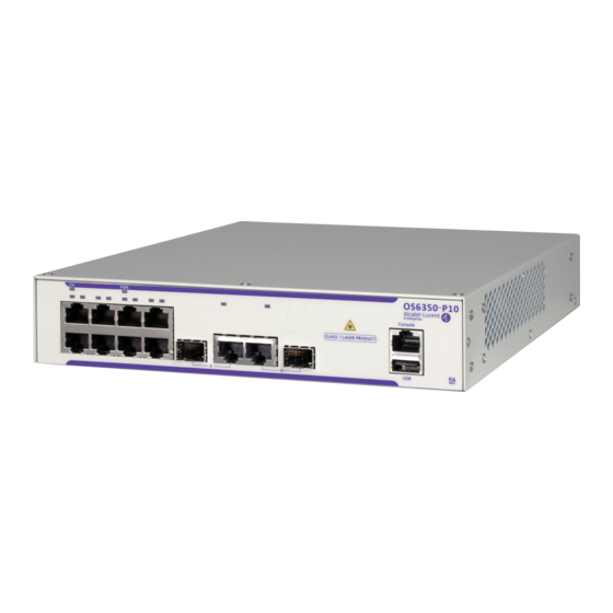
Page 35: Omniswitch 6350-P10
Ethernet Port Status LEDs Console Port System Status LEDs (2) RJ-45/SFP 10/100/1000 combo ports Combo Port Status LEDs USB Port Refer to “OmniSwitch 6350 LED Status” on page 3-21 for LED status information. OmniSwitch 6350 Hardware Users Guide April 2017 page 3-5... -
Page 36: Omniswitch 6350-P10 Rear Panel
OmniSwitch 6350-P10 OmniSwitch 6350 Chassis and Hardware Components OmniSwitch 6350-P10 Rear Panel Note. The figure shows a pre-production version of the chassis without product, safety, and compliance information labels. All production versions of the chassis have these labels. OmniSwitch 6350-P10 Rear Panel... - Page 37 OmniSwitch 6350 Chassis and Hardware Components OmniSwitch 6350-P10 OmniSwitch 6350-P10 Specifications Input Voltage 100 VAC to 240 VAC, 2.2 A, 50-60 Hz Output Voltage 54.5 VDC, 2.5 A Max Power 150 W (30 W System Power; 120 W PoE Power)
-
Page 38: Omniswitch 6350-24
Ethernet Port Status LEDs Console Port System Status LEDs Four (4) Fixed SFP Ports SFP Port Status LEDs USB Port Refer to “OmniSwitch 6350 LED Status” on page 3-21 for LED status information. page 3-8 OmniSwitch 6350 Hardware Users Guide April 2017... -
Page 39: Omniswitch 6350-24 Rear Panel
OmniSwitch 6350 Chassis and Hardware Components OmniSwitch 6350-24 OmniSwitch 6350-24 Rear Panel Note. The figure shows a pre-production version of the chassis without product, safety, and compliance information labels. All production versions of the chassis have these labels. OmniSwitch 6350-24 Rear Panel... - Page 40 OmniSwitch 6350-24 OmniSwitch 6350 Chassis and Hardware Components OS6350-24 Specifications 10/100/1000BaseT ports SFP ports Chassis Width 44.0 cm (17.32 in) Chassis Height 4.4 cm (1.73 in) (1 RU) Chassis Depth 25.2 cm (9.92 in) Weight 4.08 kg (9.0 lb) Operating Humidity...
-
Page 41: Omniswitch 6350-P24
Ethernet Port Status LEDs Console Port System Status LEDs Four (4) Fixed SFP Ports SFP Port Status LEDs USB Port Refer to “OmniSwitch 6350 LED Status” on page 3-21 for LED status information. OmniSwitch 6350 Hardware Users Guide April 2017 page 3-11... -
Page 42: Omniswitch 6350-P24 Rear Panel
OmniSwitch 6350-P24 OmniSwitch 6350 Chassis and Hardware Components OmniSwitch 6350-P24 Rear Panel Note. The figure shows a pre-production version of the chassis without product, safety, and compliance information labels. All production versions of the chassis have these labels. OmniSwitch 6350-P24 Rear Panel... - Page 43 OmniSwitch 6350 Chassis and Hardware Components OmniSwitch 6350-P24 OmniSwitch 6350-P24 Specifications Standard(s) Supported 802.3at 10/100/1000BaseT Power over Ethernet (PoE) Ports SFP ports Chassis Width 44.0 cm (17.32 in) Total Power Budget 525 W System Power Budget 145 W PoE Power Budget...
-
Page 44: Omniswitch 6350-48
Ethernet Port Status LEDs Console Port System Status LEDs Four (4) Fixed SFP Ports SFP Port Status LEDs USB Port Refer to “OmniSwitch 6350 LED Status” on page 3-21 for LED status information. page 3-14 OmniSwitch 6350 Hardware Users Guide April 2017... -
Page 45: Omniswitch 6350-48 Rear Panel
OmniSwitch 6350 Chassis and Hardware Components OmniSwitch 6350-48 OmniSwitch 6350-48 Rear Panel Note. The figure shows a pre-production version of the chassis without product, safety, and compliance information labels. All production versions of the chassis have these labels. OmniSwitch 6350-48 Rear Panel... - Page 46 OmniSwitch 6350-48 OmniSwitch 6350 Chassis and Hardware Components OmniSwitch 6350-48 Specifications 10/100/1000BaseT ports SFP ports Chassis Width 44.0 cm (17.32 in) Chassis Height 4.4 cm (1.73 in) (1 RU) Chassis Depth 25.2 cm (9.92 in) Weight 5.44 kg (12.0 lb)
-
Page 47: Omniswitch 6350-P48
Ethernet Port Status LEDs Console Port System Status LEDs Four (4) Fixed SFP Ports SFP Port Status LEDs USB Port Refer to “OmniSwitch 6350 LED Status” on page 3-21 for LED status information. OmniSwitch 6350 Hardware Users Guide April 2017 page 3-17... -
Page 48: Omniswitch 6350-P48 Rear Panel
OmniSwitch 6350-P48 OmniSwitch 6350 Chassis and Hardware Components OmniSwitch 6350-P48 Rear Panel Note. The figure shows a pre-production version of the chassis without product, safety, and compliance information labels. All production versions of the chassis have these labels. OmniSwitch 6350-P48 Rear Panel... -
Page 49: Omniswitch 6350-P48 Internal Ac Power Supply
OmniSwitch 6350 Chassis and Hardware Components OmniSwitch 6350-P48 OmniSwitch 6350-P48 Internal AC Power Supply P/S Component Description Model OmniSwitch 6350-P48 Nominal Input Voltage 90-220 VAC Maximum Output Power 900 W PoE Power Budget 780 W Output Voltage 12V DC/53V DC... - Page 50 OmniSwitch 6350-P48 OmniSwitch 6350 Chassis and Hardware Components OmniSwitch 6350-P48 Specifications Standard(s) Supported 802.3at 10/100/1000BaseT Power over Ethernet (PoE) Ports SFP ports Chassis Width 44.0 cm (17.32 in) Total Power Budget 900 W System Power Budget 120 W PoE Power Budget...
-
Page 51: Omniswitch 6350 Led Status
OmniSwitch 6350 Chassis and Hardware Components OmniSwitch 6350 LED Status OmniSwitch 6350 LED Status State Description Solid Green The switch has passed hardware diagnostic tests and the system software is operational Blinking Green Normal diagnostics and/or Remote Config Load in progress... -
Page 52: Ac Power Cords
AC Power Cords OmniSwitch 6350 Chassis and Hardware Components AC Power Cords Since the power cord is the switch’s only disconnect device, it should be plugged into an easily accessible outlet. In the event that your power cord is lost or damaged, refer to the specifications below. -
Page 53: Console Port
OmniSwitch 6350 Chassis and Hardware Components Console Port Console Port The console port, located on the chassis front panel, provides a console connection to the switch and is required when logging into the switch for the first time. By default, this RJ-45 connector provides a DTE console connection. -
Page 54: Port Pinouts
Port Pinouts OmniSwitch 6350 Chassis and Hardware Components Port Pinouts RJ-45 Console Port – Connector Pinout Pin Number Signals as DTE Console Port Ground Ground 10/100 Ethernet Port – RJ-45 Pinout (non-PoE) Pin Number Description not used not used not used not used Gigabit Ethernet Port –... -
Page 55: 10/100/1000 Mbps Power Over Ethernet Port - Rj-45 Pinout
OmniSwitch 6350 Chassis and Hardware Components Overtemp Condition 10/100/1000 Mbps Power over Ethernet Port – RJ-45 Pinout Pin Number Description RX+ (-VDC) RX- (-VDC) TX+ (+VDC) TX- (+VDC) Overtemp Condition The OmniSwitch is designed to operate within a specified operating temperature as noted under the specifications section. - Page 56 Overtemp Condition OmniSwitch 6350 Chassis and Hardware Components page 3-26 OmniSwitch 6350 Hardware Users Guide April 2017...
-
Page 57: Mounting Omniswitch 6350 Switches
4 Mounting OmniSwitch 6350 Switches This chapter covers different mounting and installation options. OmniSwitch 6350 switches may be either table- or rack-mounted. Anti-Static Warning. Before handling any components, free yourself of static by wearing a grounding strap or by grounding yourself properly. Static discharge can damage the switch and related components. -
Page 58: General Installation Recommendations
Note. Clearance is not required at the top and bottom of the chassis. Clearance recommendations at the front and rear of chassis are for access to cabling and components only and are not intended as a specific airflow requirement. page 4-2 OmniSwitch 6350 Hardware Users Guide April 2017... - Page 59 If installed in a closed or multi-unit rack assembly, the operating ambient temperature of the rack environment may be greater than room ambient. Therefore, consideration should be given to installing the equipment in an environment compatible with the maximum ambient temperature (Tma) specified by the manufacturer. OmniSwitch 6350 Hardware Users Guide April 2017 page 4-3...
-
Page 60: Mechanical Loading
(e.g. use of power strips). General Table-Mounting Guidelines OmniSwitch 6350 switches can be installed freestanding as tabletop-mounted units. If you will be table- mounting your switch(es), refer to the important guidelines below before installing. -
Page 61: Rack-Mounting
The chassis has rack-mount flanges that support standard 19-inch rack mount installations. • Alcatel-Lucent does not provide rack-mount screws. Use the screws supplied by the rack vendor. • To prevent a rack from becoming top heavy, it is recommended that you install the switch at the •... - Page 62 Clip in “In” (engaged) position “CLICK” Secure the flange to the chassis using the attachment screw (provided). Repeat steps 1 through 4 for the flange on the opposite side of the chassis. page 4-6 OmniSwitch 6350 Hardware Users Guide April 2017...
-
Page 63: Installing The Chassis In The Rack
Once the holes are aligned, the second person should insert a screw through the bottom hole on each flange. Tighten both screws until they are secure. Install the remaining screws in the top hole of each flange. Be sure that all screws are securely tightened. OmniSwitch 6350 Hardware Users Guide April 2017 page 4-7... -
Page 64: Connecting The Chassis To A Power Source
Follow the steps below to power on the chassis using and AC power source: Connect the IEC-60320-C15 end of the supplied power cord to the chassis. Connect power supply to AC power source. Monitor the chassis as it boots. page 4-8 OmniSwitch 6350 Hardware Users Guide April 2017... -
Page 65: Booting An Omniswitch
Note. If the LEDs do not display as indicated, make sure the boot process is complete. If the LEDs do not display as indicated following a complete boot sequence, contact Alcatel-Lucent Customer Support. For information on LED states, refer to “OmniSwitch 6350 LED Status”... -
Page 66: Console Port
To change the data bits (i.e., word size) value, enter boot serialwordsize, followed by the number of data bits. Options include 7 and 8 (default). For example: Boot > boot serialwordsize 7 page 5-2 OmniSwitch 6350 Hardware Users Guide April 2017... - Page 67 To save changes to the boot.params file, refer to step 7. Return to the CLI prompt by entering exit at the boot prompt. OmniSwitch 6350 Hardware Users Guide April 2017...
-
Page 68: Monitoring The Chassis
Temperature Status = UNDER THRESHOLD, Temperature Danger Threshold (deg C) = 85 For a complete list of output definitions for this command, refer to the OmniSwitch AOS Release 6 CLI Reference Guide. page 5-4 OmniSwitch 6350 Hardware Users Guide April 2017... -
Page 69: Viewing The Power Supply Status
The front and rear panel of provides status LEDs that are useful in visually monitoring the status of the switches. LEDs include: Ethernet Port LEDs • System Status LEDs • For tables showing LED states operating normally, refer to “OmniSwitch 6350 LED Status” on page 3-21. OmniSwitch 6350 Hardware Users Guide April 2017 page 5-5... - Page 70 Monitoring the Chassis Booting OmniSwitch 6350 Switches page 5-6 OmniSwitch 6350 Hardware Users Guide April 2017...
-
Page 71: Managing Power Over Ethernet (Poe)
6 Managing Power over Ethernet (PoE) Power over Ethernet (PoE) is supported on OmniSwitch 6350 switches and provides inline power directly from the switch’s Ethernet ports. Powered Devices (PDs) such as IP phones and wireless APs can be powered directly from the switch’s RJ-45 ports. -
Page 72: In This Chapter
Note. You can also monitor all chassis components and manage many chassis features, including Power over Ethernet, with WebView, Alcatel-Lucent’s embedded web-based device management application. WebView is an interactive and easy-to-use GUI that can be launched from the OmniVista or a web browser. -
Page 73: Power Over Ethernet Specifications
Managing Power over Ethernet (PoE) Power over Ethernet Specifications Power over Ethernet Specifications The table below lists general specifications for Alcatel-Lucent’s Power over Ethernet support. For more detailed power supply and Power Source Equipment (PSE) specifications, refer to Chapter 3, “OmniSwitch 6350 Chassis and Hardware Components.”... -
Page 74: Viewing Poe Power Supply Status
OmniSwitch AOS Release 6 CLI Reference Guide. Note. PoE units support different wattage power supplies. If an unsupported power supply is used, a console message and a trap are generated. page 6-4 OmniSwitch 6350 Hardware Users Guide April 2017... -
Page 75: Poe Class Detection
To disable PoE on a specific PoE-capable port, enter a slot/port number. For example: -> lanpower stop 1/4 To disable PoE for all PoE-capable in a slot, enter the corresponding slot number only. For example: -> lanpower stop 1 OmniSwitch 6350 Hardware Users Guide April 2017 page 6-5... -
Page 76: Configuring The Total Power Available To A Port
These settings are only used for configuring a maximum amount of power that may be used, any unused power is still available and remains a part of the overall PoE budget. page 6-6 OmniSwitch 6350 Hardware Users Guide April 2017... -
Page 77: Setting Port Priority Levels
1 to the highest priority level of critical. Now that the default value has been reconfigured, this port should be reserved for those PDs that are mission critical for network operations. OmniSwitch 6350 Hardware Users Guide April 2017 page 6-7... -
Page 78: Understanding Priority Disconnect
To enable priority disconnect, use the lanpower priority-disconnect command. Be sure to specify the slot number in the command line. For example, the syntax -> lanpower 1 priority-disconnect enable enables priority disconnect on slot 1. page 6-8 OmniSwitch 6350 Hardware Users Guide April 2017... -
Page 79: Priority Disconnect Is Enabled; Same Priority Level On All Pd
When a PD is being connected to a port with a lower priority level than all other in the slot, the incoming PD will be denied power, regardless of its physical port number. Devices connected to other higher- priority will continue operating without interruption. OmniSwitch 6350 Hardware Users Guide April 2017 page 6-9... -
Page 80: Priority Disconnect Is Disabled
31000 Undefined None Slot 1 Max Watts 225 1 Power Supplies Available Note. For detailed information on show lanpower command output, refer to the OmniSwitch AOS Release 6 CLI Reference Guide. page 6-10 OmniSwitch 6350 Hardware Users Guide April 2017... -
Page 81: Managing Omniswitch 6350 Stacks
7 Managing OmniSwitch 6350 Stacks In addition to their working as individual stand-alone switches OmniSwitch 6350 switches can also be linked together to work as a single virtual chassis known as a stack. With stacks, users can easily expand their switching capacity simply by adding additional switches to the stack. In addition, stacks provide enhanced resiliency and redundancy features. -
Page 82: Omniswitch 6350 Stacking Specifications
OS6350-48/P48 switches, ports 49 and 50 are both uplink (1Gbps) and stacking capable (5Gbps) ports. OmniSwitch 6350 Stack Overview Users can configure OmniSwitch 6350 switches into a single virtual chassis known as a stack. With stacks, switching capacity can be easily expanded simply by adding additional switches to the stack. For example, a user can start with a stack composed of two switches and add additional switches to that stack as network demands increase over time. -
Page 83: Omniswitch 6350 Stacking/Standalone Mode
The switch must be rebooted for the new mode to take affect. Roles Within the Stack In order to operate as a virtual chassis, switches within an OmniSwitch 6350 stack are assigned specific roles. These roles include primary and secondary management roles, idle status, and pass-through. For detailed descriptions of each of these roles, including their practical functions within the virtual chassis, refer to the sections below. - Page 84 Refer to “Synchronizing Switches in a Stack” on page 7-36 more information. Primary A stack of four OmniSwitch 6350 switches is Secondary operating normally. The stack consists of a pri- mary module, secondary module, and two ele- Idle ments operating in idle status.
- Page 85 Managing OmniSwitch 6350 Stacks Roles Within the Stack A stack of two OmniSwitch 6350 switches is operating normally. The stack consists of a pri- Primary mary module and a secondary module. (The Secondary software on both elements in the stack is syn- chronized.)
-
Page 86: Primary Management Module Selection
Managing OmniSwitch 6350 Stacks Primary Management Module Selection For a stack of OmniSwitch 6350 switches to operate as a virtual chassis, there must be a mechanism for dynamically selecting the switch within the stack that will assume the primary management role. - Page 87 For more information on using saved slot information to determine the primary switch in a stack, refer to the diagram below: Saved Slot 6 Four OmniSwitch 6350 switches are stacked; all Saved Slot 5 switches are connected via stacking cables. The user...
- Page 88 For more information on using saved slot information to determine the primary switch in a stack, refer to the diagram below: Four OmniSwitch 6350 switches are stacked and connected via stacking cables. All switches are currently powered off. The user powers on a single switch in the stack. In this case, the bottom-most switch is powered on.
-
Page 89: Secondary Management Module Selection
Roles Within the Stack Secondary Management Module Selection In order to provide effective management module redundancy, all OmniSwitch 6350 stacked configurations dynamically assign a backup, or secondary, management module during the boot process. OmniSwitch 6350 stacks use two different methods for selecting the secondary switch. - Page 90 For more information on using saved slot information to determine the secondary management module in a stack, refer to the diagram below: Saved Slot 1 Four OmniSwitch 6350 switches are stacked; all Saved Slot 3 switches are connected via stacking cables. The user...
-
Page 91: Idle Module Role
For more information on dynamic assignment of idle modules in a stack, refer to the diagram below: Four OmniSwitch 6350 switches are stacked; all switches are connected via stacking cables. The stack is booted. -
Page 92: Pass-Through Mode
MAC address will be given the secondary management role. The slot with the higher MAC address will be forced into the pass-through mode. page 7-12 OmniSwitch 6350 Hardware Users Guide April 2017... -
Page 93: Recovering From Pass-Through Mode (Duplicate Slot Numbers)
1 through 8, respectively. For example, if a module enters pass-through and has the slot number 1004, the LED for the module blinks the number 4. For more information on the slot indicator LED, refer “OmniSwitch 6350 LED Status” on page 3-21. - Page 94 State Saved Link A Remote Remote Link B Remote Remote Slot State Port State Port ----+-----------+--------+------+-------+-------+-------+-------+-------+------- 1 PRIMARY RUNNING StackA StackA 2 SECONDARY RUNNING StackB StackB 3 IDLE RUNNING StackA StackB page 7-14 OmniSwitch 6350 Hardware Users Guide April 2017...
- Page 95 StackA 3 IDLE RUNNING StackB StackA 4 IDLE RUNNING StackB StackA 5 IDLE RUNNING StackB StackA 6 IDLE RUNNING StackB StackA 7 IDLE RUNNING StackB StackA 8 IDLE RUNNING StackB StackA OmniSwitch 6350 Hardware Users Guide April 2017 page 7-15...
-
Page 96: Stack Cabling
Stacking cables for OmniSwitch 6350 switches must be connected in an A-B pattern. In other words, the cable connected to stacking port A of one switch must be connected to stacking port B of the adjacent switch. -
Page 97: Redundant Stacking Cable Connection
Managing OmniSwitch 6350 Stacks Stack Cabling Redundant Stacking Cable Connection OmniSwitch 6350 switches allow redundant stacking cable connections between the top-most and bottom- most switches in a stack. Note. For a stacked configuration to have effective redundancy, a redundant stacking cable must be installed between the upper-most and bottom-most switch in the chassis at all times. -
Page 98: Checking Redundant Stacking Cable Status
For example: Redundant cable status : present Tokens used Tokens available : 31 In this example, a redundant stacking cable connection is present between the top-most and bottom-most switches in the stack. page 7-18 OmniSwitch 6350 Hardware Users Guide April 2017... -
Page 99: Slot Numbering
Slot Numbering Slot Numbering For a stack of OmniSwitch 6350 switches to operate as a virtual chassis, each module in the stack must be assigned a unique slot number. To view the current slot assignments for a stack, use the... -
Page 100: Dynamic Slot Number Assignment
4, and so on. When the bottom of the stack is reached, the slot numbering sequence resumes at the top of the stack, as shown. This helps ensure a more ordered and manageable stack topology. Dynamic Slot Numbering Example 1 page 7-20 OmniSwitch 6350 Hardware Users Guide April 2017... - Page 101 3 is assigned the slot number 4, and so on. This default procedure ensures the most ordered and manageable stack topology out of the box. Dynamic Slot Numbering Example 2 OmniSwitch 6350 Hardware Users Guide April 2017 page 7-21...
-
Page 102: Manual Slot Number Assignment
Instead, new slot number information is first saved to each boot.slot.cfg file across the stack. The reboot is saved for last in order to avoid duplicate slot numbers within the stack, which would cause unwanted pass-though mode conditions (see page 7-12). page 7-22 OmniSwitch 6350 Hardware Users Guide April 2017... -
Page 103: Reverting To The Dynamic Slot Numbering Model
Because the system software no longer has preassigned slot information to read during the boot process, the stack uses the dynamic slot number assignment method described on page 7-20. OmniSwitch 6350 Hardware Users Guide April 2017 page 7-23... -
Page 104: Hot-Swapping Modules In A Stack
Managing OmniSwitch 6350 Stacks Hot-Swapping Modules In a Stack As with chassis-based switches, NI modules within an OmniSwitch 6350 virtual chassis are hot- swappable. NI modules are essentially those modules operating in the stack in idle mode. These modules can be removed from, or added to, an existing stack without disrupting other modules in the stack. -
Page 105: Merging Stacks
For information on stack cabling, refer to page 7-16. Power on all incoming modules. Note. No more than eight switches can operate in a single stacked configuration at any time. OmniSwitch 6350 Hardware Users Guide April 2017 page 7-25... -
Page 106: Reloading Switches
OmniSwitch AOS Release 6 CLI Reference Guide. Primary - Slot 1 In this stack of four OmniSwitch 6350 switches, the slot Secondary - Slot 2 1 switch is the primary management module. The slot 2 switch is the secondary. - Page 107 If there are only two switches in the stack, the switch that was reloaded (the former primary) assumes the secondary role when it comes back up. In this stack of two OmniSwitch 6350 switches, the slot Primary - Slot 1 1 switch is the primary management module.
-
Page 108: Reloading The Secondary Management Module
OmniSwitch AOS Release 6 CLI Reference Guide. Primary - Slot 1 In this stack of four OmniSwitch 6350 switches, the slot Secondary - Slot 2 1 switch is the primary management module. The slot 2 switch is the secondary. - Page 109 If there are only two switches in the stack, the switch that was reloaded (the former secondary) resumes the secondary role when it comes back up. In this stack of two OmniSwitch 6350 switches, the slot Primary - Slot 1 1 switch is the primary management module.
-
Page 110: Reloading Switches With Idle Roles
Otherwise, the switch is likely to come up again in pass-through mode. For detailed information, including steps used to recover from pass-through, refer to page 7-12. page 7-30 OmniSwitch 6350 Hardware Users Guide April 2017... -
Page 111: Reloading All Switches In A Stack
All other switches will be assigned to idle roles. An illustrated example of this method for assigning slot numbers and management roles is provided on pages 7-22 and 7-23. OmniSwitch 6350 Hardware Users Guide April 2017 page 7-31... - Page 112 To check the current saved slot information across the stack, use the show stack topology command. For detailed information on pass-through mode, refer to “Pass-Through Mode” on page 7-12. page 7-32 OmniSwitch 6350 Hardware Users Guide April 2017...
-
Page 113: Avoiding Split Stacks
For more information on the redundant stacking cable connection, refer to page 7-17. OmniSwitch 6350 Hardware Users Guide April 2017 page 7-33... -
Page 114: Changing The Secondary Module To Primary
Managing OmniSwitch 6350 Stacks Changing the Secondary Module to Primary OmniSwitch 6350 stacks allow users to manually force the secondary switch to assume the primary management role. This is referred to as “takeover.” The behavior of a takeover is similar to that of... - Page 115 If there are only two switches in the stack, the former primary switch resumes the secondary role when it comes back up following the takeover. In this stack of two OmniSwitch 6350 switches, the slot Primary - Slot 1 1 switch is the primary management module. The slot 2 Secondary - Slot 2 switch is the secondary.
-
Page 116: Synchronizing Switches In A Stack
Note. For more information on management module synchronization and managing the /flash/working and /flash/certified directories, refer to the “Managing CMM Directory Content” chapter in the OmniSwitch AOS Release 6 Switch Management Guide. page 7-36 OmniSwitch 6350 Hardware Users Guide April 2017... -
Page 117: Stack Split Detection (Ssp)
MAC and IP addresses and network disruption. Guard Timer - A configurable timer determining how long a unit will wait before beginning to send • SSP PDUs after a stack recovery. OmniSwitch 6350 Hardware Users Guide April 2017 page 7-37... -
Page 118: Basic Operation
After the re-boot the administrator has to manually recover the switch by first disabling SSP and then re-enabling SSP. This clears the protection state variables stored in the EEPROM/boot.params. page 7-38 OmniSwitch 6350 Hardware Users Guide April 2017... - Page 119 3. Automatic Recovery - After guard-timer expiration, Primary will bring up elements one at a time. 4. Once stack is functioning, Primary will send trap indicating stack recovery. Stack Split Example OmniSwitch 6350 Hardware Users Guide April 2017 page 7-39...
-
Page 120: Monitoring The Stack
Visually Monitoring the Stack Users can also monitor many stack operations by viewing the front panel LEDs on all elements in the stack. Refer to “OmniSwitch 6350 LED Status” on page 3-21 for detailed information on LEDs and stack status. -
Page 121: Cli Commands Supported On Both Primary And Secondary Management Modules
Memory Monitoring Commands show log pmd OmniSwitch 6350 Hardware Users Guide April 2017 page 7-41... - Page 122 Monitoring the Stack Managing OmniSwitch 6350 Stacks page 7-42 OmniSwitch 6350 Hardware Users Guide April 2017...
- Page 123 Telekommunikationsendeinrichtungen, falls zutreffend). Español: Este equipo cumple los requisitos esenciales y otras disposiciones de las directivas 2004/108/CE (EMC), 2006/95/CE (LVD), 91/263/CEE (equipos terminales de telecomunicación, si procede), 1999/5/ CE (R&TTE, si procede). OmniSwitch 6350 Hardware Users Guide April 2017 page A-1...
-
Page 124: Appendix A Regulatory Compliance And Safety Information
WARNING: This product contains chemicals known to the State of California to cause cancer and birth defects or other reproductive harm. Products are packaged using one or more of the following packaging materials: Corrugated Cardboard Corrugated Fiberboard Low-Density Polyethylene page A-2 OmniSwitch 6350 Hardware Users Guide April 2017... -
Page 125: Waste Electrical And Electronic Equipment (Weee) Statement
Switzerland and therefore marked with the symbol: Treatment applied at end of life of the product in these countries shall comply with the applicable national laws implementing directive 2002/96EC on waste electrical and electronic equipment (WEEE). OmniSwitch 6350 Hardware Users Guide April 2017 page A-3... -
Page 126: Standards Compliance
• EN 61000-4-8 • EN 61000-4-11 • Environmental Standards ETS 300 019 Storage Class 1.1 • ETS 300 019 Transportation Class 2.3 • ETS 300 019 Stationary Use Class 3.1 • page A-4 OmniSwitch 6350 Hardware Users Guide April 2017... -
Page 127: Canada Class A Statement
CISPR22 Class A Warning This is a Class A product. In a domestic environment, this product may cause radio interference. Under such circumstances, the user may be requested to take appropriate countermeasures. OmniSwitch 6350 Hardware Users Guide April 2017 page A-5... -
Page 128: Korea Emissions Statement
This is a Class A Information Product. When used in a residential environment, it may cause radio frequency interference. Under such circumstances, the user may be requested to take appropriate counter- measure. page A-6 OmniSwitch 6350 Hardware Users Guide April 2017... -
Page 129: Network Cable Installation Warning
Installationen, Wartungen oder Konfigurationen vorge- nommen werden. Español: Para evitar peligro de descargas, no conecte o desconecte ningun cable, ni realice ninguna insta- lación, maintenimiento o reconfiguración de este producto durante una tormenta eléctrica. OmniSwitch 6350 Hardware Users Guide April 2017 page A-7... -
Page 130: Installation Warning
Netzverbindungen getrennt sind bevor das Gerät gewartet oder bewegt wird. Español: Antes de empezar a trabajar con un sistema, asegurese que el interruptor está cerrado y el cable eléctrico desconectado. page A-8 OmniSwitch 6350 Hardware Users Guide April 2017... -
Page 131: Proper Earthing Requirement Warning
• toma de alimentación adecuadamente cableada y con toma de tierra. Cualquier otro equipo a cual se conecte este producto también debe estar conectado a tomas de • alimentación adecuadamente cableadas. OmniSwitch 6350 Hardware Users Guide April 2017 page A-9... -
Page 132: Read Important Safety Information Warning
Español: Este equipo se debe instalar en un sitio con acceso restrinjido. Un sitio con el acceso restrinjido es uno seguro y con acceso limitado al personal de servicio que tiene una clave especial u otros medios de seguridad. page A-10 OmniSwitch 6350 Hardware Users Guide April 2017... -
Page 133: Wrist Strap Warning
Français: L'électricité statique (ESD) peut endommager les composants du commutateur. Pour cette raison Alcatel-Lucent joint à l'envoi du châssis un bracelet antistatique à brancher sur la prise mise à la terre située en bas à droite du commutateur. Vous devrez mettre ce bracelet avant toute intervention hard- ware. -
Page 134: Instrucciones De Seguridad En Español
Deseche las baterías usadas según las instrucciones del fabricante. Las instrucciones del fabricante son como sigue: Devuelva el módulo con la batería del litio a Alcatel-Lucent. La batería del litio será substitu- ida en la fábrica de Alcatel-Lucent. -
Page 135: Advertencia Sobre Una Apropiada Conexión A Tierra
Para que la pulsera antiestática sea eficaz en la eliminación de ESD, las fuentes de alimentación se deben instalar en el chasis y enchufar en las salidas de CA con descarga a tierra. Clase de seguridad Cumple con 21CFR 1040.10 y 1040.11 ó sus equivalentes. OmniSwitch 6350 Hardware Users Guide April 2017 page A-13... - Page 136 Instrucciones de seguridad en español Regulatory Compliance and Safety Information page A-14 OmniSwitch 6350 Hardware Users Guide April 2017...