Cisco IE 4010 Hardware Installation Manual
Hide thumbs
Also See for IE 4010:
- Software configuration manual (1066 pages) ,
- Product documentation (28 pages) ,
- Hardware installation manual (86 pages)

Related Manuals for Cisco IE 4010


Summary of Contents for Cisco IE 4010
- Page 1 Cisco IE 4010 Switch Hardware Installation Guide First Published: September 2016 Last Updated: September 2016 Cisco Systems, Inc. www.cisco.com...
- Page 2 ■ Consult the dealer or an experienced radio/TV technician for help. Modifications to this product not authorized by Cisco could void the FCC approval and negate your authority to operate the product. The Cisco implementation of TCP header compression is an adaptation of a program developed by the University of California, Berkeley (UCB) as part of UCB’s public domain version of the UNIX operating system.
-
Page 3: Related Publications
Statement 1071 The safety warnings for this product are translated into several languages in the Cisco IE 4010 Switch Product Document of Compliance that ships with the product. The EMC regulatory statements are also included in that guide. - Page 4 For information on obtaining documentation, obtaining support, providing documentation feedback, security guidelines, and also recommended aliases and general Cisco documents, see the monthly What’s New in Cisco Product Documentation, which also lists all new and revised Cisco technical documentation, at:...
-
Page 5: Product Overview
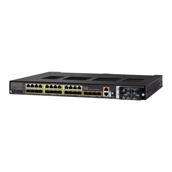
Product Overview The Cisco IE 4010 switch provides a rugged and secure switching infrastructure for harsh environments. It is suitable for industrial Ethernet applications, including process manufacturing, utility substations, intelligent transportation systems (ITSs), rail transportation, and other similar deployments. In industrial environments, you can connect the switch to any Ethernet-enabled industrial communication devices, including programmable logic controllers (PLCs), human-machine interfaces (HMIs), drives, sensors, and input and output (IO) devices. -
Page 6: Cable Side
Statement 1072 The 10/100/1000 PoE ports on the Cisco IE-4010 switches provide PoE support for devices that are compliant with IEEE 802.3af/802.3at. The Cisco prestandard PoE is also supported for Cisco IP Phones and Cisco Aironet Access Points. The PoE ports on the switch deliver up to 30 W of PoE+ power. -
Page 7: Alarm Ports
The 100BASE-TX and 1000BASE-T traffic requires CA5, CAT5e, or CAT6 unshielded twisted pair (UTP) cable. The 10BASE-T traffic can use CAT3 or CAT4 UTP cable. For information about configuring and monitoring PoE ports, see the switch software configuration guide on Cisco.com. For information about port connections and port specifications, see... -
Page 8: Sd Flash Memory Card
The switch Ethernet SFP modules provide connections to other devices. These field-replaceable transceiver modules provide the interfaces. The IE 4010 supports both FE and GE optics. SFP modules have local connectors (LCs) for fiber-optic connections or RJ-45 connectors for copper connections. - Page 9 The USB console interface speeds are the same as the RJ-45 console interface speeds. To use the USB console port, you must install the Cisco Windows USB device driver on the device that is connected to the USB console port (device running with Microsoft Windows). See...
-
Page 10: Switch Panel Leds
Product Overview Cable Side Switch Panel LEDs Figure 4 Switch LEDs (Cable Side) Port Status LEDs 1-28 Port speed status Express Setup button Port duplex status SYS (system) Redundancy status USB (mini-USB console) Synchronous Ethernet status SD (SD flash memory card) Alarm Status (1 to 4 and Output). - Page 11 Product Overview Cable Side Table 2 Port Mode LEDs Mode LED Port Mode Description All Off Port status The port status. This is the default mode. SPEED Port speed The port operating speed: 10, 100, 1000 mbps or 10 Gbps. DUPLX Port duplex mode The port duplex mode: full duplex or half duplex.
- Page 12 PoE/PoE+ is on but one of the high priority ports power is disconnected or failed. PoE+ faults occur when noncompliant cabling or powered devices are connected to a PoE+ port. Use only standard-compliant cabling to connect Cisco prestandard IP Phones and wireless access points or IEEE 802.3af/at-compliant devices to PoE+ ports.
-
Page 13: Alarm Leds
Product Overview Cable Side Alarm LEDs Table 5 Alarm LEDs Color System Status 1-4 Input Alarms Green Alarm not present Minor alarm present Blinking red Major alarm present Output Alarm Green Alarm not present Alarm condition present SD Flash Memory Card LED Table 6 SD Flash Card LED Color... -
Page 14: System Led
Product Overview Power-Supply Side System LED Table 8 System LED Color System Status System is not powered on. Blinking green Power-On Self-Test (POST) is in progress. Green System is operating normally. System is receiving power but is not functioning properly. Power-Supply Side The power-supply side has the LED panel and two power-supply slots for the removable power supplies. -
Page 15: Power Supply Features
For more information about these LEDs, see Switch Panel LEDs, page Power Supply Features The switch has two slots for power-supply modules: PWR-RGD-LOW-DC-H: low-voltage DC PWR-RGD-AC-DC-H: high-voltage AC or DC Note: For detailed specifications, see the IE 4010 Data Sheet. -
Page 16: Management Options
Cisco IOS CLI You can configure and monitor the switch from the CLI. Connect your management station to the switch console port or use Telnet from a remote management station. See the switch command reference on Cisco.com for information. ... -
Page 17: Table Of Contents
Connecting Devices to the Ethernet Ports, page 31 Where to Go Next, page 32 Warnings These warnings are translated into several languages in the Regulatory Compliance and Safety Information for the Cisco IE 4010 Switch document. These warning statements apply to all the switches: Warning: Before working on equipment that is connected to power lines, remove jewelry (including rings, necklaces, and watches). -
Page 18: Installation Guidelines
SYS LED turns green. The other LEDs turn off and return to their operating status. If the switch fails POST, the SYS LED is amber. Note: Contact Cisco Systems immediately if your switch fails POST. After a successful POST, disconnect the power from the switch. For more information, see Wiring the Power Source, page 39. -
Page 19: Installing The Switch
Switch Installation Installing the Switch Installing the Switch Rack-Mounting, page 15 Wall-Mounting, page 22 Rack-Mounting To rack-mount the switch, select the rack size and follow the steps in these sections: Attaching Brackets for 19-Inch Racks, page 15 ... - Page 20 Switch Installation Installing the Switch Figure 7 Attaching Brackets for 19-Inch Racks (Front bracket) Figure 8 Attaching Brackets for 19-Inch Racks (Mid Mount)
- Page 21 Switch Installation Installing the Switch Figure 9 Attaching Brackets for 19-Inch Racks (Rear Mount) Attaching Brackets for 19-Inch Racks for IP-30 Compliance (Optional) Before installing the mounting brackets, you need to install the rubber plugs in the unused mounting holes. Figure 10 on page 18 shows a close-up of the rubber plug.
- Page 22 Switch Installation Installing the Switch Figure 10 Inserting the Rubber Plug Rubber plug Screwdriver Switch Identify your bracket mounting position. See Attaching Brackets for 19-Inch Racks, page Insert the rubber plugs in the appropriate holes on both sides of the switch. See Figure 11 on page Use a screwdriver or pen to completely push in the rubber plugs.
- Page 23 Switch Installation Installing the Switch Figure 11 Plug locations by position Note: For IP-30 compliance: If you use 23-inch brackets or ETSI brackets, you can insert the rubber plugs in the same holes as shown in Figure 11 on page 19 before installing the brackets.
- Page 24 Switch Installation Installing the Switch Attaching Brackets for 23-Inch Racks If 23-inch brackets (RM-RGD-23IN=) are required, follow steps in Figure 12 on page 20 for installation. Note: 23-inch and ETSI brackets should not be used in high vibration environments, including any railway application (EN50155).
-
Page 25: Attaching Brackets For Etsi Racks
Switch Installation Installing the Switch Attaching Brackets for ETSI Racks Figure 13 Attaching Brackets (RM-RGD-ETSI=) for ETSI Racks C i sco C G S 25 20 C i sco C G S 25 20 Phillips flat-head screws Power-supply-side mounting position Cable-side-mounting position Note: 23-inch and ETSI brackets should not be used in high vibration environments, including any railway application... - Page 26 Switch Installation Installing the Switch Figure 14 Rack-Mounting After the switch is mounted in the rack: Wire the switch to a power source. See Wiring the Power Source, page Connect the ports. See Connecting Devices to the Ethernet Ports, page Attach the cable guide to prevent the cables from obscuring the LED panels on the devices in the rack.
- Page 27 Switch Installation Installing the Switch Base side (facing wall): 0 in. (0 cm) Attaching Brackets Figure 15 Attaching 19-inch Rack Brackets Phillips truss-head screws...
- Page 28 For the best support of the switch and cables, ensure that the switch is attached securely to wall studs or to a firmly attached plywood mounting backboard. Orientation should exactly match the figure below, with power terminal down, the LEDs up, and the venting and Cisco Logo facing away from the wall. See...
- Page 29 Switch Installation Installing the Switch Figure 16 Wall-Mounting User-supplied screws After the Switch is Mounted on the Wall Wire the switch to a power source. See Wiring the Power Source, page For configuration instructions about using the CLI setup program, go to Configuring the Switch with the CLI Setup Program, page ...
-
Page 30: Installing And Removing Sfp Modules
You can use any combination of rugged SFP modules. Each SFP module must be of the same type as the SFP module on the other end of the cable, and the cable must not exceed the stipulated cable length for reliable communications. For more information about SFP modules, see Cisco Transceiver Modules. Caution: Depending on the SFP module you use, the operating temperature limits may be effected. - Page 31 Switch Installation Installing and Removing SFP Modules Figure 17 Installing an SFP Module C i s c o IE 3 0 1 0 Caution: Do not remove the dust plugs from the fiber-optic SFP module port or the rubber caps from the fiber-optic cable until you are ready to connect the cable.
- Page 32 Position the SFP transceiver in front of the port socket opening. Note: Different Cisco devices have different SFP transceiver socket configurations. Your Cisco device might require that the SFP transceiver be installed with the bale-clasp either in a latch-up or a latch-down orientation. Verify that you have the SFP transceiver oriented correctly when you position it in front of the port socket.
-
Page 33: Connecting To Sfp Modules
Switch Installation Installing and Removing SFP Modules Connecting to SFP Modules This section describes how to connect to a fiber-optic or 1000BASE-T SFP port. For instructions on how to install or remove an SFP module, see Connecting Devices to the Ethernet Ports, page Warning: Class 1 laser product. -
Page 34: Replacing The Sd Flash Memory Card
Switch Installation Replacing the SD Flash Memory Card Insert the other cable end in an RJ-45 connector on a target device. Observe the port status LED. — The LED turns green when the switch and the target device have an established link. —... -
Page 35: Connecting Devices To The Ethernet Ports
Therefore, you can use either a crossover or a straight-through cable for connections to a Ethernet port, regardless of the type of connected device. See the switch software configuration guide or the switch command reference on Cisco.com for more information about autonegotiation and auto-MDIX. -
Page 36: Where To Go Next
Switch Installation Where to Go Next Caution: Category 5e and Category 6 cables can store high levels of static electricity. Always ground the cables to a suitable and safe earth ground before connecting them to the switch or other devices. Where to Go Next You can use the default configuration or use any of the management options described in the Management Options,... - Page 37 The power-supply modules are field-replaceable units (FRUs) and are hot-swappable when deployed in non-hazardous locations. For translations of the safety warnings in this chapter, see the Regulatory Compliance and Safety Information for the Cisco IE 4010 Switch on Cisco.com. Power-Supply Modules, page 34 ...
- Page 38 Power-Supply Modules Table 10 Power Supply Modules Model Description PWR-RGD-LOW-DC-H Low-voltage DC. For detailed specifications, see the IE 4010 Data Sheet. PWR-RGD-AC-DC-H High-voltage AC or DC. For detailed specifications, see the IE 4010 Data Sheet. Figure 20 PWR-RGD-AC-DC-H Power-Supply Module...
-
Page 39: Equipment That You Need
Power Supply Installation Power-Supply Module Installation Power-Supply Module Installation Installation Guidelines, page 35 Installing a Power-Supply Module, page 35 Wiring the Power Source, page 39 Removing the Power-Supply Module, page 44 Installation Guidelines Observe these guidelines when removing or installing a power-supply module: A power-supply module that is only partially connected to the switch disrupts the system operation. - Page 40 Power Supply Installation Power-Supply Module Installation Use the12-10 AWG wire and appropriate terminals for the low-voltage DC power supply Crimping tool (such as Thomas & Bett part number WT2000, ERG-2001) 6-gauge copper ground wire 12-AWG wire (minimum) for the low-voltage power-supply module and 16-AWG (minimum) wire for the high-voltage power-supply module ...
- Page 41 Power Supply Installation Power-Supply Module Installation Figure 22 Stripping the Ground Wire 0.5 in. (12.7 mm) ± 0.02 in. (0.5 mm) Wire lead Insulation Insert the ground wire into the terminal lug, and crimp the terminal to the wire. (see Figure 23 on page 37).
-
Page 42: Installing The Dc Power Supply In The Switch
Power Supply Installation Power-Supply Module Installation Locate the circuit breakers, turn them OFF, and lock out the circuit. Warning: If the power is not off at the AC or DC circuit breaker, do not touch the power-input terminal. Use a Phillips screwdriver to loosen the two captive screws of the blank power-supply module and gently pull it out. Figure 25 on page 38 Figure 26 on page Figure 25... - Page 43 Power Supply Installation Power-Supply Module Installation Figure 27 Insert the Power-Supply Module Use a ratcheting torque screwdriver to torque each screw to 8–10 in-lb. Wiring the Power Source Before you wire the power source, review these warnings: Warning: This product relies on the building’s installation for short-circuit (overcurrent) protection. Ensure that the protective device is rated not greater than: AC: 20 A, DC: 15 A Statement 1005 Warning:...
- Page 44 Power Supply Installation Power-Supply Module Installation Figure 28 Opening the Power-Input Terminal Cover 10 0- 24 0V ~, 50 -6 0H z, 2A 10 0- 24 0V ~, 50 -6 0H z, 2A C is c o C G S 2 5 2 0 10 A 10 A The terminal screws labels are on the power-input terminal cover.
- Page 45 Power Supply Installation Power-Supply Module Installation Figure 29 Power-Input Terminal 100-240V~, 50-60Hz, 2A 100-240V~, 50-60Hz, 2A Line connection for high-voltage AC (PSU1) Line connection for high-voltage AC (for PSU2) Neutral connection for high-voltage AC (PSU1) Neutral connection for high-voltage AC (PSU2) Positive connection for high-voltage DC (PSU1) Positive connection for high-voltage DC (PSU2) Negative connection for high-voltage DC (PSU1)
- Page 46 Power Supply Installation Power-Supply Module Installation Figure 31 Crimping the Spade Terminal Lug Loosen the terminal screw, and slide the terminal under the screw and washer. See Figure 33 on page Note: Use the appropriate terminal screws based on power supply type: high-voltage (AC or DC) or low-voltage (DC).
- Page 47 Power Supply Installation Power-Supply Module Installation Low-voltage DC Power-Supply Module Connect the wires to the terminals labeled Lo. High-voltage DC Power-Supply Module Connect the wires to the terminals labeled Hi. Note: Ensure that you cannot see any wire lead. Only wire with insulation should extend from the terminal screw. Figure 33 Connecting the Wires to the Low-Voltage DC Power (PSU2) C is c o IE...
- Page 48 Power Supply Installation Removing the Power-Supply Module Removing the Power-Supply Module The power-supply modules are hot-swappable. By removing the power-supply modules, you can power off the switch without disconnecting the wiring from the power-input terminal. Ensure that the power is off at the AC or DC circuits. Locate the circuit breakers, turn them OFF, and lock out the circuit.
-
Page 49: Troubleshooting
Contact your Cisco TAC representative if your switch does not successfully boot. Note: You can disable boot fast and run POST by using the Cisco IOS CLI. Switch LEDs Look at the port LEDs information when troubleshooting the switch. See... -
Page 50: Link Status
Verify the cable type. See Cable and Connectors, page SFP Module Use only Cisco SFP modules. Each Cisco module has an internal serial EEPROM that is encoded with security information. This encoding verifies that the module meets the requirements for the switch. ... -
Page 51: Ping End Device
You can enable UniDirectional Link Detection (UDLD) on the switch to help identify unidirectional link problems. For information about enabling UDLD on the switch, see the “Understanding UDLD” section in the switch software configuration guide on Cisco.com. Switch Performance Speed, Duplex, and Autonegotiation Port statistics that show a large number of alignment errors, frame check sequence (FCS), or late-collisions errors, might mean a speed or duplex mismatch. -
Page 52: Resetting The Switch
Finding the Switch Serial Number If you contact Cisco Technical Assistance, you need to know the serial number of your switch. The serial number is on the top of the switch. You can also use the show version command to obtain the switch serial number. -
Page 53: Warning: This Unit Is Intended For Installation In Restricted Access Areas. A Restricted Access Area Can Be Accessed Only Through The Use Of A Special Tool, Lock And Key, Or Other Means Of Security. Statement
Hazardous Location Installation Information This appendix provides hazardous location installation information for the Cisco IE 4010 Switchs. Hazardous Area Installation Warnings Caution: When installed in a Class I. Div/Zone 2 hazardous location environment, this equipment must be installed in a min. IP54, ATEX certified enclosure. -
Page 54: North American Hazardous Location Approval
Hazardous Location Installation Information Hazardous Area Installation Warnings Warning: Use twisted-pair supply wires suitable for 86°F (30°C) above surrounding ambient temperature outside the enclosure. Statement 1067 Warning: When used in a Class I, Division 2, hazardous location, this equipment must be mounted in a suitable enclosure with a proper wiring method that complies with the governing electrical codes. - Page 55 Hazardous Location Installation Information Hazardous Locations Standards Hazardous Locations Standards The following standards were used for the hazardous Les normes suivantes ont été appliquées pour les locations approvals and certifications: approbations et les certifications dans le cadre d'environnements dangereux : ANSI/ASA 12.12.01-2013 ANSI/ASA 12.12.01-2013 CAN/CSA C22.2 No.
- Page 56 Hazardous Location Installation Information Hazardous Locations Standards...
-
Page 57: Connector Specifications
Connector pins 1, 2, 3, and 6 are used for PoE. SFP Module Connectors Figure 37 on page 54 shows a LC style connector that is used with the SFP Module slots. It is a fiber-optic cable connector. Cisco Systems, Inc. www.cisco.com... -
Page 58: Console Port
Cable and Connectors Connector Specifications Figure 37 Fiber-Optic SFP Module LC Connector Warning: Invisible laser radiation may be emitted from disconnected fibers or connectors. Do not stare into beams or view directly with optical instruments. Statement 1051 Console Port The switch has two console ports: a USB 5-pin mini-Type B port (see Figure 38 on page 54) and an RJ-45 (RS-232) console port. -
Page 59: Cables And Adapters
Cable and Connectors Cables and Adapters Figure 40 Alarm Port Details Cables and Adapters SFP Module Cables, page 55 Console Port Adapter Pinouts, page 55 SFP Module Cables Each port must match the wave-length specifications on each end of the cable, and for reliable communications, the cable must not exceed the allowable length. - Page 60 Port (DTE) Terminal Adapter Device Signal DB-9 Pin Signal Note: The RJ-45-to-DB-25 female DTE adapter is not supplied with the switch. You can order this adapter from Cisco (part number ACS-DSBUASYN=). Table 12 Console Port Adapter Pinouts (RJ-45-to-DB-25) Switch RJ-45-to-DB-25 Console...
-
Page 61: Configuring The Switch With The Cli Setup Program
Switch will automatically reboot once the SYS led goes red. Ensure no data port is connected to the switch. Note: During Express Setup, the switch acts as a DHCP server. Cisco Systems, Inc. www.cisco.com... - Page 62 Troubleshooting: If the Express Setup window does not appear, make sure that any pop-up blockers or proxy settings on your browser are disabled and that any wireless client is disabled on your computer. Note: The screen capture below shows an IE 4000 series switch, but the functionality is identical for the IE 4010.
- Page 63 In the Confirm Password field, enter the password again. Note: You must change the password from the default password, cisco. — Default Gateway: Enter the IP address of the router.
- Page 64 If you changed the static IP address on your computer in Step 1, change it to the previously configured static IP address. Note: The screen capture below shows an IE 4000 series switch, but the functionality is identical for the IE 4010. You can now manage the switch by using the Cisco Network Assistant, Device Manager, or both. See Management Options, page 12 for information about configuring and managing the switch.
-
Page 65: Accessing The Cli Through The Console Port
Device Manager. When Device Manager appears, you can continue with the switch configuration. Accessing the CLI Through the Console Port You can enter Cisco IOS commands and parameters through the CLI. Use one of these options to access the CLI: ... -
Page 66: Usb Console Port
If you are connecting the switch USB console port to a Windows-based PC for the first time, install a USB driver. See Installing the Cisco Microsoft Windows XP, 2000, Vista, 7, 8, and 10 USB Device Driver, page 64 for more... - Page 67 Click the Hardware tab and choose Device Manager. Expand the Ports section. The assigned COM port appears in parenthesis at the end of the line with this entry: Cisco USB System Management Console. Start the terminal-emulation program on the PC or the terminal.
- Page 68 Follow the steps in the Completing the Setup Program, page Installing the Cisco Microsoft Windows XP, 2000, Vista, 7, 8, and 10 USB Device Driver A USB device driver must be installed the first time a Microsoft Windows-based PC is connected to the USB console port on the switch.
-
Page 69: Entering The Initial Configuration Information
Configuring the Switch with the CLI Setup Program Entering the Initial Configuration Information Click Next. When the InstallShield Wizard for Cisco Virtual Com appears, click Next. When the Program Maintenance window appears, select the Remove radio button. Click Next. When the Remove the Program window appears, click Remove. - Page 70 Configuring the Switch with the CLI Setup Program Entering the Initial Configuration Information On a command switch, the host name is limited to 28 characters and on a member switch to 31 characters. Do not use -n, where n is a number, as the last character in a host name for any switch. Enter host name [Switch]: host_name Enter an enable secret password, and press Return.
- Page 71 Configuring the Switch with the CLI Setup Program Entering the Initial Configuration Information ip address 10.4.120.106 255.0.0.0 interface FastEthernet1/0/1 interface FastEthernet1/0/2 interface FastEthernet1/0/3 ...<output abbreviated> These choices appear: [0] Go to the IOS command prompt without saving this config. [1] Return back to the setup without saving this config. [2] Save this configuration to nvram and exit.
- Page 72 Configuring the Switch with the CLI Setup Program Entering the Initial Configuration Information...
-
Page 73: Technical Specifications
Technical Specifications Switch Specifications, page 70 Power-Supply Module Specifications, page 71 Alarm Ratings, page 72 Cisco Systems, Inc. www.cisco.com... -
Page 74: Switch Specifications
Technical Specifications Switch Specifications Switch Specifications Table 13 Cisco IE 4010 Switch Specifications Environmental Ranges Operating temperature -40°C to +74°C -40°C to +75°C (Vented Enclosure Operating- 40 LFM Air Flow) -40°C to +60°C (Sealed Enclosure Operating- 0 LFM Air Flow) ... - Page 75 Technical Specifications Power-Supply Module Specifications Table 14 Cisco IE 4010 Switch Power Requirements Power Requirements Nominal input voltage PWR-RGD-AC-DC-H: 100 to 240 VAC, 50 to 60 Hz 100 to 250 VDC PWR-RGD-LOW-DC-H: 24 to 60 VDC Absolute maximum (short term) input voltage...
-
Page 76: Alarm Ratings
Technical Specifications Alarm Ratings Table 16 Power Supply Module Specifications Physical Specifications Weight PWR-RGD-AC-DC-H 2.55 lb (1.15 kg) PWR-RGD-LOW-DC-H 2.5 lb (1.13 kg) Dimensions (H x W x D) 1.58 x 7 x 5 in. (4 x 17.8 x 12.7 cm) (without mounting PWR-RGD-AC-DC-H and PWR-RGD-LOW-DC-H flanges) 1.58 x 8.15 x 5 in.