Table of Contents

Related Manuals for Cisco IE-4000-4TC4G-E


Summary of Contents for Cisco IE-4000-4TC4G-E
- Page 1 Cisco IE 4000 Switch Hardware Installation Guide January 2015 Americas Headquarters Cisco Systems, Inc. 170 West Tasman Drive San Jose, CA 95134-1706 http://www.cisco.com Tel: 408 526-4000 800 553-NETS (6387) Fax: 408 527-0883 Text Part Number: .
- Page 2 OR ITS SUPPLIERS HAVE BEEN ADVISED OF THE POSSIBILITY OF SUCH DAMAGES. Cisco and the Cisco logo are trademarks or registered trademarks of Cisco and/or its affiliates in the U.S. and other countries. To view a list of Cisco trademarks, go to this URL: www.cisco.com/go/trademarks.
- Page 3 We assume that you are familiar with the concepts and terminology of Ethernet and local area networking. Purpose This guide documents the hardware features of the Cisco IE 4000 switches. It describes the physical and performance characteristics of each switch, explains how to install a switch, and provides troubleshooting information.
-
Page 4: Related Publications
Statement 1071 The safety warnings for this product are translated into several languages in the Regulatory Compliance and Safety Information for the Cisco IE 4000 Switch that ships with the product. The EMC regulatory statements are also included in that guide. -
Page 5: Product Overview
Cisco IE 4000 Series complements the current industrial Ethernet portfolio of related Cisco industrial switches. The Cisco IE 4000 can easily be installed in your network. Through a user-friendly web device manager, the Cisco IE 4000 provides easy out-of-the-box configuration and simplified operational manageability to deliver advanced security, data, video, and voice services over industrial networks. - Page 6 8 GE Copper DL ports + 8 GE Copper DL ports with POE, 4 GE combo UL ports, w/FPGA IE-4000-4GS8GP4G-E 4 GE Fiber DL ports + 8 GE Copper DL ports with POE, 4 GE combo UL ports, w/FPGA Cisco IE 4000 Switch Hardware Installation Guide Cisco IE 4000 Switch Hardware Installation Guide...
-
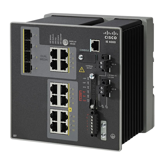
Page 7: Front Panel Overview
10 Dual-purpose ports (uplink ports) 1. Use a screwdriver to remove the port cover and access the port. Ports and Slots Different configurations are available. Not all ports or slots are present in all configurations. Note Cisco IE 4000 Switch Hardware Installation Guide... - Page 8 100BASE-TX traffic requires Category 5 cable. 10BASE-T traffic can use Category 3 or Category 4 cables. When connecting the switch to workstations, servers, routers, and Cisco IP phones, make sure that the cable is a straight-through cable. You can use the mdix auto interface configuration command in the command-line interface (CLI) to enable the automatic medium-dependent interface crossover (auto-MDIX) feature.
-
Page 9: Management Ports
The USB-mini console interface speeds are the same as the RJ-45 console interface speeds. To use the USB-mini console port, you must install the Cisco Windows USB device driver on the device that is connected to the USB-mini console port and that is running Microsoft Windows. -
Page 10: Power Connectors
DC source with the higher voltage. If one of the two power sources fail, the other continues to power the switch. Cisco IE 4000 Switch Hardware Installation Guide Cisco IE 4000 Switch Hardware Installation Guide... -
Page 11: Alarm Connector
1 Gb SFP (for DL & UL) Distance Mode GLC-SX-MM/ GLC-SX-MMD 220-550 m SFP-GE-S 220-550 m GLC-SX-MM-RGD 220-550 m GLC-LH-SM/ GLC-LH-SMD 550m/10km MMF/SMF SFP-GE-L 550m/10km MMF/SMF GLC-LX-SM-RGD 550m/10km MMF/SMF GLC-T 100 m CAT5 GLC-BX-U 10km Cisco IE 4000 Switch Hardware Installation Guide... - Page 12 SFP-GE-Z 70km GLC-ZX-SM-RGD 70km 100 Mb SFP (for FE DL) Distance Fiber GLC-FE-100FX GLC-FE-100FX-RGD GLC-FE-100LX 10km GLC-FE-100LX-RGD 10km GLC-FE-100BX-U 10km GLC-FE-100BX-D 10km GLC-FE-100EX 40km GLC-FE-100ZX 80km Cisco IE 4000 Switch Hardware Installation Guide Cisco IE 4000 Switch Hardware Installation Guide...
- Page 13 You can use the LEDs to monitor the switch status, activity, and performance. Figure 1-4 Figure 1- show the front panel LEDs. Figure 1-4 LEDs on the Cisco IE 4000 Switch 10 11 12 13 14 USB mini-Type B (console) port LED 6 Alarm LEDs Express Setup LED...
-
Page 14: System Led
Alarm LEDs Alarm OUT Color System Status Alarm OUT is not configured, or the switch is off. Green Alarm OUT is configured, no alarm detected. Cisco IE 4000 Switch Hardware Installation Guide 1-10 Cisco IE 4000 Switch Hardware Installation Guide... -
Page 15: Power Status Leds
The power status LEDs only show that power is present if the voltage at the switch input exceeds the valid level. For information about the power LED colors during the boot fast sequence, see the “Verifying Switch Operation” section on page 2-31. Cisco IE 4000 Switch Hardware Installation Guide 1-11... -
Page 16: Port Status Leds
Noncompliant cabling or powered devices can cause a PoE port fault. Caution Use only standard-compliant cabling to connect Cisco pre-standard IP Phones and wireless access points or IEEE 802.3af-compliant devices. You must remove any cable or device that causes a PoE fault. -
Page 17: Rear Panel
DIN rail and return to the original position to secure the switch to a DIN rail. Figure 1-5 Cisco IE 4000 Switch Rear Panel Management Options The switch supports these management options: Cisco IE 4000 Switch Hardware Installation Guide 1-13... -
Page 18: Network Configurations
Cisco Network Assistant is a PC-based network management GUI application optimized for LANs of small- and medium-sized businesses. Using the GUI, you can configure and manage switch clusters or standalone switches. Cisco Network Assistant is available at no cost and can be downloaded from this URL: http://www.cisco.com/en/US/products/ps5931/tsd_products_support_series_home.html... -
Page 19: Table Of Contents
Where to Go Next, page 2-31 • Preparing for Installation This section provides information about these topics: Warnings, page 2-2 • Installation Guidelines, page 2-4 • Installation Guidelines, page 2-4 • Verifying Package Contents, page 2-6 • Cisco IE 4000 Switch Hardware Installation Guide... - Page 20 Only trained and qualified personnel should be allowed to install, replace, or service this equipment. Statement 1030 Ultimate disposal of this product should be handled according to all national laws and Warning regulations. Statement 1040 Cisco IE 4000 Switch Hardware Installation Guide...
- Page 21 Explosion Hazard—Substitution of components may impair suitability for Class I, Division 2/Zone 2. Statement 1083 When installed in a Class I, Div/Zone 2 hazardous location environment, this equipment must be Caution installed in a min. IP54, ATEX certified enclosure. Cisco IE 4000 Switch Hardware Installation Guide...
-
Page 22: Installation Guidelines
– Sides: 2.0 in. (50.8 mm) – Front: 2.0 in. (50.8 mm) Contact your Cisco Technical Assistance Centre (TAC) if tighter spacings are required. When installed in a Class I, Div/Zone 2 hazardous location environment, this equipment must be Caution... -
Page 23: General Guidelines
Preparing for Installation General Guidelines Before installation, observe these general guidelines: Proper ESD protection is required whenever you handle Cisco equipment. Installation and Caution maintenance personnel should be properly grounded by using ground straps to eliminate the risk of ESD damage to the switch. -
Page 24: Installing Or Removing The Flash Memory Card (Optional)
Installing or Removing the Flash Memory Card (Optional) Verifying Package Contents If any item is missing or damaged, contact your Cisco representative or reseller for support. Installing or Removing the Flash Memory Card (Optional) The software/firmware is stored on the SD card memory from factory default. Optionally, you can execute the sync command to copy the software/firmware (including directory) to on-board memory (flash memory), then remove the SD card. -
Page 25: Connecting To A Console Port (Optional)
For DC power connections, use UL- and CSA-rated, style 1007 or 1569 twisted-pair copper • appliance wiring material (AWM) wire. Wire-stripping tools for stripping 10- and 18-gauge wires. • A number-2 Phillips screwdriver. • A flat-blade screwdriver. • Cisco IE 4000 Switch Hardware Installation Guide... - Page 26 The enclosure must meet IP 54 or NEMA type 4 minimum enclosure rating standards. Statement 1063 To prevent the switch assemble from overheating, there must be sufficient spacings as explained under Caution Appendix 2, “Installation Guidelines”, between any other switch assembly. Cisco IE 4000 Switch Hardware Installation Guide...
-
Page 27: Grounding The Switch
Insert the ground wire into the ring terminal lug, and using a crimping tool, crimp the terminal to the Step 3 wire. See Figure 2-2. If two ring terminals are being used, repeat this action for a second ring terminal. Cisco IE 4000 Switch Hardware Installation Guide... - Page 28 Ground-Lug Screw Attach the other end of the ground wire to a grounded bare metal surface, such as a ground bus, a Step 7 grounded DIN rail, or a grounded bare rack. Cisco IE 4000 Switch Hardware Installation Guide 2-10...
-
Page 29: Connecting The Power Converter To An Ac Power Source
Ensure that only wire with insulation extends from the connectors. Tighten the line and neutral terminal block screws. Step 5 Torque to 10 in-lb (1.13Nm). Note Cisco IE 4000 Switch Hardware Installation Guide 2-11... -
Page 30: Connecting The Power Converter To A Dc Power Source
2-3) lead into the line wire connection. Ensure that only wire with insulation extends from the connectors. See Figure 2-3. Tighten the line and neutral terminal block screws. Step 8 Torque to 8 in.-lb, not to exceed 10 in-lb. Note Cisco IE 4000 Switch Hardware Installation Guide 2-12... -
Page 31: Wiring The Dc Power Source
DC-A and DC-B Power Connector Labels Label Connection Positive DC power connection – Return DC power connection Measure two strands of twisted-pair copper wire (16-to-18 AWG) long enough to connect to the DC Step 3 power source. Cisco IE 4000 Switch Hardware Installation Guide 2-13... - Page 32 An exposed wire lead from a DC-input power source can conduct harmful levels of electricity. Be sure that no exposed portion of the DC-input power source wire extends from the connector(s) or terminal block(s). Statement 122 Cisco IE 4000 Switch Hardware Installation Guide 2-14...
- Page 33 Use a ratcheting torque flathead screwdriver to torque the power connector captive screws (above the Step 7 installed wire leads) to 5in-lb (0.565 Nm). See Figure 2-7. Do not over-torque the power connector’s captive screws. The torque should not exceed 5in-lb (0.565 Caution Nm). Cisco IE 4000 Switch Hardware Installation Guide 2-15...
- Page 34 Step 4 through Step 8 using the second power connector. Figure 2-8 shows the completed DC-input wiring on a power connector for a primary power source and an optional secondary power source. Cisco IE 4000 Switch Hardware Installation Guide 2-16...
- Page 35 Failure to securely tighten the captive screws can result in an electrical arc if the connector is Warning accidentally removed. Statement 397 This product relies on the building’s installation for short-circuit (overcurrent) protection. Warning Ensure that the protective device is rated not greater than: 7.5A. Statement 1005 Cisco IE 4000 Switch Hardware Installation Guide 2-17...
-
Page 36: Applying Power To The Power Converter
To apply power to a switch that is directly connected to a DC power source, locate the circuit breaker on the panel board that services the DC circuit, and switch the circuit breaker to the ON position. Cisco IE 4000 Switch Hardware Installation Guide 2-18... -
Page 37: Disconnecting Power
Boot fast failures are usually fatal. Call Cisco TAC immediately if your switch does not complete boot Note fast successfully. You can disable the boot fast and run POST by using the Cisco IOS CLI. See the Cisco IE 4000 Switch Note Software Configuration Guide for more information. -
Page 38: Installing The Switch On A Din Rail
Step 2 over the top of the DIN rail. See Figure 2-9. Do not stack any equipment on the switch. Caution Figure 2-9 Position the Hooks Over the DIN Rail DIN Rail Switch Cisco IE 4000 Switch Hardware Installation Guide 2-20... -
Page 39: Removing The Switch From A Din Rail
DIN rail. See Figure 2-10. Pull the bottom of the switch away from the DIN rail, and lift the hooks off the top of the DIN rail. See Step 3 Figure 2-10. Cisco IE 4000 Switch Hardware Installation Guide 2-21... - Page 40 Chapter 2 Switch Installation Installing the Switch Figure 2-10 Releasing the Spring-Loaded Latch from the DIN Rail Push latch down Remove the switch from the DIN rail. Step 4 Cisco IE 4000 Switch Hardware Installation Guide 2-22...
-
Page 41: Connecting Alarm Circuits
The input voltage source of the alarm output relay circuit must be an isolated source and limited to less Caution than or equal to 24 VDC, 1.0 A or 48 VDC, 0.5 A. Cisco IE 4000 Switch Hardware Installation Guide 2-23... - Page 42 Insert the exposed wires for the external alarm device into the connections based on an alarm input or Step 4 output circuit setup (see Table 2-3). For example, to wire an alarm input circuit, complete the IN1 and REF connections (See Figure 2-12). Cisco IE 4000 Switch Hardware Installation Guide 2-24...
- Page 43 2 in-lb (0.23 N-m). (See Figure 2-13.) Do not over-torque the power and alarm connectors’ captive screws. The torque should not exceed Caution 2 in-lb (0.23 N-m). Figure 2-13 Securing the Alarm Connector Captive Screws Cisco IE 4000 Switch Hardware Installation Guide 2-25...
- Page 44 Be sure that power cannot be accidentally turned on or verify that the area is nonhazardous before proceeding. Statement 1058 Cisco IE 4000 Switch Hardware Installation Guide 2-26...
-
Page 45: Connecting Destination Ports
Caution procedures. To connect to 10BASE-T, 100BASE-TX or 1000BASE-T devices, follow these steps: When connecting to workstations, servers, routers, and Cisco IP phones, connect a straight-through Step 1 cable to an RJ-45 connector on the front panel. When connecting to 1000BASE-T-compatible devices, use a twisted four-pair, Category 5 or higher cable. -
Page 46: Installing And Removing Sfp Modules
(TX) and receive (RX). You can use any combination of rugged SFP modules. See the release notes on Cisco.com for the list of supported modules. Each SFP module must be of the same type as the SFP module on the other end of the cable, and the cable must not exceed the stipulated cable length for reliable communications. -
Page 47: Removing Sfp Modules From Sfp Module Slots
If the module has a bale-clasp latch, pull the bale out and down to eject the module. If the bale-clasp latch is obstructed and you cannot use your index finger to open it, use a small, flat-blade screwdriver or other long, narrow instrument to open the bale-clasp latch. See Figure 2-15. Cisco IE 4000 Switch Hardware Installation Guide 2-29... -
Page 48: Connecting To Sfp Modules
See Chapter 4, “Troubleshooting,” for solutions to cabling problems. If necessary, reconfigure and restart the switch or the target device. Step 5 Cisco IE 4000 Switch Hardware Installation Guide 2-30... -
Page 49: Verifying Switch Operation
You can change this setting and configure the port to recognize only an RJ-45 connector or only an SFP module by using the media type interface configuration command. For more information, see the Cisco IE 4000 Switch Command Reference. Verifying Switch Operation Before installing the switch in its final location, power on the switch, and verify that the switch powers up in boot fast style. - Page 50 Chapter 2 Switch Installation Where to Go Next Start the Cisco Network Assistant application, which is described in the Getting Started with Cisco • Network Assistant guide. Using the GUI, you can configure and monitor a switch cluster or an individual switch.
-
Page 51: Accessing The Cli Through The Console Port
Warnings, page 2-2 For installation procedures, see Chapter 2, “Switch Installation.” Accessing the CLI Through the Console Port You can enter Cisco IOS commands and parameters through the CLI. Use one of these options to access the CLI: RJ-45 Console Port •... - Page 52 Start the terminal-emulation program on the PC or the terminal. The program, frequently a PC Step 2 application such as HyperTerminal or ProcommPlus, makes communication between the switch and your PC or terminal possible. Cisco IE 4000 Switch Hardware Installation Guide...
- Page 53 2-7. Step 4 The PC or terminal displays the bootloader sequence. Press Enter to display the setup prompt. Follow Step 5 the steps in the “Completing the Setup Program” section on page A-8. Cisco IE 4000 Switch Hardware Installation Guide...
-
Page 54: Installing The Cisco Microsoft Windows Usb Device Driver
Choose Start > Control Panel > Systems. Click the Hardware tab and choose Device Manager. Expand the Ports section. The assigned COM port appears in parenthesis at the end of the line with this entry: Cisco USB System Management Console. -
Page 55: Installing The Cisco Microsoft Windows Xp Usb Driver
Obtain the file Cisco_usbconsole_driver.zip from the Cisco.com web site and unzip it. Step 1 You can download the driver file from the Cisco.com site for downloading the switch software. Note If using 32-bit Windows XP, double-click the setup.exe file in the Windows_32 folder. If using 64-bit Step 2 Windows XP, double-click the setup(x64).exe file in the Windows_64 folder. - Page 56 Connect the USB cable to the PC and the switch console port. The USB console port LED turns green, Step 6 and the Found New Hardware Wizard appears. Follow the instructions to complete the driver installation. Cisco IE 4000 Switch Hardware Installation Guide...
-
Page 57: Uninstalling The Cisco Microsoft Windows Usb Driver
Uninstalling the Cisco Microsoft Windows USB Driver Uninstalling the Cisco Microsoft Windows XP and 2000 USB Driver • Uninstalling the Cisco Microsoft Windows Vista and Windows 7 USB Driver • Uninstalling the Cisco Microsoft Windows XP and 2000 USB Driver Use the Windows Add or Remove Programs utility or the setup.exe file. -
Page 58: Entering The Initial Configuration Information
You must assign an IP address and other configuration information necessary for the switch to communicate with the local routers and the Internet. This information is also required if you plan to use Device Manager or Cisco Network Assistant to configure and manage the switch. IP Settings... - Page 59 If you enter N, the switch appears as a candidate switch in the Cisco Network Assistant GUI. You can configure the switch as a command switch later through the CLI, Device Manager, or the Cisco Network Assistant application.
- Page 60 Telnet. For configuration information, see the switch Cisco IE 4000 Switch Software Configuration Guide. To use the Cisco Network Assistant, see the Getting Started with Cisco Network Assistant guide on Cisco.com. Cisco IE 4000 Switch Hardware Installation Guide...
-
Page 61: Troubleshooting
Boot fast failures are usually fatal. Contact your Cisco TAC representative if your switch does not Note successfully complete boot fast. You can disable the boot fast and run POST by using the Cisco IOS CLI, see the Cisco IE 4000 Switch Note Software Configuration Guide for more information. -
Page 62: Switch Leds
Verify that you are using the correct cable type. See Appendix C, “Cables and Adapters” • information. Look for loose connections. Sometimes a cable appears to be seated but is not. Disconnect the cable, • and then reconnect it. Cisco IE 4000 Switch Hardware Installation Guide... -
Page 63: Sfp Module
• SFP Module Use only Cisco SFP modules. Each Cisco module has an internal serial EEPROM that is encoded with security information. This encoding verifies that the module meets the requirements for the switch. Inspect the SFP module. Exchange the suspect module with a known good module. -
Page 64: Switch Performance
If the port statistics show excessive FCS, late-collision, or alignment errors, verify that the cable distance from the switch to the connected device meets the recommended guidelines. See the “Cables and Adapters” section on page C-4. Cisco IE 4000 Switch Hardware Installation Guide... -
Page 65: Resetting The Switch
For this procedure, see the “How to Recover Passwords” section on page 4-5. The Cisco IE 4000 Switch Software Configuration Guide provides details about enabling and disabling the password recovery feature and the procedure for recovering passwords. Cisco IE 4000 Switch Hardware Installation Guide... -
Page 66: Finding The Switch Serial Number
Finding the Switch Serial Number Finding the Switch Serial Number If you contact Cisco Technical Assistance, you need to know the serial number of your switch. The serial number is on the compliance label on the right-hand side of the switch. See Figure 4-1. -
Page 67: Technical Specifications
The safety certifications apply only to ambient temperatures under 158°F (70°C). However, the Note Cisco IE 4000 switch can function in the substation and traffic signal installations under the environmental conditions shown in Table B-1. - Page 68 Appendix B Technical Specifications Technical Specifications Technical Specifications Table B-2 lists the technical specifications for the Cisco IE 4000 switches. Table B-2 Cisco IE 4000 Series Technical Specifications Environmental Ranges Storage temperature –40 to 185°F (–40 to 85°C) Operating temperature -40C to 158F (-40 to 70C).
- Page 69 Appendix B Technical Specifications Technical Specifications Table B-2 Cisco IE 4000 Series Technical Specifications (continued) IE-4000-4GC4GP4G-E • IE-4000-4TC4G-E • IE-4000-4S8P4G-E • IE-4000-4GS8GP4G-E • IE-4000-16GT4G-E: • IE-4000-8S4G-E • IE-4000-8GS4G-E • Physical Dimensions Weight All IE4000 models listed in Table 1: 6.35 pounds (2.88 kg) PWR-IE170W-PC-AC=: 3.88 pounds (1.76 kg)
-
Page 70: Alarm Ratings
Appendix B Technical Specifications Alarm Ratings Alarm Ratings Table B-3 lists the alarm ratings for the Cisco IE 4000 switches. Table B-3 Alarm Input and Output Ratings Alarm Ratings Specification Alarm input electrical specification No power required—open or closed state detected. -
Page 71: Connector Specifications
4 5 6 7 8 For the three models of IE 4000 switch that support PoE, connector pins 4 and 5 supply +48 VDC and Note pins 7 and 8 are the DC voltage return lines. Cisco IE 4000 Switch Hardware Installation Guide... -
Page 72: Sfp Module Connectors
The switch has two console ports: a USB 5-pin mini-Type B port on the front panel (see Figure C-4) and an RJ-45 console port on the rear panel. Figure C-4 USB Mini-Type B Port Cisco IE 4000 Switch Hardware Installation Guide... -
Page 73: Alarm Port
Alarm Connector Labels (Top to Bottom) Label Connection Alarm Output Normally Open (NO) connection Alarm Output Common connection Alarm Output Normally Closed (NC) connection Alarm Input 2 Alarm Input Reference Ground connection Alarm Input 1 Cisco IE 4000 Switch Hardware Installation Guide... -
Page 74: Cables And Adapters
G.652 — 6.2 miles (10 km) BX10-U 1310 RX 1000BASE-LX/ GLC-LH-SM 1310 62.5/125 1804 feet (550 m) 50/125 1804 feet (550 m) 50/125 1804 feet (550 m) G.652 — 6.2 miles (10 km) Cisco IE 4000 Switch Hardware Installation Guide... - Page 75 62.5/125 722 feet (220 m) 62.5/125 902 feet (275 m) 50/125 1640 feet (500 m) 50/125 1804 feet (550 m) 1000BASE-ZX GLC-ZX-SM- 1550 G.652 — 43.4 to 62 miles (70 to 100 km) Cisco IE 4000 Switch Hardware Installation Guide...
- Page 76 1804 feet (550 m) 50.0 1804 feet (550 m) 50.0 1804 feet (550 m) G.652 — 6.2 miles (10 km) 100BASE-ZX SFP-GE-Z 1550 9/10 — 43.5 miles (70 km) 62 miles (100 km) Cisco IE 4000 Switch Hardware Installation Guide...
-
Page 77: Cable Pinouts
Router or PC 1 TP0+ 1 TP0+ 2 TP0- 2 TP0- 3 TP1+ 3 TP1+ 6 TP1- 6 TP1- 4 TP2+ 4 TP2+ 5 TP2- 5 TP2- 7 TP3+ 7 TP3+ 8 TP3- 8 TP3- Cisco IE 4000 Switch Hardware Installation Guide... -
Page 78: Console Port Adapter Pinouts
PC console port. You need to provide an RJ-45-to-DB-25 female DTE adapter if you want to connect the switch console port to a terminal. You can order an adapter (part number ACS- DSBUASYN=). For console port and adapter pinout information, see Table C-5 Table C-6. Cisco IE 4000 Switch Hardware Installation Guide... - Page 79 The RJ-45-to-DB-25 female DTE adapter is not supplied with the switch. You can order this adapter from Note Cisco (part number ACS-DSBUASYN=). Table C-6 Console Port Signaling Using a DB-25 Adapter Switch Console RJ-45-to-DB-25 Console Port (DTE) Adapter Device Signal DB-25 Pin Signal Cisco IE 4000 Switch Hardware Installation Guide...
- Page 80 Appendix C Cable and Connectors Cables and Adapters Cisco IE 4000 Switch Hardware Installation Guide C-10...
- Page 81 A P P E N D I X Hazardous Location Installation Information This appendix provides hazardous location installation information for the Cisco IE 4000 switches. Hazardous Area Installation Warnings Exposure to some chemicals could degrade the sealing properties of materials used in the sealed Warning relay device.
- Page 82 Be sure that power is removed or the area is nonhazardous before proceeding. Statement 1087 This equipment is only suitable for use in Class I, Division 2, Groups A, B, C, D, or nonhazardous Caution locations. Cisco IE 4000 Switch Hardware Installation Guide...
-
Page 83: North American Hazardous Location Approval
IEC 364-3. In addition, if equipment is operated in a domestic environment, interference could occur. Hazardous Locations Standards Table D-1 lists the hazardous location standards for the Cisco IE 4000 switches. Cisco IE 4000 Switch Hardware Installation Guide... - Page 84 IEC 60079-0 6th Edition IEC 60079-0, 6e édition IEC 60079-15 4th Edition IEC 60079-15, 4e édition UL 60079-0, 5th Ed, 2009-10-21 UL 60079-0, 5e éd., 21-10-2009 UL 60079-15, 3rd Ed, 2009-7-17 UL 60079-15, 3e éd., 17-07-2009 Cisco IE 4000 Switch Hardware Installation Guide...