Siemens RUGGEDCOM RX1400 Installation Manual
Hide thumbs
Also See for RUGGEDCOM RX1400:
- Installation manual (62 pages) ,
- Reference manual (148 pages) ,
- Installation manual (66 pages)

Related Manuals for Siemens RUGGEDCOM RX1400


Summary of Contents for Siemens RUGGEDCOM RX1400
- Page 1 Preface Introduction Installing the Device RUGGEDCOM RX1400 Communication Ports Technical Specifications Dimension Drawings Installation Guide Certification 3/2015 RC1103-EN-04...
- Page 2 Warranty Siemens warrants this product for a period of five (5) years from the date of purchase, conditional upon the return to factory for maintenance during the warranty term. This product contains no user-serviceable parts. Attempted service by unauthorized personnel shall render all warranties null and void.
-
Page 3: Table Of Contents
RUGGEDCOM RX1400 Installation Guide Table of Contents Table of Contents Preface ........................ Alerts ..............................v Related Documents ..........................v Accessing Documentation ........................v Training .............................. vi Customer Support ..........................vi Chapter 1 Introduction ......................1.1 Feature Highlights ........................1 1.2 Description ..........................2 Chapter 2 Installing the Device .................... - Page 4 RUGGEDCOM RX1400 Table of Contents Installation Guide Chapter 4 Technical Specifications ..................4.1 Power Supply Specifications ....................... 21 4.2 Failsafe Alarm Relay Specifications ..................... 21 4.3 Fast Ethernet Port Specifications ....................22 4.4 Serial Port Specifications ......................22 4.5 SFP Optic Ethernet Port Specifications ..................22 4.6 Cellular Modem Specifications ....................
-
Page 5: Preface
Installation Guide Preface Preface This guide describes the RUGGEDCOM RX1400. It describes the major features of the device, installation, commissioning and important technical specifications. It is intended for use by network technical support personnel who are responsible for the installation, commissioning and maintenance of the device. -
Page 6: Training
Siemens sales representative. Customer Support Customer support is available 24 hours, 7 days a week for all Siemens customers. For technical support or general information, contact Siemens Customer Support through any of the following methods: • Online Visit http://www.siemens.com/automation/support-request... -
Page 7: Introduction
Introduction Introduction The RUGGEDCOM RX1400 is a multi-protocol intelligent node that combines Ethernet switch, routing and firewall functionality with various wide area connectivity options. The RX1400 switch, with its rugged metal housing, is designed for DIN rail, panel or rack mounting. -
Page 8: Description
Chapter 1 RUGGEDCOM RX1400 Introduction Installation Guide Power Supply • SMA connectors for RF interfaces • 12 or 24 Cyber Security • Passwords – compliant with NERC guidelines including provision for RADIUS-based authentication • SSH/SSL – extends capability of password protection to add encryption of passwords and data as they cross the network •... - Page 9 RUGGEDCOM RX1400 Chapter 1 Installation Guide Introduction ▪ ALARM LED – Illuminates when an alarm condition exists. ▪ CELL LED – Indicates when the cellular modem is connected to the network. ○ Solid = Activity ○ Off = No activity ▪...
- Page 10 RUGGEDCOM RX1400 Chapter 1 Installation Guide Introduction Description...
-
Page 11: Installing The Device
This product contains no user-serviceable parts. Attempted service by unauthorized personnel shall render all warranties null and void. Changes or modifications not expressly approved by Siemens Canada Ltd. could invalidate specifications, test results, and agency approvals, and void the user's authority to operate the equipment. -
Page 12: Required Tools And Materials
û Braided or equivalent ground wire for grounding the device û For more information, contact a Siemens Sales representative. Section 2.2 Mounting the Device The RX1400 is designed for maximum mounting and display flexibility. It can be equipped with brackets that allow it to be installed in a 48 cm (19 in) rack, 35 mm (1.4 in) DIN rail, or directly on a panel. -
Page 13: Mounting The Device On A Din Rail
RUGGEDCOM RX1400 Chapter 2 Installation Guide Installing the Device • When installing the device in a closed or multi-device rack, be aware the operating ambient temperature of the rack may be higher than the ambient temperature of the room. Make sure the rack is installed in a suitable environment that can withstand the maximum ambient temperature generated by the rack. -
Page 14: Mounting The Device To A Panel
Chapter 2 RUGGEDCOM RX1400 Installing the Device Installation Guide Figure 3: DIN Rail Mounting 1. Panel/DIN Rail Adapter 2. DIN Rail 3. Screw Install one of the supplied screws on either side of the device to secure the adapters to the DIN rails. -
Page 15: Installing The Antennas
RUGGEDCOM RX1400 Chapter 2 Installation Guide Installing the Device IMPORTANT! Before installing the device, note the following: • An appropriately rated DC circuit breaker must be installed. • Use only #16 gage copper wiring when connecting terminal blocks. • Equipment must be installed according to applicable local wiring codes and standards. - Page 16 IMPORTANT! A Radio Frequency (RF) site survey is recommended prior to any installation to help determine the best location for the LTE and GPS antennas. For assistance, contact a Siemens Sales representative. IMPORTANT! The cellular modem supports SISO (Single Input Single Output) and MIMO (Multiple Input Multiple Output) modes.
-
Page 17: Installing The Sim Cards
RUGGEDCOM RX1400 Chapter 2 Installation Guide Installing the Device • 9.0 dBi at 700 MHz • 6.0 dBi at 1700 MHz Under no conditions may an antenna gain be used that would exceed the ERP and/or EIRP power limits specified in FCC 47 CFR Parts 22, 24, 27 and 90. -
Page 18: Connecting The Failsafe Alarm Relay
Chapter 2 RUGGEDCOM RX1400 Installing the Device Installation Guide Remove the SIM card access panel. Figure 7: Accessing the SIM Cards 1. Access Panel 2. Secondary Micro-SIM Card 3. Primary Micro-SIM Card Insert the SIM cards into the slots. Slot 1 is for the primary SIM card and slot 2 is for the secondary (backup) SIM card. -
Page 19: Connecting To The Device
Chapter 3, Communication Ports. Section 2.8 Cabling Recommendations Siemens recommends using SIMATIC NET industrial Ethernet shielded cables for all Ethernet ports. Refer to the following sections for further recommendations and considerations: • Section 2.8.1, “Protection On Twisted-Pair Data Ports” •... -
Page 20: Protection On Twisted-Pair Data Ports
Section 2.8.1 Protection On Twisted-Pair Data Ports Siemens does not recommend the use of copper cabling of any length for critical, real-time substation automation applications. All copper Ethernet ports on RUGGEDCOM products include transient suppression circuitry to protect against damage from electrical transients and conform with IEC 61850-3 and IEEE 1613 Class 1 standards. -
Page 21: Communication Ports
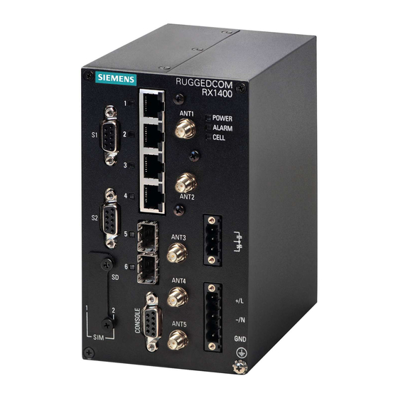
RUGGEDCOM RX1400 Chapter 3 Installation Guide Communication Ports Communication Ports The RX1400 can be equipped with various types of communication ports to enhance its abilities and performance. Figure 10: Port Assignment 1. Serial DB9 Ports 2. SIM Card Slots 3. LTE MAIN Port 4. -
Page 22: Fast Ethernet Ports
Chapter 3 RUGGEDCOM RX1400 Communication Ports Installation Guide Section 3.1 Fast Ethernet Ports The RX1400 features four 10/100Base-TX fast Ethernet (FE) ports with RJ45 connectors. The RJ45 connectors are directly connected to the chassis ground on the device and can accept CAT-5 shielded twisted-pair (STP) cables. -
Page 23: Installing An Sfp Optical Port
To install an SFP optical port, do the following: CAUTION! Electrical hazard – risk of damage to equipment. Use only components certified by Siemens with RUGGEDCOM products. Damage to the module and device may occur if compatibility and reliability have not been properly assessed. -
Page 24: Removing An Sfp Optical Port
Chapter 3 RUGGEDCOM RX1400 Communication Ports Installation Guide Insert the port into the module and swing the bail-latch up to lock it in place. Figure 13: Installing an SFP Optical Port (Typical) 1. SFP Optical Port 2. Metal Bail-Latch Remove the dust cover from the port. -
Page 25: Serial Ports
RUGGEDCOM RX1400 Chapter 3 Installation Guide Communication Ports Section 3.3 Serial Ports The RX1400 supports two serial ports with DB9 connectors, which can be run in RS232, RS485 or RS422 mode. For technical specifications, refer to Section 4.4, “Serial Port Specifications”. - Page 26 Chapter 3 RUGGEDCOM RX1400 Communication Ports Installation Guide 120Ω 10nF 120Ω 10nF Figure 16: Recommended RS485 Wiring 1. RX1400 Device 2. Common (Isolated Ground) 3. Negative 4. Positive 5. Shield to Earth (Connected At a Single Point) 6. RS485 Devices (32 Total)
-
Page 27: Technical Specifications
RUGGEDCOM RX1400 Chapter 4 Installation Guide Technical Specifications Technical Specifications The following sections provide important technical specifications related to the device: • Section 4.1, “Power Supply Specifications” • Section 4.2, “Failsafe Alarm Relay Specifications” • Section 4.3, “Fast Ethernet Port Specifications”... -
Page 28: Fast Ethernet Port Specifications
NOTE • Maximum segment length is greatly dependent on factors such as fiber quality, and the number of patches and splices. Consult a Siemens sales associate when determining maximum segment distances. • All optical power numbers are listed as dBm averages. -
Page 29: Cellular Modem Specifications
RUGGEDCOM RX1400 Chapter 4 Installation Guide Technical Specifications Speed Connector Distance Interface Mode Tx λ (nm) Tx min (dBm) Tx max (dBm) (Mbit/s) Type (km) 1000 1550 — — 1000 — 1310 1490 1000 — 1310 1490 1000 — 1490... - Page 30 Chapter 4 RUGGEDCOM RX1400 Technical Specifications Installation Guide Band Network 1.4 MHz 3 MHz 5 MHz 10 MHz 15 MHz 20 MHz Band 5 AT&T ü ü ü ü û û Band 7 Europe û û ü ü ü ü...
-
Page 31: Operating Environment
RUGGEDCOM RX1400 Chapter 4 Installation Guide Technical Specifications • Velocity: < 0.2 m/s or 0.7 ft/s Sensitivity • Tracking: -161 dBm • Acquisition (Assisted, Non-LTE): -158 dBm • Acquisition (Assisted, LTE): -153 dBm • Acquisition (Standalone): -145 dBm Operational Limits Altitude <... -
Page 32: Mechanical Specifications
Chapter 4 RUGGEDCOM RX1400 Technical Specifications Installation Guide Section 4.8 Mechanical Specifications Parameter Value Dimensions Refer to Chapter 5, Dimension Drawings Weight 2.5 kg (5.5 lb) Ingress Protection IP40 Enclosure Aluminum Mechanical Specifications... -
Page 33: Dimension Drawings
RUGGEDCOM RX1400 Chapter 5 Installation Guide Dimension Drawings Dimension Drawings NOTE All dimensions are in millimeters, unless otherwise stated. 130.1 Figure 17: Overall Dimensions... - Page 34 Chapter 5 RUGGEDCOM RX1400 Dimension Drawings Installation Guide 465.2 3 x 45° Figure 18: Rack Mount Dimensions...
- Page 35 RUGGEDCOM RX1400 Chapter 5 Installation Guide Dimension Drawings 142.1 Figure 19: Panel Mount Dimensions...
- Page 36 Chapter 5 RUGGEDCOM RX1400 Dimension Drawings Installation Guide 129.6 139.7 Figure 20: Din Rail Mount Dimensions...
-
Page 37: Certification
RUGGEDCOM RX1400 Chapter 6 Installation Guide Certification Certification The RX1400 device has been thoroughly tested to guarantee its conformance with recognized standards and has received approval from recognized regulatory agencies. • Section 6.1, “Agency Approvals” • Section 6.2, “FCC Compliance”... -
Page 38: Industry Canada Compliance
Chapter 6 RUGGEDCOM RX1400 Certification Installation Guide Section 6.3 Industry Canada Compliance CAN ICES-3 (A) / NMB-3 (A) Section 6.4 EMC and Environmental Type Tests The RX1400 has passed the following Electromagnetic Compatibility (EMC) and environmental tests. IEC 61850-3 EMC Type Tests... - Page 39 Severity Test Description Test Levels Levels DC Power Ports 5 kV Siemens-specified severity levels IEEE 1613 EMC Type Tests NOTE The RX1400 meets Class 1 requirements for copper ports. Test Description Test Levels IEEE 1613 HV Impulse Signal ports 5 kV (Fail-Safe Relay Output)