Siemens RUGGEDCOM RX1400 Installation Manual
Hide thumbs
Also See for RUGGEDCOM RX1400:
- Installation manual (39 pages) ,
- Reference manual (148 pages) ,
- Installation manual (66 pages)

Related Manuals for Siemens RUGGEDCOM RX1400


Summary of Contents for Siemens RUGGEDCOM RX1400
- Page 1 Preface Introduction Installing the Device RUGGEDCOM RX1400 Communication Ports Technical Specifications Dimension Drawings Installation Guide Certification 08/2017 RC1103-EN-08...
-
Page 2: Security Information
Warranty Siemens warrants this product for a period of five (5) years from the date of purchase, conditional upon the return to factory for maintenance during the warranty term. This product contains no user-serviceable parts. Attempted service by unauthorized personnel shall render all warranties null and void. - Page 3 RUGGEDCOM RX1400 Installation Guide Industry Sector Tel: +1 905 856 5288 300 Applewood Crescent Fax: +1 905 856 1995 www.siemens.com/ruggedcom Concord, Ontario Canada, L4K 5C7...
- Page 4 RUGGEDCOM RX1400 Installation Guide...
-
Page 5: Table Of Contents
RUGGEDCOM RX1400 Installation Guide Table of Contents Table of Contents Preface ......................Alerts ..............................ix Related Documents ..........................x Accessing Documentation ........................x Training ............................... x Customer Support ..........................x Chapter 1 Introduction ..................... 1.1 Feature Highlights ........................1 1.2 Description ........................... 2 Chapter 2 Installing the Device .................. - Page 6 RUGGEDCOM RX1400 Table of Contents Installation Guide 2.11 Connecting to the Device ......................23 2.12 Configuring the Device ......................24 Chapter 3 Communication Ports ..................3.1 Fast Ethernet Ports ........................25 3.2 SFP Transceivers ......................... 26 3.3 Serial Ports ..........................27 Chapter 4 Technical Specifications ..................
- Page 7 RUGGEDCOM RX1400 Installation Guide Table of Contents 6.1.15 Other Approvals ......................49 6.2 EMC and Environmental Type Tests ....................49...
- Page 8 RUGGEDCOM RX1400 Table of Contents Installation Guide viii...
-
Page 9: Preface
Installation Guide Preface Preface This guide describes the RUGGEDCOM RX1400. It describes the major features of the device, installation, commissioning and important technical specifications. It is intended for use by network technical support personnel who are responsible for the installation, commissioning and maintenance of the device. -
Page 10: Related Documents
Mobile App Install the Industry Online Support app by Siemens AG on any Android, Apple iOS or Windows mobile device and be able to: • Access Siemens' extensive library of support documentation, including FAQs and manuals • Submit SRs or check on the status of an existing SR •... -
Page 11: Introduction
The RUGGEDCOM RX1400 is a multi-protocol intelligent node that combines Ethernet switch, routing and firewall functionality with various wide area connectivity options. The RUGGEDCOM RX1400 switch, with its rugged metal housing, is designed for DIN rail, panel or rack mounting. The RUGGEDCOM RX1400 provides a high level of immunity to electromagnetic interference, heavy electrical surges, extreme temperature and humidity for reliable operation in harsh environments. -
Page 12: Description
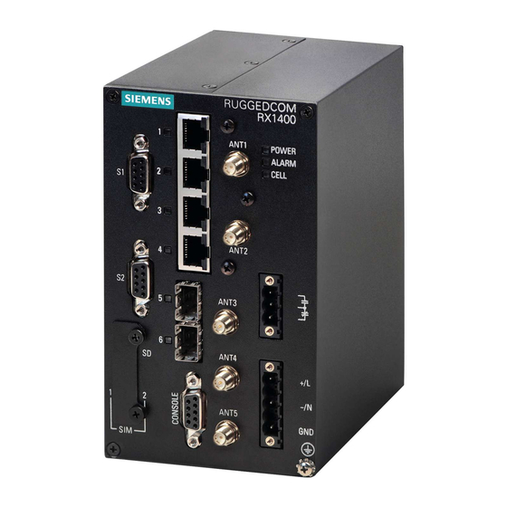
• R-SMA connectors for WLAN RF interface Section 1.2 Description The RUGGEDCOM RX1400 features various ports, controls and indicator LEDs on the front panel for connecting, configuring and troubleshooting the device. Figure 1: RUGGEDCOM RX1400 1. Serial Ports 2. Access Plate 3. Port Status LEDs 4. ANT1 Port 5. Fast Ethernet Ports 6. ANT2 Port 7. SFP Transceiver Ports ... - Page 13 RUGGEDCOM RX1400 Chapter 1 Installation Guide Introduction CELL LED Indicates when the cellular modem is connected to the network. • Solid = Activity • Off = No activity Port Status LEDs Indicate the status of each port: • Solid = Link •...
- Page 14 Chapter 1 RUGGEDCOM RX1400 Introduction Installation Guide Description...
-
Page 15: Installing The Device
This product contains no user-serviceable parts. Attempted service by unauthorized personnel shall render all warranties null and void. Changes or modifications not expressly approved by Siemens Canada Ltd could invalidate specifications, test results, and agency approvals, and void the user's authority to operate the equipment. -
Page 16: General Procedure
Connect power to the device and ground the device to safety Earth. Connect the device to the network. Configure the device. Section 2.2 Required Tools and Materials The following tools and materials are required to install the RUGGEDCOM RX1400: Tool/Material Available For Purchase From Siemens WLAN, LTE and/or GPS antennas ü... -
Page 17: Cabling Recommendations
Siemens also does not recommend using copper Ethernet ports to interface with devices in the field across distances that could produce high levels of ground potential rise (i.e. greater than 2500 V), during line-to-ground fault conditions. -
Page 18: Installing The Device In Hazardous Locations
Installing the Device in Hazardous Locations The RUGGEDCOM RX1400 is designed to comply with the safety standards for Class I, Division 2, Zone 2 hazardous locations where concentrations of flammable gases, vapors or liquids may be present, as opposed to normal operating environments. -
Page 19: Mounting The Device
Mounting the Device The RUGGEDCOM RX1400 is designed for maximum mounting and display flexibility. It can be equipped with brackets that allow it to be installed in a 48 cm (19 in) rack, 35 mm (1.4 in) DIN rail, or directly on a panel. -
Page 20: Mounting The Device On A Din Rail
To secure the device to a standard 48 cm (19 in) rack, do the following: Make sure the rack mount adapters are installed. Figure 3: Rack Mount Adapters 1. Rack Mount Adapter 2. RUGGEDCOM RX1400 Insert the assembly into the rack. Secure the adapters to the rack using the supplied hardware. -
Page 21: Mounting The Device To A Panel
Section 2.5.3 Mounting the Device to a Panel For panel installations, the RUGGEDCOM RX1400 can be equipped with panel adapters pre-installed on each side of the chassis. The adapters allow the device to be attached to a panel using screws. To mount the device to a panel, do the following: Place the device against the panel and align the adapters with the mounting holes. -
Page 22: Connecting The Antennas
Section 2.6 Connecting the Antennas The RUGGEDCOM RX1400 can be connected to external antennas for access to wireless networks. For increased signal coverage and improved performance, antennas are intended to be installed in a remote location separate from the RUGGEDCOM RX1400. -
Page 23: Available Antennas
RUGGEDCOM RX1400 Chapter 2 Installation Guide Installing the Device Section 2.6.1 Available Antennas The RUGGEDCOM RX1400 supports the following antennas. Cellular, GPS and WLAN Antennas Operating Antenna Type Frequency Gain (dBi) Article Number Reference (GHz) ANT1995-4MM Omni- 6GK6000-8NS01-1AA0 https://support.industry.siemens.com/cs/ Directional ww/en/view/109748485 0.7 to 1.0... - Page 24 Chapter 2 RUGGEDCOM RX1400 Installing the Device Installation Guide Operating Antenna Type Frequency Gain (dBi) Article Number Reference (GHz) ANT793-4MN Omni- 6GK5792-4MN00-0AA6 — Directional ANT793-6DG Directional 6GK5793-6DG00-0AA0 https://support.industry.siemens.com/cs/ ww/en/view/60509676 ANT793-6DT Omni- 6GK5793-6DT00-0AA0 https://support.industry.siemens.com/cs/ Directional ww/en/view/60510334 ANT793-6MN Omni- 6GK5793-6MN00-0AA6 https://support.industry.siemens.com/cs/ Directional...
-
Page 25: Connecting Lte Antennas
IMPORTANT! A Radio Frequency (RF) site survey is recommended prior to any installation to help determine the best location for the LTE antennas. For assistance, contact a Siemens Sales representative. IMPORTANT! The cellular modem supports SISO (Single Input Single Output) and MIMO (Multiple Input Multiple Output) modes. -
Page 26: Connecting A Gps Antenna
(SMPS). If needed, install a lightning protect between the antenna and the device. Figure 6: Antenna and Lightning Protector Assembly (Optional) 1. Drain Wire 2. RUGGEDCOM RX1400 3. Shielded Coaxial Cable 4. Lightning Protector 5. Ground Wire 6. LTE Antenna Section 2.6.3 Connecting a GPS Antenna For increased signal coverage and improved performance, the GPS antenna is intended to be installed in a remote location separate from the RX1400. - Page 27 IMPORTANT! A site survey is recommended prior to any installation to help determine the best location for the GPS antenna. For assistance, contact a Siemens Sales representative. IMPORTANT! Although it is impossible to protect the antenna from a direct lightning strike, the antenna and connected components can be protected from secondary effects through site selection and by installing protection devices.
-
Page 28: Connecting Wlan Antennas
Installation Guide Figure 7: Antenna and Lightning Protector Assembly (Optional) 1. Drain Wire 2. RUGGEDCOM RX1400 3. Shielded Coaxial Cable 4. Lightning Protector, Line Amplifier or Bandpass Filter 5. Ground Wire 6. GPS Antenna Using shielded coaxial cables, connect the antenna assembly to the ANT2 port on the device. -
Page 29: Installing The Sim Cards
Section 2.7 Installing the SIM Cards The RUGGEDCOM RX1400 supports dual micro-SIM cards for the LTE modem to provide a fail-over mechanism should one of the SIM cards lose connectivity with the network. To install micro-SIM cards from a regional cellular carrier, do the following: CAUTION! Static electricity hazard –... -
Page 30: Inserting/Removing The Microsd Card
RUGGEDCOM ROX II User Guide for the RUGGEDCOM RX1400. Section 2.8 Inserting/Removing the MicroSD Card The RUGGEDCOM RX1400 accepts a microSD card for storing configuration files and/or software updates. CAUTION! Configuration hazard – risk of data loss. The microSD card must not be removed or replaced during normal operation of the device. -
Page 31: Connecting The Failsafe Alarm Relay
1. Normally Closed 2. Common 3. Normally Open Section 2.10 Connecting Power The RUGGEDCOM RX1400 supports a single integrated high AC/DC or low DC power supply. IMPORTANT! Before installing the device, note the following: • An appropriately rated AC or DC circuit breaker must be installed. -
Page 32: Connecting High Ac/Dc Power
Chapter 2 RUGGEDCOM RX1400 Installing the Device Installation Guide Section 2.10.1 Connecting High AC/DC Power To connect a high AC/DC power supply to the device, do the following: CAUTION! Electrical hazard – risk of damage to equipment. Do not connect AC power cables to terminals for DC power. -
Page 33: Connecting To The Device
RUGGEDCOM RX1400 Chapter 2 Installation Guide Installing the Device Connect the power supply terminal block to the device. Figure 13: Terminal Block Wiring 1. Surge Ground Terminal 2. Negative Terminal 3. Positive Terminal 4. Braided Ground Cable 5. Power Supply Terminal Block Connect the positive wire from the power source to the positive terminal on the terminal block. -
Page 34: Configuring The Device
Reserved (Do Not Connect) For information about how to connect to the device via the serial console port, refer to the RUGGEDCOM ROX II CLI User Guide for the RUGGEDCOM RX1400. Communication Ports Connect any of the available Ethernet ports on the device to a management switch and access the RUGGEDCOM ROX II console and Web interfaces via the device's IP address. -
Page 35: Communication Ports
Installation Guide Communication Ports Communication Ports The RUGGEDCOM RX1400 can be equipped with various types of communication ports to enhance its abilities and performance. Figure 15: Port Assignment 1. Serial Ports 2. Access Plate 3. ANT1 Port 4. Fast Ethernet Ports 5. ANT2 Port 6. SFP Transceiver Ports 7. ANT3 Port 8. ANT4 Port ... -
Page 36: Sfp Transceivers
Link established Green (Blinking) Activity No link detected Compatible SFP Transceivers The following SFP transceivers are compatible with the RUGGEDCOM RX1400. For more information, including installation/removal instructions and ordering information, refer to the RUGGEDCOM SFP Transceiver Catalog [https://support.industry.siemens.com/cs/ca/en/view/109482309]. SFP Transceivers... -
Page 37: Serial Ports
1000 MM = Multi-Mode, SM = Single-Mode Section 3.3 Serial Ports The RUGGEDCOM RX1400 supports two serial ports with female DB9 connectors, which can be run in RS-232, RS-485 or RS-422 mode. For technical specifications, refer to Section 4.4, “Serial Port Specifications”. - Page 38 • The twisted pair should be terminated at each end of the chain. The following shows the recommended RS485 wiring. 120Ω 10nF 120Ω 10nF Figure 18: Recommended RS-485 Wiring 1. RUGGEDCOM RX1400 Device 2. Common (Isolated Ground) 3. Negative 4. Positive 5. Shield to Earth (Connected At a Single Point) 6. RS-485 Devices (32 Total) Serial Ports...
-
Page 39: Technical Specifications
Section 4.6, “WLAN Specifications” • Section 4.7, “Operating Environment” • Section 4.8, “Mechanical Specifications” Section 4.1 Power Supply Specifications The RUGGEDCOM RX1400 includes one of the following internal power supplies: Maximum Power Power Supply Type Input Range Internal Fuse Rating Consumption 88-264 VAC 98-300 VDC 3.15 A(T) -
Page 40: Fast Ethernet Port Specifications
Shielded or unshielded. Auto-crossover and auto-polarity. RMS 1 minute. Section 4.4 Serial Port Specifications The RUGGEDCOM RX1400 supports two serial ports with female DB9 connectors. For more information about the serial ports, refer to Section 3.3, “Serial Ports”. Baud Rate 1200 to 230400 kbps... -
Page 41: Cellular Modem Specifications
RUGGEDCOM RX1400 Chapter 4 Installation Guide Technical Specifications Section 4.5 Cellular Modem Specifications The following specifications detail the LTE, GNSS and WLAN capabilities of the cellular modem. CONTENTS • Section 4.5.1, “LTE Specifications” • Section 4.5.2, “GNSS Specifications” Section 4.5.1 LTE Specifications Supported LTE Frequency Bands... -
Page 42: Gnss Specifications
Chapter 4 RUGGEDCOM RX1400 Technical Specifications Installation Guide Band Network 1.4 MHz 3 MHz 5 MHz 10 MHz 15 MHz 20 MHz Band 13 AT&T û û ü ü û û Band 17 AT&T û û ü ü û û... -
Page 43: Wlan Specifications
RUGGEDCOM RX1400 Chapter 4 Installation Guide Technical Specifications Acquisition Time • Hot start: 1 s • Warm start: 29 s • Cold start: 32 s Accuracy • Horizontal: < 2 m 6.6 ft (50 %), < 5 m or 16.4 ft (90 %) •... -
Page 44: Operating Environment
Host Interface 4-Bit SDIO Maximum EIRP < 200 mW at 5250 to 5350 MHz Section 4.7 Operating Environment The RUGGEDCOM RX1400 can operate under the following environmental conditions: Parameter Range Comments Ambient Operating Temperature -40 to 85 °C Measured from a 30 cm (12 in) radius surrounding the center of the (-40 to 185 °F) -
Page 45: Dimension Drawings
RUGGEDCOM RX1400 Chapter 5 Installation Guide Dimension Drawings Dimension Drawings NOTE All dimensions are in millimeters, unless otherwise stated. 88.0 120.0 130.1 Figure 19: Overall Dimensions... - Page 46 Chapter 5 RUGGEDCOM RX1400 Dimension Drawings Installation Guide 465.2 3 x 45° 482.0 418.0 Figure 20: Rack Mount Dimensions...
- Page 47 RUGGEDCOM RX1400 Chapter 5 Installation Guide Dimension Drawings 142.1 Figure 21: Panel Mount Dimensions...
- Page 48 Chapter 5 RUGGEDCOM RX1400 Dimension Drawings Installation Guide 129.6 139.7 Figure 22: Din Rail Mount Dimensions...
-
Page 49: Certification
RUGGEDCOM RX1400 Chapter 6 Installation Guide Certification Certification The RUGGEDCOM RX1400 device has been thoroughly tested to guarantee its conformance with recognized standards and has received approval from recognized regulatory agencies. CONTENTS • Section 6.1, “Approvals” • Section 6.2, “EMC and Environmental Type Tests”... -
Page 50: Csa
• Class I, Division 2, Groups A, B, C, D • Ex nA nC IIC T4 Gc • Class I, Zone 2, AEx nA nC IIC T4 Gc A copy of the CSA Certificate of Compliance is available via Siemens Industry Online Support at https:// support.industry.siemens.com/cs/ww/en/view/109744578. -
Page 51: Tüv Süd
Section 6.1.4 European Union (EU) This device is declared by Siemens Canada Ltd to comply with essential requirements and other relevant provisions of the following EU directives: • Directive 1999/5/EC Directive 1999/5/EC of the European Parliament and of the Council of 9 March 1999 on Radio Equipment and Telecommunications Terminal Equipment and the Mutual Recognition of their Conformity •... - Page 52 The device is marked with a CE marking and notified body number, and can be used throughout the European community. 0682 A copy of the EU Declaration of Conformity is available via Siemens Industry Online Support at https:// support.industry.siemens.com/cs/ww/en/view/109475609. Notices specific to the European Union: IMPORTANT! For mobile and fixed operating configurations, in accordance with R&TTE Directive 1999/5/EC, the...
-
Page 53: Fcc
• Increase the separation between the device and receiver. • Connect the device into an outlet on a circuit different from that to which the receiver is connected • Contact Siemens Customer Support for assistance Notes specific to the FCC:... -
Page 54: Ised
RUGGEDCOM RX1400 Certification Installation Guide Section 6.1.8 ISED This device is declared by Siemens Canada Ltd to meet the requirements of the following ISED (Innovation Science and Economic Development Canada) standard: • CAN ICES-3 (B)/NMB-3 (B) Notices specific to ISED: NOTE This device is unable to transmit on the 5600 to 5650 MHz frequency band. - Page 55 RUGGEDCOM RX1400 Chapter 6 Installation Guide Certification IMPORTANT ! Cet appareil est conforme avec Santé Canada Code de sécurité 6. Le programme d ’installation de cet appareil doit s’ assurer que les rayonnements RF n’est pas émis au-delà de I’exigence de Santé Canada.
- Page 56 Chapter 6 RUGGEDCOM RX1400 Certification Installation Guide This device contains IC ID: 2417C-MC7355 WWAN Cellular/PCS GSM/EDGE/CDMA/WCDMA/LTE Modem. The WWAN antenna gain, including cable loss, must not exceed 3 dBi at 850 MHz, 3 dBi at 1900 MHz, 6 dBi at 700 MHz and 6 dBi at 1700 MHz.
-
Page 57: Ift
Radio Waves Act. As such, the device is marked with a KC symbol and can be used in the Republic of Korea (South Korea) as a Class B product in a commercial, industrial or business environment. MSIP-CMM-S14-RX1400 A copy of the KC Declaration of Conformity is available from Siemens Canada Ltd. For contact information, refer to “Contacting Siemens”. -
Page 58: Icasa
407 of the Telecommunication Act 1997 The device is marked with an RCM symbol to indicate compliance when sold in the Australian region. A copy of the Declaration of Conformity is available via Siemens Industry Online Support at https:// support.industry.siemens.com/cs/ww/en/view/109747499. -
Page 59: Rohs
Certification Section 6.1.14 RoHS This device is declared by Siemens Canada Ltd to meet the requirements of the following RoHS (Restriction of Hazardous Substances) directives for the restricted use of certain hazardous substances in electrical and electronic equipment: • China RoHS 2... - Page 60 Signal Ports 5 kV DC Power Ports Siemens-specified severity levels EMC Immunity Type Tests per IEEE 1613 NOTE The RUGGEDCOM RX1400 meets Class 1 requirements for copper ports, which allows for temporary communication loss. Test Description Test Levels IEEE 1613...
-
Page 61: Environmental Type Tests
RUGGEDCOM RX1400 Chapter 6 Installation Guide Certification Test Description Test Levels DC Power Ports Dielectric Strength Signal Ports 2828 VDC or 2 kV DC Power Ports Fast Transient (SWC) Signal Ports ± 4 kV @ 2.5 kHz, 5 kHz DC Power Ports... - Page 62 Chapter 6 RUGGEDCOM RX1400 Certification Installation Guide EMC and Environmental Type Tests...