Table of Contents
Advertisement
Advertisement
Table of Contents

Related Manuals for HP storevirtual 3200


Summary of Contents for HP storevirtual 3200
- Page 1 HPE StoreVirtual 3200 Storage User Guide Abstract This guide provides instructions for configuring individual storage systems, adding new disk drives or storage systems to existing configurations, and using remote support. Part Number: 839939-003 Published: March 2017 Edition: 3...
- Page 2 © 2016, 2017 Hewlett Packard Enterprise Development LP Notices The information contained herein is subject to change without notice. The only warranties for Hewlett Packard Enterprise products and services are set forth in the express warranty statements accompanying such products and services. Nothing herein should be construed as constituting an additional warranty. Hewlett Packard Enterprise shall not be liable for technical or editorial errors or omissions contained herein.
-
Page 3: Table Of Contents
Adding disk drives..........................23 Adding a drive enclosure........................25 Installing the rail kits....................... 25 Installing the enclosure......................27 Adding StoreVirtual 3200 storage systems..................28 Adding a new storage system to an existing configuration.............28 HPE StoreVirtual Multi-Site SAN design..........30 Multi-Site SAN features........................30 Design considerations for a Multi-Site SAN..................30... - Page 4 Introduction............................32 Network cabling configurations......................32 Connecting the StoreVirtual 3200 Storage system to the network......... 32 Network configuration for array enclosure with 1 GbE controller modules (two port).....32 Network configuration for array enclosure with 1 GbE controller modules (four port).... 33 Network configuration for array enclosure with 10 GbE/10GBase-T controller modules (two port)..........................34...
- Page 5 Troubleshooting..................88 Green activity LEDs do not work as expected during certain activities..........88 A disk enclosure from a 3PAR StoreServ installed into a StoreVirtual 3200 Storage system results in the enclosure status as unknown ..................88 An iSCSI volume that becomes unavailable for approximately 60 seconds or less may cause data unavailability..........................
- Page 6 Websites..................... 91 Support and other resources..............92 Accessing Hewlett Packard Enterprise Support................92 Accessing updates..........................92 Customer self repair.......................... 92 Remote support..........................93 Warranty information......................... 93 Regulatory information........................93 Documentation feedback........................94 Warranty and regulatory information............95 Warranty information......................... 95 Regulatory information........................95 Belarus Kazakhstan Russia marking..................
-
Page 7: Product Overview
Product overview The HPE StoreVirtual 3200 Storage system is a dual-controller hardware platform that provides high- availability storage in a single enclosure solution at an entry level price. Product configurations • HPE StoreVirtual 3200 storage system can be scaled to add another storage system. -
Page 8: Component Identification
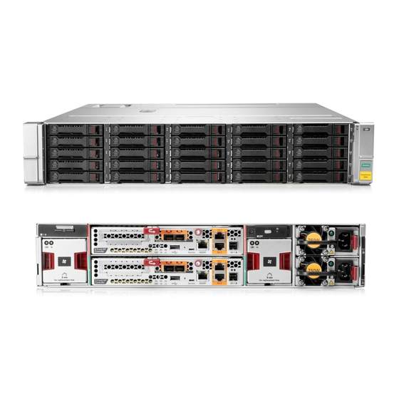
The array enclosure is available in either an LFF configuration with 12 drive bays, or an SFF configuration with 25 drive bays. There are four controller configurations available. Figure 1: HPE StoreVirtual 3200 Storage LFF front view 1. Disk drive locate UID 3. -
Page 9: Part Number
8. Power supply status LED 4. Fan module 9. Power supply module 5. Controller module Figure 4: HPE StoreVirtual 3200 Storage 1 GbE controller module (2 port) 6. Service port (Micro-B USB) 1. Controller locate UID 7. Management port (MGMT) 2. - Page 10 Figure 5: HPE StoreVirtual 3200 Storage 1 GbE controller module (4 port) 1. Controller locate UID 7. Service port (Micro-B USB) 2. Controller status LED 8. Management port (MGMT) 3. Controller fault LED 9. 1 GbE ports 4. USB type A port 10.
- Page 11 11. SAS data port to optional drive enclosure (DP-1) 6. Recovery/power button (See Recovery/Power button on page 12). Figure 8: HPE StoreVirtual 3200 Storage 8Gb/16 Gb Fibre Channel controller module (2 port) 1. 8 Gb/16 Gb Fibre Channel ports 7. Service port (Micro-B USB) 2.
-
Page 12: Recovery/Power Button
Recovery/Power button The recovery/power button is a recessed button that requires an unfolded paper clip or other small pointed device to press it. The recovery/power has these functions depending upon the state of the controller: Press the recovery/power button for one second: •... -
Page 13: Locating The Product Serial Number On The Hardware
Figure 11: HPE StoreVirtual 3000 drive enclosure rear view 1. Pullout tab with serial number label 10. System status LED 2. I/O module (slot 1) 11. Power supply status LED 3. I/O module (slot 2) 12. Power supply 1 4. I/O module status LED 13. -
Page 14: Locating The Product Serial Number In The Management Console
Figure 12: Pullout tab location Figure 13: Serial number label Locating the product serial number in the Management Console Procedure 1. From the main menu, select Storage System. 2. Select Storage System Report. The serial number is located in the Warranty Information section Locating the product serial number in the Management Console... -
Page 15: Operating The Storage System
Operating the storage system For information on using the HPE StoreVirtual Management Console, see the StoreVirtual Management Console online help or user guide. Powering on the storage system NOTE: There is no power switch on the enclosure. Power is applied to the enclosure immediately when connected to a live power source. - Page 16 Table 1: Front panel system status LEDs Indicator Display Description System status LED Green on Normal operation. Amber on Critical fault. Amber flashing Non-critical fault. Locate UID Normal operation. Blue on Location requested. Safe to power off. Blue flashing Location requested. Do not remove.
-
Page 17: Storage Controller Enclosure Controller Module Status Leds
Table 4: Disk drive status LEDs Blue UID LED Bicolor (green/amber) power or Description status LEDs No power or an inactive spare Green on Powered on, no I/O, no fault Green flicker Powered on, active I/O, no fault Amber on Fault Powered on, no I/O, predictive Amber flash... -
Page 18: Ethernet Led Statuses
Blue UID LED Green Amber status Description power LED Manually initiated locate, no fault, safe to remove Flash Manually initiated locate, no fault, do not remove Automatically initiated locate, fault, safe to remove Flash Automatically initiated locate, fault, do not remove Ethernet LED statuses The LED statuses described in the Ethernet Led statuses table behave the same way for the following... -
Page 19: External Sas Led Status
Green LED Amber LED Description Flicker Link at low speed with activity Flash Flash (opposite green LED) Location requested External SAS LED status Table 8: External SAS LED statuses Green LED Amber LED Description Fault or no power Link at high speed, no activity Flicker Link at high speed with activity No link or no cable connected... -
Page 20: Safely Rebooting A Storage Controller
Table 10: I/O module status LEDs Indicator Display Description 7-segment display Indicates the enclosure number or an error/warning code Data ports (DP-1, DP-2) Green on, amber off Link at high speed with no activity Green flashing, amber off Link at high speed with activity Green on, amber on Link at low speed with no activity Green flashing, amber on... - Page 21 Procedure 1. Fail over the storage controller a. On the StoreVirtual menu, select Storage Systems. a. On the navigation pane, select the storage system, and then select Actions > Fail over storage controller on the content pane. b. Select the storage controller from the list if more than one is listed. a.
-
Page 22: Adding Storage System Capacity
8. Apply power to the StoreVirtual storage system. Once the system is completely powered on, log on to the StoreVirtual Management Console as described in the HPE StoreVirtual 3200 Storage Installation Guide. Verifying the state of the new drives and enclosures Procedure 1. -
Page 23: Using The Storevirtual Management Console To Scale Up The Storage System
Using the StoreVirtual Management Console to scale up the storage system Prerequisites • Confirm that the disk and enclosures were added. • Determine that the health status of the enclosure is listed as Normal. Procedure 1. On the StoreVirtual menu, select Storage Systems. 2. - Page 24 3. When installing a disk drive, press firmly to make sure that the drive is fully seated in the drive bay before closing the latch handle. 4. Tiering guidelines: a. Two tiers of storage are supported. b. Each storage tier is configured separately. c.
-
Page 25: Adding A Drive Enclosure
Adding a drive enclosure Installing the rail kits Procedure 1. Identify the rack locations for the enclosures. 2. Loosen the back bracket on the standard rail kit to accommodate the enclosure. Attach the rear hold down brackets by sliding the tab with the arrow pointed forward (1) into the corresponding slot on the left and right side of the rear of the chassis. - Page 26 6. To engage the rail to the front of the rack, pull the rail towards the front of the rack until the spring hook snaps into place. NOTE: Make sure that the respective guide pins for the square or round hole rack align properly into the EIA column hole spacing.
-
Page 27: Installing The Enclosure
8. Secure the front of the rail to the front EIA column using the flat securing screw/guide pin (provided in the package) in the bottom screw position of the rail. Installing the enclosure CAUTION: Install disk drives in the enclosure only after mounting the enclosure in the rack. An enclosure with disk drives installed is too heavy to lift safely. -
Page 28: Adding Storevirtual 3200 Storage Systems
Adding StoreVirtual 3200 storage systems Adding StoreVirtual 3200 storage systems increases the available storage capacity and provides additional redundancy and reliability. Adding a new StoreVirtual 3200 storage system is limited to iSCSI configurations. Adding a new storage system to an existing configuration Prerequisites •... - Page 29 Procedure Install the new storage system following the instructions in the HPE StoreVirtual Storage System Installation Guide. Use the Configuration Setup to configure the storage system through the Network Configuration step. In the Continue Configuration window, click No Point the web browser to the management IP address that was assigned to one of the storage controllers during the network setup.
-
Page 30: Hpe Storevirtual Multi-Site San Design
Network design—Good network design is a critical part of configuring a Multi-Site SAN to ensure reliability, high availability, and performance. Typical Multi-Site SAN configurations comprise two sites for StoreVirtual 3200 storage and support multiple network designs. • Data replication level—To protect the data across sites, you must choose a data protection level. The data protection level must have a number of mirrors that is equal to the number of sites in the configuration. -
Page 31: Calculating Bandwidth
Single subnet—Hewlett Packard Enterprise recommends using a single subnet. • Adequate bandwidth between sites—Plan for the appropriate amount of bandwidth for each storage system between sites. For instance if each site contains one StoreVirtual 3200 storage system, then you need at least 100 MB/sec throughput between sites. •... -
Page 32: Managing The Network
The StoreVirtual 3200 has multiple configurations available, including iSCSI and Fibre Channel transport types. The StoreVirtual 3200 is a dual controller array. The two storage controllers communicate with each other over a private communication path called the StoreVirtual Inter-Communication Link. There are no customer- based management interactions with this path. -
Page 33: Network Configuration For Array Enclosure With 1 Gbe Controller Modules (Four Port)
Servers 1 GbE iSCSI SAN SV3200 Figure 14: Configuration using four 1 GbE ports and one switch Network configuration for array enclosure with 1 GbE controller modules (four port) All iSCSI, Remote Copy, and Management traffic are routed through these four ports. The 1 GbE ports are bonded together for redundancy and performance during the Configuration Setup procedure. -
Page 34: Network Configuration For Array Enclosure With 10 Gbe/10Gbase-T Controller Modules (Two Port)
1. Servers 2 . 1 GbE iSCSI SAN 3. Cloud connections 4. StoreVirtual storage system Network configuration for array enclosure with 10 GbE/10GBase-T controller modules (two port) All iSCSI, Remote Copy, and Management traffic are routed through these ports. The ports are bonded together for redundancy and performance during the Configuration Setup procedure. -
Page 35: Network Configuration For Array Enclosure With Fibre Channel Controller Modules (Two Port)
1. Servers 2 . 10 GbE/ 10GBase-T iSCSI SAN 3. Cloud connections 4. StoreVirtual storage system Network configuration for array enclosure with Fibre Channel controller modules (two port) The two Fibre Channel ports on each controller are used for data connections, and the two 1 GbE ports can be used for Management and Remote Copy. -
Page 36: Connecting The Storevirtual 3000 Drive Enclosure
Connecting the StoreVirtual 3000 drive enclosure Up to three HPE StoreVirtual 3000 drive enclosures can be connected to the array enclosure. The drive enclosures must be connected to the array enclosure using an asymmetric cabling scheme as shown in the following figures. -
Page 37: Connecting To Three Drive Enclosures
6. Connect DP-2 on the I/O module in slot 2 of the second drive enclosure to DP-1 on the I/O module in slot 2 of the first drive enclosure. Bonded interface configuration In an HPE StoreVirtual 3200 Storage System, the 1GbE and 10GbE/10GBase-T interfaces on both iSCSI and Fibre Channel Ethernet networks must be configured using bonded interfaces. Connecting to three drive enclosures... - Page 38 • Subnet mask Bond types The following types of bonding are supported with the HPE StoreVirtual 3200 Storage System: • ALB (default) – Can only be created between two or four interfaces that have the same speed. No additional network switch configuration is required. There can be a maximum of two 10GbE/10GBase-T interfaces or four 1GbE interfaces in the same bond.
- Page 39 1. Built-in 1G ports The two built-in 1G ports are bonded and share one subnet mask. Controller with a 1G GbE card 1. Option card 1G ports 2. Built-in 1G ports All four 1G ports are bonded and share one subnet mask. Controller with a 10GbE card 1.
-
Page 40: Multipathing With Iscsi Configurations
Controller with a 10GBase-T card 1. Option card 10GBase-T ports 2. Built-in 1G ports The 10GBase-T ports are bonded and share a subnet mask. The built-in 1G ports are not bonded. The 10GBase-T and built-in 1G ports cannot be used simultaneously. Controller with a Fibre Channel card 1. -
Page 41: Iscsi Multipathing Without Dsm Or Mem
• A total of four or eight IP addresses can be defined depending upon the number of ports. • A virtual IP address is configured. • The client must be enabled with multipathing so that it knows that the same disk is accessible from multiple paths. -
Page 42: Removing And Replacing Hardware Components
Removing and replacing hardware components This chapter describes procedures for removing and replacing hardware components. For general information about customer self repair (CSR), see Customer self repair (CSR). Customer self repair (CSR) Identifying the spare part number Parts have a nine-character spare part number on their label. If necessary, Hewlett Packard Enterprise Support can assist in identifying the correct spare part number. -
Page 43: Replaceable Parts List
Replaceable parts list NOTE: The spare part numbers listed were assigned at initial product release. For the latest updates, go to HTTP://PARTSURFER.HPE.COM/. Enter your product serial number or model number. Figure 23: Storage controller enclosure replaceable parts Table 13: Storage controller enclosure parts list Callout Description Spare part name... - Page 44 Callout Description Spare part name Spare part number CSR type Air guard Power distribution SPS-VRM Assembly 808276-001 module Power supply SPS-Power Supply 660183-001 Mandatory 750W 1U HEPB Enclosure Controller module SPS Controller Node 840213-001 Mandatory Assy (SFF/1GbE 2P) SPS Controller Node 840214-001 Mandatory Assy (LFF/ 1GbE 2P)
- Page 45 Callout Description Spare part name Spare part number CSR type HPE SV3000 600GB 832975-001 Mandatory 12G SAS 15K SFF HPE SV3000 300GB 832969-001 Mandatory 12G SAS 10K SFF HPE SV3000 600GB 832970-001 Mandatory 12G SAS 10K SFF HPE SV3000 900GB 832971-001 Mandatory 12G SAS 10K SFF...
- Page 46 HD to HD 3.0, to HD 3.0, 0.5 0.5 (not shown) 793444-001 Transceiver (not 16Gb FC SFP Mandatory shown) 793444-001 Transceiver (not HP 16Gb SFP+ SW 1- Mandatory shown) pack Commercial XCVR Transceiver (not SPS-SFP+,10G 456096-001 Mandatory shown) BLc,SR...
- Page 47 Callout Description Spare part name Spare part number CSR type Transceiver (not Assy, 10Gb SR SFP + 456096-001 Mandatory shown) Cable Transceiver (not 8Gb FC SFP AJ718-63001 Mandatory shown) Transceiver (not 8Gb Short Wave FC AJ718-63001 Mandatory shown) SFP+ 1 Pack Mandatory—You order the part directly from Hewlett Packard Enterprise and repair the product yourself.
- Page 48 Callout Description Spare part name Spare part number CSR type SPS Cage; LFF Hard 781531-001 Mandatory Disk Drive (HDD) 832029-001 Backplane PCA, SFF HDD Mandatory Backplane 832030-001 SPS PCA Backplane; Mandatory LFF HDD Air guard Power distribution SPS-VRM Assembly 808276-001 Mandatory module Power supply...
- Page 49 Callout Description Spare part name Spare part number CSR type HPE SV3000 600GB 832970-001 Mandatory 12G SAS 10K SFF HPE SV3000 900GB 832971-001 Mandatory 12G SAS 10K SFF HPE SV3000 1.2TB 832972-001 Mandatory 12G SAS 10K SFF HPE SV3000 1.8TB 832973-001 Mandatory 12G SAS 10K SFF...
-
Page 50: Warnings And Precautions
Callout Description Spare part name Spare part number CSR type HPE SV3000 600GB 832975-001 Mandatory 12G SAS 15K SFF HPE SV3000 400GB 851306-001 Mandatory 12G SAS 3.5in MU CC HPE SV3000 800GB 851307-001 Mandatory 12G SAS 3.5in MU CC HPE SV3000 3.2TB 851305-001 Mandatory 12G SAS 2.5in MU... -
Page 51: Equipment Symbols
Equipment symbols Symbol Description Warning Any enclosed surface or area of the To reduce the risk of injury from electrical equipment marked with these symbols shock hazards, do not open this enclosure. indicates the presence of electrical shock hazards. Enclosed area contains no operator serviceable parts. -
Page 52: Replacing A Disk Drive
1. Check the disk drive status LEDs to ensure that the drive has failed. For the location of the disk drive LEDs, see the Disk drive status LEDs table. 2. Check the disk drive status from the StoreVirtual 3200 Management Console. Navigate to the Disks section of the StoreVirtual Management Console. The Health tile on the Disks Overview window displays the disk status. -
Page 53: Installing A Disk Drive
Figure 26: SFF handle release button 2. Swing out the latch handle on the drive (1) and pull the drive out of the enclosure bay (2). Figure 27: LFF disk drive removal Figure 28: SFF disk drive removal Installing a disk drive CAUTION: To prevent improper cooling and thermal damage, operate the enclosure only when either a disk drive or a drive blank is installed in every bay. - Page 54 Figure 29: LFF disk drive blank NOTE: Removal of an SFF drive blank is similar to the example shown for the LFF drive blank. 2. Unlatch the handle by pressing the button on the disk drive. NOTE: Both LFF and SFF disk drives shown. Figure 30: LFF handle release button Figure 31: SFF handle release button 3.
-
Page 55: Verifying Disk Drive Operation
Figure 32: LFF disk drive Figure 33: SFF disk drive 4. Verify the status of the disk drive. For drive status, see Status LED descriptions. To view the status using the management software, log on to the StoreVirtual Management Console and navigate to the Disks section. -
Page 56: Replacing A Controller Module
• Fail over the storage controller from the Storage Systems pane in the StoreVirtual Management Console. See the HPE StoreVirtual 3200 Online Help for more information. NOTE: Ensure that the controller taking over all activities is fully functional. A controller replacement can be done online, but there is reduced system performance. -
Page 57: Installing A Controller Module
4. Pull the controller module (3) out of the enclosure using the controller module handle. Related reference Recovery/Power button on page 12 Installing a controller module Procedure IMPORTANT: Remove the battery from the failed controller. Batteries are not supplied with a replacement controller. -
Page 58: Completing The Controller Module Replacement
3. Fail back the storage controller. NOTE: You can locate failback in the StoreVirtual Management Console Storage Systems pane. See the HPE StoreVirtual 3200 Management Console Online Help for more information. Replacing a drive enclosure I/O module Verify I/O module failure Before replacing an I/O module, verify its status using one of the following methods: •... -
Page 59: Installing An I/O Module
3. Pull the I/O module (3) out of the enclosure using the I/O module handle. Installing an I/O module Procedure 1. Slide the replacement I/O module (1) into the enclosure and close the I/O module handle (2). 2. Tighten the captive retainer thumbscrew (3). 3. -
Page 60: Replacing A Power Supply Module
Replacing a power supply module Verifying power supply failure Procedure 1. Before replacing a power supply, check the power supply status LED to ensure that the power supply has failed. For the location of the power supply LEDs, see HPE StoreVirtual 3000 drive enclosure on page 12. -
Page 61: Installing A Power Supply
Installing a power supply Procedure 1. Slide the replacement power supply into the enclosure until it clicks into place. 2. Connect the power cable. Verifying power supply operation Procedure 1. Ensure that the power supply is operating properly by checking the status LED. For more information, see "Related reference". -
Page 62: Removing A Fan Module
For information on interpreting the status, see "Related reference". 2. Check the fan module heath in the Storage System Hardware Report available from the StoreVirtual Management Console. There is also an alert triggered when the fan module fails. Related reference Status LED descriptions on page 15 Removing a fan module Procedure... -
Page 63: Removing The Uid Health Module
Procedure 1. Press the system locate UID button on the rear of the enclosure and locate the UID from the StoreVirtual Management Console. 2. Press the system locate UID button the front of the enclosure, which turns on the system locate UID on the rear of the enclosure. - Page 64 Disconnect the UID health module cable from the backplane. Remove the UID health module retaining screw (1). Removing and replacing hardware components...
-
Page 65: Installing The Uid Health Module
10. Slide the UID health module (2) out of the enclosure while guiding the cable through the enclosure. CAUTION: The UID cable is firmly adhered to the chassis. Care should be take to peel the UID cable carefully off the enclosure chassis. Installing the UID health module Procedure 1. -
Page 66: Removing The Enclosure Backplane
CAUTION: This procedure requires removing the enclosure from the rack. Before removing the enclosure, ensure that data on the system is backed up. Back up data if necessary. Removing the enclosure backplane Procedure Disconnect all cables from the enclosure, including the power cables. Loosen the rear CTO hold-down bracket. - Page 67 11. Disconnect the following cables from the backplane: Number Cable Front UID health module Rear UID health module Power distribution unit Power supply Power supply 12. Remove the eight drive cage retaining screws. There are four to each side. Removing and replacing hardware components...
-
Page 68: Installing The Enclosure Backplane
NOTE: Depending on whether the drive cage is for LFF or SFF drives, the screws are in slightly different locations. 13. Slide the drive cage toward the front of the enclosure and lift free of the enclosure. 14. Remove the two screws attaching the back plane to the drive cage. 15. -
Page 69: Verifying Enclosure Backplane Operation
13. Install the fan modules. See Installing a fan module on page 62. 14. Install the disk drives in the same bays they were in the original enclosure. See Installing a disk drive. 15. Reconnect all cables to the enclosure, including the power cables. 16. -
Page 70: Verifying Fibre Channel Sfp Operation
Verifying Fibre Channel SFP operation Procedure 1. Reconnect the FC cable to the SFP and verify that the link status LED is solid green. For more information, see "Related reference". Related reference Status LED descriptions on page 15 Removing and replacing the fan control card cable assembly CAUTION: This procedure requires removing the enclosure from the rack. -
Page 71: Removing The Fan Control Card Cable Assembly
Removing the fan control card cable assembly NOTE: The fan control card cable assembly is between the backplane and fan module. Procedure 2. Remove fan control card cable from the backplane. 3. Remove the T-15 screw. 4. Slide the fan control card bracket sideways to free it from the retaining pins and lift it out. Remove the fan cable from the bracket. -
Page 72: Installing The Fan Control Card Assembly
NOTE: Slots are keyed and the fan cable assembly can only be installed one way. 8. Remove the fan cable. 1. Connector release 2. Keyed slots Installing the fan control card assembly Procedure Slide the connector to keyed slots. NOTE: Slots are keyed and the fan cable assembly can only be installed one way. -
Page 73: Removing And Replacing Ethernet Cables
Removing and replacing Ethernet cables NOTE: If the cable is malfunctioning, check the LED displays on the I/O module or controller Data port back panel. See Ethernet LED statuses on page 18 for LED status information. Procedure 1. Confirm that you have the correct ports for the cables being replaced. 2. - Page 74 CAUTION: Remove the battery cable gently. Do not allow the DIMM or battery to dangle by the cable. 4. Remove the battery from the controller module. Press the mounting tray tab on the side wall to release the catch/lock. 5. Remove the battery from the mounting tray. Removing and replacing hardware components...
-
Page 75: Installing The Cache Backup Battery
Installing the cache backup battery Procedure 1. Install the replacement battery in the mounting tray. 2. Install the battery and mounting tray in the controller module. Ensure the tab snaps into place to secure the mounting tray. Installing the cache backup battery... - Page 76 3. Connect the replacement battery cable to the DIMM. 4. Install the DIMM in the controller module by inserting the DIMM in the socket (1) and engaging the levers (2). Removing and replacing hardware components...
-
Page 77: Verifying Cache Backup Battery Operation
5. Install the controller module in the array enclosure. For more information, see Installing a controller module on page 57. Verifying cache backup battery operation Procedure 1. View the StoreVirtual Management Console to ensure the cache mode is normal. NOTE: The battery may need time to charge before it is fully functional. - Page 78 Slide the enclosure out of the rack and set it on a secure surface. Remove the storage controller enclosure from the rack. Pull the hood latch up and back (1 and 2), and lift the enclosure cover up and remove it (3). Remove both controller modules.
-
Page 79: Installing The Icl
10. Remove the ICL board from the mounting bracket by removing the four mounting screws (1) as displayed in the following figure. Installing the ICL Procedure 1. Install the replacement ICL board on the mounting bracket using the four mounting screws. 2. -
Page 80: Verifying Icl Operation
The StoreVirtual Migration Manager enables you to migrate data from a P4000 G2, StoreVirtual 4000, or StoreVirtual VSA system to a StoreVirtual 3200 system. For more information, see the StoreVirtual Migration Manager documentation (which includes a user guide and installation instructions) at http://www.hpe.com/ info/sv3200-docs. -
Page 81: Remote Support
Remote support Overview Hewlett Packard Enterprise Remote Support with STaTS monitors your StoreVirtual 3200 storage system and allows the storage system to proactively contact Hewlett Packard Enterprise if issues arise on the system. All major (a warning in the event log) and minor (an alert in the event log) hardware events generate an alert that is sent to the customer-specified user and to Hewlett Packard Enterprise Support. -
Page 82: Remote Support Settings
Figure 34: Edit customer information Remote Support settings Remote Support monitors your system and allows the system to proactively contact Hewlett Packard Enterprise if issues arise. Hewlett Packard Enterprise Remote Support page The Remote Support page allows you to view the level of remote support. Remote Support settings... - Page 83 Table 15: Remote Support settings Setting Description Remote support level Describes the level of support configured on the StoreVirtual appliance: • Passive (default) – Allows events to be sent out but does not permit inbound queries. • No support – No events are sent out and does not permit inbound queries (Remote Support is disabled).
-
Page 84: Configuring And Modifying Remote Support
Configuring and modifying Remote Support Procedure 1. From the StoreVirtual menu, select Support. 2. Click Edit on the Remote Support Settings page. 3. Enter or edit the appropriate information shown in Figure 35: Remote Support Settings page on page Figure 35: Remote Support Settings page Proxy settings The Proxy Settings page displays information about the proxy settings (if required) to connect to the target HPE server. - Page 85 Figure 36: Proxy Settings page The following table describes the proxy settings. Table 16: Edit proxy settings. Field Description Proxy required If the proxy is required, this option allows the use of a network proxy to access the Internet. Protocol Protocol used by the proxy server.
-
Page 86: Rsvs Alarms
Field Description Password Password required to access the proxy server. Confirm password Re-enter the password for verification RSvS alarms Remote Support via STaTS (RSvS) alarms help to identify any Remote Support-specific issues. Viewing RSvS alarms To access RSvS alarms, select Active Alarms from the StoreVirtual main menu. Table 17: RSvS alarm messages Alarm message Description... -
Page 87: Support Mode
NOTE: If you select No Support in the Remote support level field, no RSvS-specific alarms are displayed. Support mode The Target HPE server field on the Remote Support Settings page can only be changed when Support mode is on. To enable support mode: Procedure 1. -
Page 88: Troubleshooting
StoreVirtual 3200 Storage system results in the enclosure status as unknown Symptom Installing a 3PAR StoreServ disk enclosure into a StoreVirtual 3200 Storage system results in the enclosure status reporting unknown in the SVMC and via REST. Cause A 3PAR StoreServ enclosure is not compatible with the StoreVirtual array and should not be used. -
Page 89: Raid Array Remains Degraded After Hot Spares Rebuild
Cause The Windows host does not recover from the disconnection in time and loses all paths to the volume. Extend the time that the host continues to retry the connection by modifying the LinkDownTime registry key, so that it has enough time to recover the paths. LinkDownTime determines how long requests will be held in the device queue and retried if the connection to the target is lost. - Page 90 Action Procedure 1. You can ignore the information; the system will work as designed. The issue corrects itself once the failed controller is replaced. Troubleshooting...
-
Page 91: Websites
Websites General websites Hewlett Packard Enterprise Information Library www.hpe.com/info/EIL Single Point of Connectivity Knowledge (SPOCK) Storage www.hpe.com/storage/spock compatibility matrix Storage white papers and analyst reports www.hpe.com/storage/whitepapers For additional websites, see Support and other resources. Websites... -
Page 92: Support And Other Resources
IMPORTANT: Access to some updates might require product entitlement when accessed through the Hewlett Packard Enterprise Support Center. You must have an HP Passport set up with relevant entitlements. Customer self repair Hewlett Packard Enterprise customer self repair (CSR) programs allow you to repair your product. If a CSR part needs to be replaced, it will be shipped directly to you so that you can install it at your convenience. -
Page 93: Remote Support
For more information about CSR, contact your local service provider or go to the CSR website: http://www.hpe.com/support/selfrepair Remote support Remote support is available with supported devices as part of your warranty or contractual support agreement. It provides intelligent event diagnosis, and automatic, secure submission of hardware event notifications to Hewlett Packard Enterprise, which will initiate a fast and accurate resolution based on your product's service level. -
Page 94: Documentation Feedback
www.hpe.com/info/reach For Hewlett Packard Enterprise product environmental and safety information and compliance data, including RoHS and REACH, see: www.hpe.com/info/ecodata For Hewlett Packard Enterprise environmental information, including company programs, product recycling, and energy efficiency, see: www.hpe.com/info/environment Documentation feedback Hewlett Packard Enterprise is committed to providing documentation that meets your needs. To help us improve the documentation, send any errors, suggestions, or comments to Documentation Feedback (docsfeedback@hpe.com). -
Page 95: Warranty And Regulatory Information
Warranty and regulatory information For important safety, environmental, and regulatory information, see Safety and Compliance Information for Server, Storage, Power, Networking, and Rack Products, available at www.hpe.com/support/Safety- Compliance-EnterpriseProducts. Warranty information HPE ProLiant and x86 Servers and Options www.hpe.com/support/ProLiantServers-Warranties HPE Enterprise Servers www.hpe.com/support/EnterpriseServers-Warranties HPE Storage Products www.hpe.com/support/Storage-Warranties... -
Page 96: Turkey Rohs Material Content Declaration
• Belarus: • Kazakhstan: Manufacturing date: The manufacturing date is defined by the serial number. CCSYWWZZZZ (serial number format for this product) Valid date formats include: • YWW, where Y indicates the year counting from within each new decade, with 2000 as the starting point; for example, 238: 2 for 2002 and 38 for the week of September 9.