
Related Manuals for Fujitsu AOU48RLXFZ


Summary of Contents for Fujitsu AOU48RLXFZ
- Page 1 DTR_BMU001E_05 VD014E/06 DESIGN & TECHNICAL MANUAL Hybrid Flex Inverter System FUJITSU GENERAL LIMITED...
- Page 2 CONTENTS 1. GENERAL INFORMATION 2. MODEL SELECTION 3. OUTDOOR UNITS 4. INDOOR UNITS 5. CONTROL SYSTEM 6. SYSTEM DESIGN 7. OPTIONAL PARTS...
- Page 3 Hybrid Flex Inverter System 1. GENERAL INFORMATION DTR_BMU001E_03--CHAPTER01 2010.08.25...
- Page 4 CONTENTS 1. GENERAL INFORMATION 1. FEATURES OF SYSTEM ............. 01 - 01 1-1. HIGH EFFICIENCY & COMPACT ............. 01 - 01 1-2. FLEXIBLE DESIGN & EASY INSTALLATION .......... 01 - 02 1-3. CENTRAL CONTROL ................01 - 05 2. MODEL LINE UP ................01 - 07 2-1.
-
Page 5: Features Of System
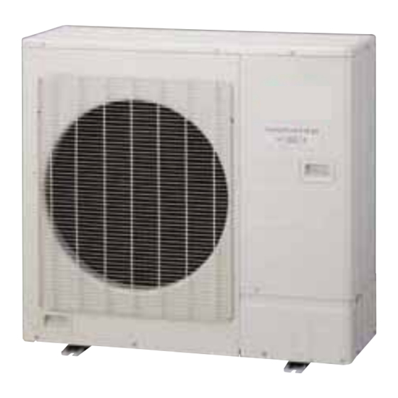
FEATURES OF SYSTEM 1-1. HIGH EFFICIENCY & COMPACT HIGH EFFICIENCY Adopting a large heat exchanger, high efficiency ventilation fan, DC twin rotary compressor, etc. realizes high efficiency operation. SEER:17.0 HSPF:9.8 Cooling Heating 3.89 15.0 16.0 17.0 SEER 10.0 HSPF TOP CLASS TOP CLASS COMPACT DESIGN Compact and lightweight outdoor unit is easy to carry in, it can be installed unnoticeably in various places. -
Page 6: Flexible Design & Easy Installation
1-2. FLEXIBLE DESIGN & EASY INSTALLATION FLEXIBLE DESIGN ● 4 types, 12models of indoor units can be selected ranging from 7000BTU to 24000BTU in capacity. Compact Cassette Slim Duct Compact Wall Mounted Wall Mounted ● Up to 8 indoor units can be connected to one outdoor unit. ●... - Page 7 EASY INSTALLATION ● Corresponding to diverse installation environments by use of branch connection system. Current model : 4 Rooms multi x 2 New model Branch box BRANCH BOX ● Branch box has an electronic expansion valve built-in, so it can control the refrigerant flow to each indoor unit.
-
Page 8: Installation Procedure
DECREASE OF INSTALLATION MISTAKE ● This operation allows the air conditioner to automatically check the status of the outdoor unit and check for wiring mistakes. Installation procedure Refrigerant piping and electrical wiring work All Flare connection Sealing test Vacuum process Refrigerant piping &... -
Page 9: Central Control
1-3. CENTRAL CONTROL Support comfort control system for the varied needs of the home and the condominium, etc. ● Central remote controller is connected directly to the branch box, making the installation process easier. ● Once the controller is connected, it can automatic register and display all the indoor units. CENTRAL REMOTE CONTROLLER (Option) Controllable 1 Multi system... - Page 10 VARIOUS OPERATION MODES SET BY REMOTE CONTROLLER Outdoor unit low noise operation ● Users can choose from 4 low noise levels, depending on the conditioning load factor installation environment. Heat load 100% Down Capacity 58dB Operating sound (time) Low noise operation Minimum heat (All) operation ●...
-
Page 11: Model Line Up
MODEL LINE UP 2-1. OUTDOOR UNIT LINE UP Capacity Connectable Model name indoor unit (BTU/h) 48000 AOU48RLXFZ 2 to 8 MODEL DESIGNATION Type Destination Model code Function Function Function Function Function AO : Outdoor unit U: FUJITSU (BTU/h) R: Heat... -
Page 12: Indoor Unit
Function Function Model code Type Destination L: Inverter F: Flexible R: Heat (BTU/h) AU: Cassette U: FUJITSU pump 7 (7000) AR: Duct 9 (9000) AS: Wall Mounted 12 (12000) 18 (18000) 24 (24000) - (01 - 08) - 1. GENERAL INFORMATION... -
Page 13: Controller
2-3. CONTROLLER LINE UP Indoor units Compact Type Model Compact Wall Cassette Slim Duct Wall mounted mounted Central remote controller UTY-DMMUM Wired Remote Controller UTY-RNNUM UTY-LNHUM Wireless Remote Controller AR-RAH1U IR Receiver Unit UTY-LRHUM Simple Remote Controller UTY-RSNUM : Accessory, : Optional, -: It is not possible to connect it. -
Page 14: Separation Tube
2-4. SEPARATION TUBE Separation tube Model : UTP-SX248A Liquid pipe Gas pipe 2-5. BRANCH BOX Primary type Secondary type Model : UTP-PU03A Model : UTP-PU03B - (01 - 10) - 1. GENERAL INFORMATION... -
Page 15: Others
2-6. OTHERS LINE UP Indoor units Outdoor Compact Type Model Compact Wall unit Cassette Slim Duct Wall mounted mounted Grill kit UTG-CCGF Air outlet shutter plate UTR-YDZB Insulation kit for high humidity UTZ-KXGC Fresh air intake kit UTZ-VXAA External control set UTD-ECS5A External connect kit UTY-XWZX... - Page 16 PARTS Grille kit Air outlet shutter plate Model : UTG-CCGF Models : UTR-YDZB For Compact Cassette type For Compact Cassette type Insulation kit for high humidity Fresh air intake kit Model : UTZ-KXGC Model : UTZ-VXAA Insulation For Compact Cassette type For Compact Cassette type External control set External connect kit...
-
Page 17: General Information
PARTS Apple catechin filter Apple catechin filter Model : UTR-FA16 Model : UTR-FA13-1 For Compact wall mounted type For Wall mounted type Ion deodorisation filter Ion deodorisation filter Model : UTR-FA16-2 Model : UTR-FA13-2 For Compact wall mounted type For Wall mounted type Communication kit Model : UTY-XCBXZ1 For Compact wall mounted type... -
Page 18: Model Selection
Hybrid Flex Inverter System 2. MODEL SELECTION DTR_BMU001E_04--CHAPTER02 2010.10.04... -
Page 19: Table Of Contents
CONTENTS 2. MODEL SELECTION 1. MODEL SELECTION PROCEDURE..........02 - 01 2. MODEL LINE UP ................02 - 02 2-1. OUTDOOR UNIT ..................02 - 02 2-2. INDOOR UNIT ................... 02 - 02 2-3. OPTIONAL PARTS..................02 - 02 3. MODEL SELECTION AND CAPACITY CALCULATION ..... 02 - 04 3-1. -
Page 20: Indoor Units
MODEL SELECTION PROCEDURE See 2-2.MODEL LINE UP(INDOOR UNIT) and Selection of indoor units 3-1. SELECTION PROCEDURE OF INDOOR UNIT AND OUTDOOR UNIT Selection of required optional parts See 2-3.MODEL LINE UP(OPTIONAL PARTS) ● Grill kit for Compact Cassette type See 2-3.MODEL LINE UP(OPTIONAL PARTS) Selection of Branch box Selection of Separation tube See 2-3.MODEL LINE UP(OPTIONAL PARTS) -
Page 21: Model Selection Procedure
MODEL LINE UP 2-1. OUTDOOR UNIT Capacity (BTU/h) Connectable indoor unit Model name Cooling Heating Number Capacity (%) 48000 54000 AOU48RLXFZ 2 to 8 80 to 130 2-2. INDOOR UNIT Rated capacity (BTU/h) Type Model name Remarks Cooling Heating 9000... - Page 22 OTHERS Items Model name Remarks Grill kit UTG-CCGF Air outlet shutter plate UTR-YDZB Insulation kit for high humidity UTZ-KXGC Fresh air intake kit UTZ-VXAA External control set UTD-ECS5A External connect kit UTY-XWZX External connect kit UTY-XWZXZ3 Refer to "7. OPTIONAL PARTS" External connect kit UTY-XWZXZ4 (For Base heater)
-
Page 23: Model Selection And Capacity Calculation
MODEL SELECTION AND CAPACITY CALCULATION 3-1. SELECTION PROCEDURE OF INDOOR UNIT AND OUTDOOR UNIT Please select indoor units and outdoor units and make the capacity of each indoor unit be larger than cooling and heating load. 1 Calculate heat load of each room 2 Tentative selection of indoor units 3 Calculate the total cooling capacity or heating capacity of indoor units The total cooling capacity or heating capacity of indoor units... -
Page 24: The Example Of Calculation
56000 x 0.960 = 53760 (A-4) x (A-6) temperature ∑(TC Calculate the Maximum capacity of outdoor unit Remark B-1 Outdoor unit model AOU48RLXFZ B-2 Rated capacity (TC 48000 Cooling B-3 Capacity change rate by temperature conditions 47.4 / 48.0 = 0.988 See Fig.1... - Page 25 42000 x 0.960 = 40320 (A-4) x (A-6) temperature ∑(TC Calculate the Maximum capacity of outdoor unit Remark B-1 Outdoor unit model AOU48RLXFZ B-2 Rated capacity (TC 48000 Cooling B-3 Capacity change rate by temperature conditions 47.4 / 48.0 = 0.988 See Fig.1...
- Page 26 Fig 1 Indoor temperature Indoor unit Outdoor 70°F DB 75°F DB 80°F DB 85°F DB 90°F DB connecting temperature 60°F WB 63°F WB 67°F WB 71°F WB 73°F WB capacity (%) (°F) ●●● ●●● ●●● ●●● ●●● ●●● ●●● ●●● ●●●...
- Page 27 Fig 2 i) Refer to 4. CAPACITY TABLE to find Y and Y using X and X ii) Calculate capacity of outdoor unit using following equation: Y=(Y ) / (X (X-X1) + Y (X, Y) Capacity ratio of indoor units to outdoor unit, X (%) Indoor temperature Indoor unit Outdoor...
-
Page 28: Heating Example
64800 x 1.10 = 71280 (A-4) x (A-6) temperature ∑(TC Calculate the Maximum capacity of outdoor unit Remark B-1 Outdoor unit model AOU48RLXFZ B-2 Rated capacity (TC 54000 Heating B-3 Capacity change rate by temperature conditions 59.7 / 54.0 = 1.106 See Fig.3... - Page 29 64800 x 1.10 = 71280 (A-4) x (A-6) temperature ∑(TC Calculate the Maximum capacity of outdoor unit Remark B-1 Outdoor unit model AOU48RLXFZ B-2 Rated capacity (TC 54000 Heating B-3 Capacity change rate by temperature conditions 55.3 / 54.0 = 1.024 See Fig.3...
- Page 30 Fig 3 Outdoor Indoor temperature Indoor unit temperature connecting 60°F DB 65°F DB 70°F DB 75°F DB 78°F DB capacity (%) °F °F ●●● ●●● ●●● ●●● ●●● ●●● ●●● ●●● ●●● ●●● ●●● ●●● ●●● ●●● ●●● ●●● ●●● ●●●...
- Page 31 Fig 4 i) Refer to 4. CAPACITY TABLE to find Y and Y using X and X ii) Calculate capacity of outdoor unit using following equation: Y=(Y ) / (X (X-X1) + Y (X, Y) Capacity ratio of indoor units to outdoor unit, X (%) Outdoor Indoor temperature Indoor unit...
-
Page 32: Capacity Table
CAPACITY TABLE 4-1. COOLING CAPACITY COOLING CAPACITY MODEL : AOU48RLXFZ Capacity in kBtu/h Indoor temperature Indoor unit Outdoor 70°F DB 75°F DB 80°F DB 85°F DB 90°F DB connecting temperature 60°F WB 63°F WB 67°F WB 71°F WB 73°F WB capacity (%) (°F) -
Page 33: Cooling Capacity
COOLING CAPACITY Capacity in kW Indoor temperature Indoor unit Outdoor 21.1°CDB 23.9°CDB 26.7°CDB 29.4°CDB 32.2°CDB connecting temperature 15.6°CWB 17.2°CWB 19.4°CWB 21.7°CWB 22.8°CWB capacity (%) (°C) -5.0 16.7 2.80 17.5 2.85 18.4 2.90 19.5 2.95 20.6 3.00 16.7 2.90 17.5 3.00 18.4 3.05 19.5... -
Page 34: Heating Capacity
4-2. HEATING CAPACITY HEATING CAPACITY MODEL : AOU48RLXFZ Capacity in kBtu/h Outdoor Indoor temperature Indoor unit temperature connecting 60°F DB 65°F DB 70°F DB 75°F DB 78°F DB capacity (%) °F °F 40.9 5.59 39.2 5.61 38.2 5.64 36.2 5.69 35.5... - Page 35 HEATING CAPACITY Capacity in kW Outdoor Indoor temperature Indoor unit temperature connecting 15.6°C DB 18.3°C DB 21.1°C DB 23.9°C DB 25.6°C DB capacity (%) °C °C -15.0 -16.1 12.0 5.59 11.5 5.61 11.2 5.64 10.6 5.69 10.4 5.67 -10.0 -11.1 15.0 5.66 14.7...
-
Page 36: Capacity Compensation Coefficient
CAPACITY COMPENSATION COEFFICIENT 5-1. COMPENSATION COEFFICIENT OF PIPE LENGTH The figures give the compensation coefficient of pipe length owing to installation position. CAPACITY CHANGE RATE BY MAIN PIPING LENGTH Change rate in capacity 16.4 32.8 49.2 65.6 82.0 98.4 114.8 131.2 147.6 164.0... -
Page 37: Compensation Coefficient Of Frosting / Defrosting
5-2. COMPENSATION COEFFICIENT OF FROSTING / DEFROSTING (HEATING OPERATION) To take the effects of accumulated frost and defrosting operation on heating capacity into consideration, the capacity of outdoor units should be corrected by compensation coefficient shown in the table below. Actual heating capacity = The value of capacity table x Capacity change rate by frosting CAPACITY CHANGE RATE BY FROSTING °FDB /... - Page 38 Hybrid Flex Inverter System 3. OUTDOOR UNIT & BRANCH BOX DTR_BMU001E_04--CHAPTER03 2010.10.04...
- Page 39 CONTENTS 3. OUTDOOR UNIT & BRANCH BOX 1. SPECIFICATIONS ................. 03 - 01 1-1. OUTDOOR UNIT ..................03 - 01 1-2. ENERGY EFFICIENCIES ................03 - 02 1-3. BRANCH BOX ................... 03 - 03 2. DIMENSIONS ................03 - 04 2-1.
- Page 40 SPECIFICATIONS 1-1. OUTDOOR UNIT Model name AOU48RLXFZ Power source 1ø 208/230V 60Hz Available Voltage Range 187-264V Number 2 to 8 Connectable indoor unit Capacity 80 to 130% Btu/h 48,000 Rated Cooling 14.1 Btu/h 51,100 Capacity Btu/h 54,000 Rated Heating 15.8...
- Page 41 1-2. ENERGY EFFICIENCIES non-Duct Duct Combination of indoor unit ASU12 x 4 ARU12 x 4 Btu/h 48,000 48,000 48,000 Capacity 14.1 14.1 14.1 Input power 5.19 5.52 5.35 Cooling Current 23.0 24.5 23.7 Btu/h/W 9.25 8.70 8.97 SEER 17.0 14.7 15.8 Btu/h 54,000...
- Page 42 1-3. BRANCH BOX Model name UTP-PU03A (Primary) UTP-PU03B (Secondary) Casing color Paintingless Paintingless Connectable indoor unit 1 to 3 Units 1 to 3 Units Max. combination Btu/h 62,000 62,000 Min. combination Btu/h 7,000 7,000 Power source 1ø 208/230V 60Hz 1ø 208/230V 60Hz Available voltage range 187-264V 187-264V...
- Page 43 DIMENSIONS 2-1. OUTDOOR UNIT Unit : inch (mm) MODEL : AOU48RLXFZ 6-17/32 (166) 25-19/32 (650) 6-1/16 (154) 1-7/8 (48) 1-13/32 (36) Top view 15/16 (24) 14-9/16 (370) 15/32 (12) 38-3/16 (970) ø1-3/32 (28): Cable port ø1-3/32 (28): Cable port 13/16 13/16 ø1-3/32 (28): Cable port...
- Page 44 2-2. BRANCH BOX MODELS : UTP-PU03A, UTP-PU03B 8-7/16 (214) Unit : inch (mm) 6-27/32 (174) 6-1/16 (154) 5-9/32 (134) 4-11/32 6-15/16 (176) (110) 8-1/2 (216) 10-3/32 (256) 18-15/32 (469) 17 (432) 3-11/32 2-11/16 (85) (68) 2-15/16 (75) 17-1/16 (433) 7-11/16 (195) Indoor unit side Ceiling hanging Outdoor unit side...
-
Page 45: Installation Space
INSTALLATION SPACE 3-1. OUTDOOR UNIT Caution ● The installation space shown in the following examples is based on an ambient temperature under cooling operation of 95 °F DB (35 °C DB) at the air intake of the outdoor unit. Provide more space around the air intake than shown in the examples if the ambient temperature exceeds 95 °F DB (35 °C DB) or if the thermal load of all of the outdoor units exceeds the capacity. - Page 46 3-1-2. MULTIPLE OUTDOOR UNIT INSTALLATION Provide at least 1inch (25mm) of space between the outdoor units if multiple units are ● installed. When routing the piping from the side of an outdoor unit, provide space for the piping. ● No more than 3 units must be installed side by side. ●...
-
Page 47: Horizontal Installation
3-2. BRANCH BOX The branch box can be installed onto the wall or hanging from the ceiling. ● The branch box can be installed and set horizontally or vertically. ● Provide a service access for maintenance and inspection purposes as shown in the figure ●... - Page 48 3-2-2. VERTICAL INSTALLATION A vertical installation can only be performed when mounting on the wall. ● (A vertical installation cannot be hung from the ceiling.) Be sure to install the control box so that the top side faces up. ● The positioning of the control box cannot be changed when performing a vertical installation.
-
Page 49: Refrigerant Circuit
REFRIGERANT CIRCUIT Branch box 1 (primary type) TH11 Outdoor unit Indoor unit 1 TH10 TH12 TH11 Indoor TH10 Strainer unit 2 HP-SW Strainer TH10 TH12 TH11 Indoor unit 3 EEV4 TH12 Strainer Comp EEV1 EEV3 ressor Strainer Strainer SCHEX Strainer EEV3 Strainer EEV3... -
Page 50: Symbol Description
SYMBOL DESCRIPTION Outdoor unit MARK DESCRIPTION Heat exchanger Oil separator SCHEX Sub-cool heat exchanger High pressure sensor HP-SW High pressure sensor switch Low pressure sensor 4-way valve 3-way valve EEV 1 Electric expansion valve 1 EEV 2 Electric expansion valve 2 Solenoid valve TH 1 Discharge temperature thermistor... - Page 51 WIRING DIAGRAM 5-1. OUTDOOR UNIT MODELS : AOU48RLXFZ - (03 - 12) - 3. OUTDOOR UNIT & BRANCH BOX...
- Page 52 5-2. BRANCH BOX MODEL : UTP-PU03A (Primary) MODEL : UTP-PU03B (Secondary) - (03 - 13) - 3. OUTDOOR UNIT & BRANCH BOX...
-
Page 53: Operation Range
OPERATION RANGE Operation range Operation mode Indoor unit Outdoor unit 64 to 90°F DB 23 to 115°F DB Cooling / Dry (18 to 32°C DB) (-5 to 46°C DB) R.H. 80% or less 60 to 88°F DB 5 to 75°F DB Heating (16 to 31°C DB) (-15 to 24°C DB) - Page 54 NOISE LEVEL CURVE MODEL : AOU48RLXFZ Cooling Heating N C -65 N C -65 N C -60 N C -60 N C -55 N C -55 N C -50 N C -50 N C -45 N C -45 N C -40...
- Page 55 SOUND LEVEL CHECK POINT Air flow Microphone 39-3/8in. (1 m) - (03 - 16) - 3. OUTDOOR UNIT & BRANCH BOX...
- Page 56 Voltage TOCA Limited Wiring Output AWG size AWG size Model name Length*2 (kW) Cross-section Cross-section 49/55 (ft.) AOU48RLXFZ 208/230 26.5 23.4 0.11 15/17 (m) 8-2. BRANCH BOX Rated Value Electric Characteristics Power Supply Full Load Characteristics Wiring Specifications *1 Power Cable...
- Page 57 SAFETY DEVICES 9-1. OUTDOOR UNIT Safety device AOU48RLXFZ Main PCB AC 250V 3.15A INV PCB DC 400V 5A Fuse AC 250V 10A Filter AC 250V 3.15A Protector Filter AC 500V 50A Overcurrent protection Compressor Protector Temperature protection Off : 239°F (115°C) On : 158°F (70°C)
- Page 58 Hybrid Flex Inverter System 4. INDOOR UNITS DTR_BMU001E_05--CHAPTER04 2010.11.12...
- Page 59 CONTENTS 4. INDOOR UNITS 1. FEATURES ................... 04 - 01 1-1. COMPACT CASSETTE TYPE ..............04 - 01 1-2. SLIM DUCT TYPE ................... 04 - 02 1-3. COMPACT WALL MOUNTED TYPE ............. 04 - 03 1-4. WALL MOUNTED TYPE ................ 04 - 04 2.
- Page 60 CONTENTS 4. INDOOR UNITS 9. NOISE LEVEL CURVE ..............04 - 46 9-1. COMPACT CASSETTE TYPE ..............04 - 46 9-2. SLIM DUCT TYPE ................... 04 - 48 9-3. COMPACT WALL MOUNTED TYPE ............04 - 50 9-4. WALL MOUNTED TYPE ................. 04 - 52 9-5.
-
Page 61: Features
FEATURES 1-1. COMPACT CASSETTE TYPE MODELS : AUU9RLF, AUU12RLF, AUU18RLF FEATURES Quiet quality 2-stage turbo fan Optimization of wing form (laminar High efficiency design by 2 stage structure wing type) and wing number (7 blades 2-stage turbo fan Previous turbo fan each) Wind A evenly spread air distribution across... -
Page 62: Slim Duct Type
1-2. SLIM DUCT TYPE MODELS : ARU9RLF, ARU12RLF, ARU18RLF, ARU24RLF Slim design and wide range of static pressure for flexible installation. FEATURES Slim design Flexible installation This model is slim design, it can install at Ceiling concealed the place where a ceiling is narrow. Drain port Height 7-25/32 in. -
Page 63: Quiet Operation
1-3. COMPACT WALL MOUNTED TYPE MODELS : ASU7RLF, ASU9RLF, ASU12RLF Compact and Stylish design indoor unit FEATURES High density heat transfer tube Easy maintenance arrangement Removable & washable Ø5 Making the tube panel →5 Thin: Volume reduction of heat Dry operation exchanger: Dry operation removes moisture and keeps the air conditioner clean. - Page 64 1-4. WALL MOUNTED TYPE MODELS : ASU18RLF, ASU24RLF Simple & Elegant Appearance Design FEATURES Compact & Slim design 39-9/32in. (998 mm) “ Vertical airflow” provides powerful floor level heating ft.(m) 7 (2.1) (24/30) 3 (1) 10 (3) 20 (6) 30 (9) 40 (12) ft.(m) Outside air conditions: 35.6 Outsid...
- Page 65 SPECIFICATIONS 2-1. COMPACT CASSETTE TYPE Model name AUU9RLF AUU12RLF AUU18RLF Power source 1ø 208/230V 60Hz Available voltage range 187-264V Btu/h 9,000 12,000 18,000 Cooling Rated 2.64 3.51 5.28 Capacity Btu/h 10,200 13,500 20,000 Heating Rated 3.00 3.96 5.85 Moisture removal pints/h(l/h) 2.5 (1.2) 3.2 (1.5)
- Page 66 2-2. SLIM DUCT TYPE Model name ARU9RLF ARU12RLF ARU18RLF ARU24RLF Power source 1ø 208/230V 60Hz Available voltage range 187-264V Btu/h 9,000 12,000 18,000 24,000 Cooling Rated 2.64 3.51 5.28 7.02 Capacity Btu/h 10,200 13,500 20,000 27,000 Heating Rated 3.00 3.96 5.85 7.92 Moisture removal...
- Page 67 2-3. COMPACT WALL MOUNTED TYPE Model name ASU7RLF ASU9RLF ASU12RLF Power source 1ø 208/230V 60Hz Available voltage range 187-264V Btu/h 7,000 9,000 12,000 Cooling Rated 2.04 2.64 3.51 Capacity Btu/h 8,100 10,200 13,500 Heating Rated 2.37 3.00 3.96 Moisture removal pints/h(l/h) 1.7 (0.8) 2.7 (1.3)
-
Page 68: Wall Mounted Type
2-4. WALL MOUNTED TYPE Model name ASU18RLF ASU24RLF Power source 1ø 208/230V 60Hz Available voltage range 187-264V Btu/h 18,000 24,000 Cooling Rated 5.28 7.02 Capacity Btu/h 20,000 27,000 Heating Rated 5.85 7.92 Moisture removal pints/h(l/h) 5.3 (2.5) 5.9 (2.8) Power consumption Running current 0.32 0.53... - Page 69 ELECTRIC CHARACTERISTICS Power Supply Indoor Rated Voltage Input Power Type Model name ASU7RLF 208 / 230 0.18 / 0.17 15 / 15 0.14 / 0.13 Compact Wall Mounted ASU9RLF 208 / 230 0.20 / 0.19 17 / 17 0.16 / 0.15 ASU12RLF 208 / 230 0.25 / 0.24...
- Page 70 DIMENSIONS 4-1. COMPACT CASSETTE TYPE MODELS : AUU9RLF, AUU12RLF, AUU18RLF Unit : in. (mm) • Decoration panel mounting state 20-7/8 (530): Hanging bolt position 5-5/16 9-27/32 (250) (135) op view Be sure to leave maintenance space Maintenance space for future service at the designated position.
- Page 71 INSTALLATION PLACE Unit : in. (mm) Strong and durable ceiling 10-5/16 (262) or more 39-3/8 (1000) 39-3/8 (1000) or more or more 94-1/2 (2400) or more Obstruction Floor H (The maximum height from floor to ceiling) Unit: in. (mm) Model name AUU9 AUU12 AUU18...
-
Page 72: Slim Duct Type
4-2. SLIM DUCT TYPE MODELS : ARU9RLF, ARU12RLF Unit : in. (mm) 22-19/32 (574) 2 (51) View A Rear view (Drain hose) Drain port 3-15/16 (100) x 6 = 23-5/8 (600) 1-27/32 (47) 2-5/32 (55) 25-19/32 (650) 3-1/16 (78) 28-29/32 (734) 3-1/2 (89) 1-7/8 (48) 4-11/16 (119) - Page 73 MODELS : ARU18RLF Unit : in. (mm) 2 (51) 30-15/32 (774) Rear view View A (Drain hose) Drain port 1-27/32 (47) 3-15/16 (100) x 8 = 31-1/2 (800) 2-5/32 (55) 3-1/16 (78) 33-15/32 (850) 3-1/2 (89) 36-25/32 (934) 3-7/16 (87) 4-11/16 (119) Top view 6-9/16 (167)
- Page 74 MODELS : ARU24RLF Unit : in. (mm) 38-11/32 (974) 2 (51) View A Rear view (Drain hose) Drain port 3-15/16 (100) x 10 = 39-3/8 (1000) 1-27/32 (47) 2-5/32 (55) 3-1/16 (78) 41-11/32 (1050) 44-21/32 (1134) 3-1/2 (89) 4-11/16 (119) 3-7/16 (87) Top view 6-9/16 (167)
- Page 75 Unit : in. (mm) INSTALLATION PLACE 11-13/16 (300) or more Strong and durable ceiling 25/32 (20) or more Indoor unit Left Right side side 25/32 (20) or more 11-13/16 (300) 3-15/16 (100) Service access Ceiling or more or more Floor 13/32 (10) 13/32 (10) or less...
- Page 76 Unit : in. (mm) MAINTENANCE SPACE Provide a service access for inspection purposes as shown below. Do not place any wiring or illumination in the service space, as they will impede service. Service access Unit Control 11-13/16 (300) or more Service space - (04 - 16) - 4.
-
Page 77: Compact Wall Mounted Type
4-3. COMPACT WALL MOUNTED TYPE MODELS : AS U7RLF, ASU9RLF, ASU12RLF Unit : in. (mm) 8-1/16 (205) : Installed state 31-3/32 (790) 8 (203) 5-1/2 (140) *1 5-23/32 (145) *1 *1: Vertical flap is downward Outline of unit 3-11/16 (94) 17-23/32 (450) 23/32 (18) 2-1/16 (52) - Page 78 INSTALLATION PLACE Unit : in. (mm) Outline of unit 1-7/8 (48) or more 2-1/16 (52) or more 3-15/16 (100) or more 2-3/4 (70) or more 59-1/16 (1500) or more - (04 - 18) - 4. INDOOR UNITS...
-
Page 79: Wall Mounted Type
4-4. WALL MOUNTED TYPE MODELS : ASU18RLF, ASU24RLF Unit : in. (mm) 39-9/32 (998) 20-15/32 (520) 8-31/32 23-7/32 (590) (228) 1 (25) 28-3/8 (721) 20-15/32 (520) 25/32 (20) 1-15/32 (37) Unit center 17-9/32 (439) 15-3/4 (400) 23/32 x 7/16 (18 x 11) hole 5/8 (16) 4-7/16 (113) 15-1/4 (387) - Page 80 INSTALLATION PLACE Unit : in. (mm) Outline of unit 2-1/16 (52) or more 2-3/32 (53) or more 3-5/32 (80) or more 4-23/32 (120) or more 59-1/16 (1500) or more - (04 - 20) - 4. INDOOR UNITS...
-
Page 81: Wiring Diagrams
WIRING DIAGRAMS 5-1. COMPACT CASSETTE TYPE MODELS : AUU9RLF, AUU12RLF, AUU18RLF - (04 - 21) - 4. INDOOR UNITS... -
Page 82: Slim Duct Type
5-2. SLIM DUCT TYPE MODELS : ARU9RLF, ARU12RLF, ARU18RLF, ARU24RLF - (04 - 22) - 4. INDOOR UNITS... -
Page 83: Compact Wall Mounted Type
5-3. COMPACT WALL MOUNTED TYPE MODELS : AS U7RLF, ASU9RLF, ASU12RLF - (04 - 23) - 4. INDOOR UNITS... -
Page 84: Wall Mounted Type
5-4. WALL MOUNTED TYPE MODELS : AS U18RLF, ASU24RLF - (04 - 24) - 4. INDOOR UNITS... -
Page 85: Air Velocity And Temperature Distributions
AIR VELOCITY AND TEMPERATURE DISTRIBUTIONS 6-1. COMPACT CASSETTE TYPE Conditions Fan speed : High Operation mode : FAN MODEL : AUU9RLF Air velocity distribution Top view Vertical flap : Up (ft.) Unit : ft./s (m/s) 1 (0.25) 2 (0.5) 3 (1.0) 7 (2.0) 3 (1.0) 7 (2.0) - Page 86 Note: Reference data Conditions Fan speed : High Operation mode : Heating Air velocity distribution Vertical flap: Downward (4Way) Side view Vertical flap : Down (ft.) Unit : ft./s (m/s) 7 (2.0) 7 (2.0) 5 (1.5) 5 (1.5) 3 (1.0) 3 (1.0) 2 (0.5) 2 (0.5)
- Page 87 Conditions Fan speed : High Operation mode : FAN MODEL : AUU12RLF Air velocity distribution Top view Vertical flap : Up (ft.) Unit : ft./s (m/s) 1 (0.25) 2 (0.5) 3 (1.0) 7 (2.0) 7 (2.0) 3 (1.0) 1 (0.25) 2 (0.5) 2 (0.5) 1 (0.25)
- Page 88 Note: Reference data Conditions Fan speed : High Operation mode : Heating Vertical flap: Downward (4Way) Air velocity distribution (ft.) Unit : ft./s (m/s) 5 (1.5) 5 (1.5) 3 (1.0) 3 (1.0) 2 (0.5) 2 (0.5) 1 (0.25) 1 (0.25) (ft.) Air temperature distribution (ft.)
- Page 89 Conditions Fan speed : High Operation mode : FAN MODEL : AUU18RLF Air velocity distribution Top view Vertical flap : Up (ft.) Unit : ft./s (m/s) 1 (0.25) 2 (0.5) 3 (1.0) 7 (2.0) 7 (2.0) 1 (0.25) 2 (0.5) 3 (1.0) 2 (0.5) 3 (1.0)
- Page 90 Note: Reference data Conditions Fan speed : High Operation mode : Heating Air velocity distribution Vertical flap: Downward (4Way) (ft.) Unit : ft./s (m/s) 7 (2.0) 7 (2.0) 5 (1.5) 5 (1.5) 3 (1.0) 3 (1.0) 2 (0.5) 2 (0.5) 1 (0.25) 1 (0.25) (ft.)
-
Page 91: Compact Wall Mounted Type
6-2. COMPACT WALL MOUNTED TYPE Conditions MODELS : AS U7RLF Fan speed : High Operation mode : Fan Unit : ft./s (m/s) (ft.) Top view Vertical flap : Up 2 (0.5) 7 (2.0) 3 (1.0) Horizontal flap : Center (ft.) (ft.) 7 (2.0) Top view... - Page 92 Conditions MODELS : AS U9RLF Fan speed : High Operation mode : Fan Unit : ft./s (m/s) (ft.) Top view Vertical flap : Up 7 (2.0) 3 (1.0) 2 (0.5) Horizontal flap : Center (ft.) (ft.) 7 (2.0) Top view 2 (0.5) 3 (1.0) Vertical flap : Up...
- Page 93 Conditions MODELS : AS U12RLF Fan speed : High Operation mode : Fan Unit : ft./s (m/s) (ft.) Top view Vertical flap : Up 7 (2.0) 3 (1.0) 2 (0.5) Horizontal flap : Center (ft.) (ft.) 7 (2.0) Top view 2 (0.5) 3 (1.0) Vertical flap : Up...
-
Page 94: Wall Mounted Type
6-3. WALL MOUNTED TYPE Conditions MODEL : ASU18RLF Fan speed : High Operation mode : Fan (ft.) Unit : ft./s (m/s) Top view Vertical flap : Up 3 (1.0) 7 (2.0) 2 (0.5) Horizontal flap : Center (ft.) (ft.) Unit : ft./s (m/s) 2 (0.5) 7 (2.0) Top view... - Page 95 Conditions MODEL : ASU24RLF Fan speed : High Operation mode : Fan (ft.) Unit : ft./s (m/s) Top view 2 (0.5) Vertical flap : Up 7 (2.0) 3 (1.0) Horizontal flap : Center (ft.) (ft.) Unit : ft./s (m/s) 2 (0.5) 7 (2.0) 3 (1.0) Top view...
-
Page 96: Fan Performance Curve
FAN PERFORMANCE CURVE 7-1. SLIM DUCT TYPE MODEL : ARU9RLF 0.44 (110) SP mode09 0.40 (100) upper limit Hi (SP mode09) 0.36 (90) 0.32 (80) Quiet (SP mode09) 0.28 (70) SP mode09 0.24 (60) lower limit 0.20 (50) Normal SP Hi (Normal SP) upper limit 0.16 (40) - Page 97 Cooling 60.8 (16) 59.0 (15) Capacity 57.2 (14) 55.4 (13) 53.6 (12) Outdoor temperature 51.8 (11) 50.0 (10) (300) (400) (500) (600) (700) (800) Air Flow [CFM (m /h)] Heating 113.0 (45) Capacity 111.2 (44) 109.4 (43) 107.6 (42) 105.8 (41) Outdoor temperature 104.0 (40) 102.2 (39)
- Page 98 MODEL : ARU12RLF 0.44 (110) Hi (SP mode09) SP mode09 0.40 (100) upper limit 0.36 (90) 0.32 (80) 0.28 (70) Quiet (SP mode09) 0.24 (60) SP mode09 lower limit Normal SP 0.20 (50) upper limit Hi (Normal SP) 0.16 (40) Quiet (Normal SP) 0.12 (30)
- Page 99 Cooling 60.8 (16) 59.0 (15) Capacity 57.2 (14) 55.4 (13) 53.6 (12) Outdoor temperature 51.8 (11) 50.0 (10) (300) (400) (500) (600) (700) (800) Air Flow [CFM (m /h)] Heating 113.0 (45) Capacity 111.2 (44) 109.4 (43) 107.6 (42) Outdoor temperature 105.8 (41) 104.0 (40) 102.2 (39)
- Page 100 MODEL : ARU18RLF 0.44 (110) Hi (SP mode09) SP mode09 0.40 (100) upper limit 0.36 (90) Quiet 0.32 (80) (SP mode09) 0.28 (70) SP mode09 0.24 (60) lower limit Normal SP 0.20 (50) upper limit Quiet 0.16 (40) (Normal SP) Hi (Normal SP) 0.12 (30) SP mode00...
- Page 101 Cooling 60.8 (16) Capacity 59.0 (15) 57.2 (14) 55.4 (13) 53.6 (12) Outdoor temperature 51.8 (11) 50.0 (10) (600) (700) (800) (900) (1000) (1100) (1200) Air Flow [CFM (m /h)] Heating 113.0 (45) Capacity 111.2 (44) 109.4 (43) 107.6 (42) 105.8 (41) Outdoor temperature 104.0 (40)
- Page 102 MODEL : ARU24RLF 0.32 (80) SP mode05 0.28 (70) upper limit Hi (SP mode05) Quiet 0.24 (60) (SP mode05) Hi (Normal SP) 0.20 (50) Normal SP upper limit 0.16 (40) Quiet 0.12 (30) (Normal SP) 0.08 (20) SP mode00 upper limit SP mode05 lower limit 0.04 (10)
- Page 103 Cooling 60.8 (16) Capacity 59.0 (15) 57.2 (14) 55.4 (13) 53.6 (12) Outdoor temperature 51.8 (11) 50.0 (10) (800) (900) (1000) (1100) (1200) (1300) (1400) (1500) (1600) Air Flow [CFM (m /h)] Heating 113.0 (45) 111.2 (44) Capacity 109.4 (43) 107.6 (42) 105.8 (41) 104.0 (40)
-
Page 104: Air Flow
AIR FLOW Air flow Operation Type Model speed mode High Cooling Quiet AUU9RLF High Heating Quiet High Cooling Quiet Compact AUU12RLF Cassette High Heating Quiet High Cooling Quiet AUU18RLF High Heating Quiet High Cooling Quiet ARU9RLF High Heating Quiet High Cooling Quiet ARU12RLF... - Page 105 Air flow Operation Type Model speed mode High Cooling Quiet ASU7RLF High Heating Quiet High Cooling Compact Quiet Wall ASU9RLF High Mounted Heating Quiet High Cooling Quiet ASU12RLF High Heating Quiet High Cooling Quiet ASU18RLF High Heating Quiet Wall Mounted High 1120 Cooling...
-
Page 106: Indoor Units
NOISE LEVEL CURVE 9-1. COMPACT CASSETTE TYPE MODEL : AUU9RLF Cooling Heating N C -65 N C -65 N C -60 N C -60 N C -55 N C -55 N C -50 N C -50 N C -45 H igh N C -45 H igh N C -40... - Page 107 MODEL : AUU18RLF Cooling Heating N C -65 N C -65 N C -60 N C -60 N C -55 N C -55 H igh N C -50 N C -50 H igh N C -45 N C -45 N C -40 N C -40 N C -35 N C -35...
-
Page 108: Slim Duct Type
9-2. SLIM DUCT TYPE MODEL : ARU9RLF Cooling Heating N C -65 N C -65 N C -60 N C -60 N C -55 N C -55 N C -50 N C -50 N C -45 N C -45 N C -40 N C -40 N C -35 N C -35... - Page 109 MODEL : ARU18RLF Cooling Heating N C -65 N C -65 N C -60 N C -60 N C -55 N C -55 N C -50 N C -50 N C -45 N C -45 N C -40 N C -40 N C -35 H igh N C -35...
-
Page 110: Compact Wall Mounted Type
9-3. COMPACT WALL MOUNTED TYPE MODEL : AS U7RLF Cooling Heating N C -65 N C -65 N C -60 N C -60 N C -55 N C -55 N C -50 N C -50 N C -45 N C -45 H igh H igh N C -40... - Page 111 MODEL : AS U12RLF Cooling Heating N C -65 N C -65 N C -60 N C -60 N C -55 N C -55 N C -50 N C -50 H igh N C -45 N C -45 H igh N C -40 N C -40 N C -35...
-
Page 112: Wall Mounted Type
9-4. WALL MOUNTED TYPE MODEL : AS U18RLF Cooling Heating N C -65 N C -65 N C -60 N C -60 N C -55 N C -55 H igh N C -50 N C -50 H igh N C -45 N C -45 N C -40 N C -40... -
Page 113: Sound Level Check Point
9-5. SOUND LEVEL CHECK POINT COMPACT CASSETTE TYPE Microphone Microphone - (04 - 53) - 4. INDOOR UNITS... - Page 114 SLIM DUCT TYPE 6ft. 6-3/4in. (2m) 3ft. 3-3/8in. (1m) Measuring duct Measuring duct Microphone Microphone Center Center Side view Front view COMPACT WALL MOUNTED AND WALL MOUNTED TYPE Microphone Microphone 3ft. 3-3/8in. (1m) - (04 - 54) - 4. INDOOR UNITS...
-
Page 115: Safety Devices
SAFETY DEVICES Fan motor Terminal Float Model and type PCB fuse thermal thermal fuse switch protector 266 + 63°F AUU9RLF - 48°F ○ Compact Cassette AUU12RLF 250V 3.15A ― (130 +17°C AUU18RLF -9°C) ARU9RLF 275 ± 59°F ARU12RLF ○ Slim Duct 250V 3.15A ―... -
Page 116: Control System
Hybrid Flex Inverter System 5. CONTROL SYSTEM DTR_BMU001E_04--CHAPTER05 2010.10.04... -
Page 117: System Design
CONTENTS 5. CONTROL SYSTEM 1. CONTROL SYSTEM..............05 - 01 1-1. LINE UP OF CONTROLLERS ............... 05 - 01 1-2. CONTROL SYSTEM DESIGN ............... 05 - 02 1-3. SYSTEM CONFIGURATION EXAMPLES ..........05 - 03 1-4. CONTROL EQUIPMENT DESIGN LIMITATION ........05 - 05 2. -
Page 118: Control System
CONTROL SYSTEM 1-1. LINE UP OF CONTROLLERS FEATURES OF CONTROL SYSTEM Air Conditioning Central Control Air Conditioning Individual Control Central controller specially designs for centralized control. A range of remote controllers suitable for range of individual control situations, using various built-in timers. Central Remote Wired Remote Controller... -
Page 119: Control System Design
1-2. CONTROL SYSTEM DESIGN ADVANCED INTEGRATED CONTROL SYSTEM Air Conditioning Air Conditioning System Central Control Individual Control Outdoor Unit Branch box (Primary) Wired Remote Controller UTY-RNNUM Central Remote Controller UTY-DMMUM Simple Remote Controller UTY-RSNUM Branch box (Secondary 1) Wireless Remote Controller Transmission line UTY-LNHUM AR-RAH1U... -
Page 120: System Configuration Examples
1-3. SYSTEM CONFIGURATION EXAMPLES INDIVIDUAL CONTROL Wired Remote Controller ● Wired, simple, and wireless remote controllers can Branch box Branch box Branch box be used jointly. (Primary) (Secondary 1) (Secondary 2) ● Two remote controllers can be connected with single indoor unit. - Page 121 INDOOR UNIT TYPE AND THE APPLICABLE CONTROL METHOD Indoor units Compact Type Model Compact Wall Slim Duct Wall Cassette Mounted Mounted Central Remote Controller UTY-DMMUM Wired Remote Controller UTY-RNNUM UTY-LNHUM – – Wireless Remote Controller AR-RAH1U – – – IR Receiver Unit UTY-LRHUM –...
-
Page 122: Control Equipment Design Limitation
1-4. CONTROL EQUIPMENT DESIGN LIMITATION Model The number that can be connected Central Central Remote Controller UTY-DMMUM 1 / Multi system Controller UTY-LNHUM Wireless Remote Controller AR-RAH1U Controller Individual Wired Remote Controller UTY-RNNUM Controller 2 / Indoor unit Simple Remote Controller UTY-RSNUM IR Receiver Unit UTY-LRHUM... -
Page 123: Control Units
CONTROL UNITS The following types of controllers are available with the FUJITSU GENERAL LIMITED Hybrid Flex Inverter System : Central Remote Controller Wired Remote Controller Simple Remote Controller Wireless Remote Controller IR Receiver Unit Central Control Central Remote Controller Individual Control... -
Page 124: Central Remote Controller
2-1. CENTRAL REMOTE CONTROLLER MODEL : UTY - DMMUM ● Large and full-dot liquid crystal screen ● Screen with backlight can be seen even in the dark ● Wide and large keys easy to press, user-intuitive arrow key FEATURES Central & Individual Control Batched control of up to 8 indoor units. -
Page 125: Main Functions
MAIN FUNCTIONS Outdoor unit low noise operation ● Users can choose from 4 low noise levels, depending on the conditioning load factor installation environment. Heat load 100% Down Capacity 58dB Operating sound (time) Low noise operation Minimum heat (All) operation ●... - Page 126 FUNCTIONS 1 Display panel (with backlight) 6 Screen switch button (Right) 2 Screen switch button (Left) 7 Power indicator 3 Menu button 8 On / Off button 4 Cancel button 9 Enter button 5 Cursor button ELECTRICAL WIRING Example: Wiring diagram when 3 units of branch boxes are connected Branch box Branch box Branch box...
- Page 127 INSTALLATION 1) Remove the insulation of the remote controller cable. 55 (2-5/32) 45 (1-25/32) 30 (1-3/16) Unit : mm (in.) 8 (5/16) 8 (5/16) 1. 12V (Red) (5/16) 2. Signal (White) 3. COM (Black) 2) Insert the flat-blade screwdriver and remove the front case and rear case by twisting it slightly.
- Page 128 5) Connect the cable to the terminals on the front case. Fix the cable together with the sheath with the binder. Cut off the excess binder. Tightening torque Terminal screw 0.8 to 1.2N • m (7 to 10 lbf • in) Binder 1.
- Page 129 DIMENSIONS Unit : in. (mm) 1-3/16 1-5/16 (30) (33.5) 27/32 29/32 (21.3) 4-23/32 (120) (23) 11/32 (9) 3/16 (4.5) Front View Side View Rear View PACKING LIST Name and shape Quantity Application For connecting the remote controller Remote controller cable For installing the remote controller Screw (M4 x 16mm)
-
Page 130: Wired Remote Controller
2-2. WIRED REMOTE CONTROLLER MODEL : UTY - RNNUM FEATURES ● Various timer setup (ON / OFF / WEEKLY) are possible. ● Equipped with weekly timer as standard function. (Start / Stop function is twice per day for a week) ●... - Page 131 FUNCTIONS START/STOP button Pressed to start and stop operation. SET TEMP. button Display Selects the setting temperature. MODE button Selects the operating mode ( AUTO , COOL , DRY , , HEAT FAN button , MED Selects the fan speed ( AUTO , HIGH , QUIET Vertical air flow direction and swing button...
- Page 132 SYSTEM DIAGRAM 1 remote controller 2 remote controllers Indoor unit Indoor unit A , B , C : Remote controller cable. < < 1640ft (500m) ; B+C 1640ft (500m) Secon- Primary dary Remote controller Remote controllers ELECTRICAL WIRING 1 remote controller 2 remote controllers Indoor unit Indoor unit...
- Page 133 INSTALLATION Connection Pattern Note: Connection pattern is different according to type of Indoor unit. Indoor unit types Connection Pattern Compact Cassette type Pattern A Slim Duct type Compact Wall Mounted type Pattern B Wall Mounted type Pattern C Pattern A Connect the end of remote controller cable directly to the exclusive terminal block.
- Page 134 Pattern C 1) Modify the remote controller cable as per below methods. ● Use a tool to cut off the terminal on the end of the remote controller cable and then remove the insulation from the cut end of the cable as shown in Fig. ●...
- Page 135 PACKING LIST Name and shape Quantity Application Remote controller cable For connecting the remote controller [33ft(10m)] For installing the remote controller Screw (M4 x 16mm) For remote controller and remote controller cable Binder binding For connecting the remote controller cable to the Compact Connecting cable *1 wall mounted type and Wall mounted type indoor unit For installing the remote controller cable to the...
-
Page 136: Simple Remote Controller
2-3. SIMPLE REMOTE CONTROLLER MODEL : UTY - RSNUM FEATURES ● Easy operation. ● Built-in background light function. ● Easy installation with a slim shape with no bulge in the back. ● Error history.(Last 16 error codes can be accessed.) ●... - Page 137 FUNCTIONS START/STOP button Pressed to start and stop operation. Display background light Lights during operation. Operation lamp Lights during operation. FAN button Selects the fan speed ( AUTO , HIGH , MED , QUIET SET TEMP. button Selects the setting temperature. MODE button Selects the operating mode (AUTO , COOL...
- Page 138 ELECTRICAL WIRING 1 remote controller 2 remote controllers Indoor unit Indoor unit REMOTE REMOTE CONTROLLER CONTROLLER 1 2 3 1 2 3 1 (RED) : 12V 1 2 3 1 2 3 1 2 3 2 (WHITE) : Signal 3 (BLACK) : COM Secondary Primary Remote controller...
- Page 139 INSTALLATION Connection Pattern Note: Connection pattern is different according to type of Indoor unit. Indoor unit types Connection Pattern Compact Cassette type Pattern A Slim Duct type Compact Wall Mounted type Pattern B Wall Mounted type Pattern C Pattern A Connect the end of remote controller cable directly to the exclusive terminal block.
- Page 140 Pattern C 1) Modify the remote controller cable as per below methods. ● Use a tool to cut off the terminal on the end of the remote controller cable and then remove the insulation from the cut end of the cable as shown in Fig. ●...
- Page 141 PACKING LIST Name and shape Quantity Application For connecting the remote controller Remote controller cable [33ft(10m)] Screw For installing the remote controller (M4 x 16mm) For remote controller and remote controller cable Binder binding For connecting the remote controller cable to the Compact Connecting cable *1 wall mounted type and Wall mounted type indoor unit Screw *1...
-
Page 142: Wireless Remote Controller
2-4. WIRELESS REMOTE CONTROLLER MODEL : UTY - LNHUM / AR-RAH1U FEATURES ● Four kinds of timer setup (ON / OFF / PROGRAM / SLEEP) are possible. ● Can be used jointly with wired remote controllers . ● Easy to change custom code (4 patterns). Built-in timers Select from four different timer programs (On / Off / Program / Sleep). - Page 143 FUNCTIONS (UTY-LNHUM) MODE button Selects the operating mode (AUTO, COOL, DRY, FAN, HEAT). /Start / end R.C. custom code change. (Max 4 types) MIN.HEAT button Set temp. button ( ▲ / ▼ ) Set remote controller custom code buttons Sets the indoor temp./ Sets R.C. custom code. ECONOMY button SLEEP button Pressed to select sleep timer.
- Page 144 FUNCTIONS (AR-RAH1U) MODE button Selects the operating mode (AUTO, COOL, DRY, FAN, HEAT). /Start / end R.C. custom code change. (Max 4 types) MIN.HEAT button Set temp. button ( ▲ / ▼ ) Set remote controller custom code buttons Sets the indoor temp./ Sets R.C. custom code. ECONOMY button SLEEP button Pressed to select sleep timer.
- Page 145 SYSTEM DIAGRAM ● Control signal might not be recognized in following cases: (i) A curtain or a wall, etc. exists between transmitter and receiver. (ii) There is an instant-start type (inverter type, etc.) fluorescent lamp Signal receiver Signal transmitter in the room. window ●...
- Page 146 PACKING LIST Name and shape Quantity Application Installation manual Operating manual Use as remote controller holder Remote controller holder For remote controller holder installation Tapping screw Battery For remote controller [ 1.5V (R03 / AAA) ] SPECIFICATIONS Dimensions [H x W x D]: in. (mm) 6-11/16 (170) x 2-7/32 (56) x 3/4 (19) Weight : oz.
-
Page 147: Ir Receiver Unit
2-5. IR RECEIVER UNIT MODEL : UTY - LRHUM FEATURES Duct type indoor unit can be controlled with wireless remote controller if the IR receiver unit is used. FUNCTIONS Wireless remote controller IR Receiver OPERATION LAMP TIMER LAMP ECONOMY LAMP MANUAL AUTO SIGNAL RECEIVER Refer to 2-4.WIRELESS... - Page 148 ELECTRICAL WIRING Connected to CN13 of PCB CN13 Connection cable A 2-3/8in. x 4-3/4in. [ L = 16ft. ( 5m )] ...Standard accessory Connection cable B ( 60mm x 120mm ) Connection cable C [ L = 7-7/8in. ( 0.2m )] hole [ L = 33ft.
- Page 149 PACKING LIST Name and shape Quantity Application Installation manual Operating manual Cover For covering receiver unit Insulation For protecting PCB from dust Connection cable A For connecting PCB of indoor unit to receiver unit [16ft. (5m)] Connection cable B For connecting PCB of indoor unit to receiver unit [7-7/8in.
-
Page 150: Group Control Method
2-6. GROUP CONTROL METHOD REMOTE CONTROLLER GROUP Wired, Simple and Wireless Remote Controllers can be used jointly in the following combinations. Example of combination for "Remote controller group" - (05 - 33) - 5. CONTROL SYSTEM... -
Page 151: Comparison Table Of Controllers
2-7. COMPARISON TABLE OF CONTROLLERS LIST OF CONTROLLER FUNCTION Wireless Central Remote Wired Remote Simple Remote Item Remote Controller Controller Controller Controller UTY-LNHUM Model UTY-DMMUM UTY-RNNUM UTY-RSNUM AR-RAH1U Max. controllable indoor units ● ● ● ● Start/Stop ● ● ● ●... - Page 152 Hybrid Flex Inverter System 6. SYSTEM DESIGN DTR_BMU001E_04--CHAPTER06 2010.10.04...
- Page 153 CONTENTS 6. SYSTEM DESIGN 1. SYSTEM DESIGN ................. 06 - 01 1-1. SYSTEM OUTLINE ................06 - 01 1-2. REFRIGERANT SYSTEM ..............06 - 02 1-3. WIRING SYSTEM ................... 06 - 07 1-4. MOUNTING POSITION ................06 - 08 2. PIPING DESIGN ................06 - 10 2-1.
- Page 154 CONTENTS 6. SYSTEM DESIGN 5-10. DUCT STATIC PRESSURE SETTING ........... 06 - 80 6. CHECK RUN .................. 06 - 81 6-1. PRECAUTIONS & PREPARATION ............06 - 81 6-2. CHECK RUN CHECK ITEMS AND PROCEDURE ........ 06 - 83 6-3. CHECK RUN EXAMPLES ..............06 - 84 6-4.
-
Page 155: System Outline
SYSTEM DESIGN 1-1. SYSTEM OUTLINE Branch box 3 (Secondary) Indoor units Circuit breaker (over current) Earth leakage breaker Power supply Branch box 2 (Secondary) Circuit breaker (over current) Earth leakage breaker Power supply Branch box 1 (Primary) Circuit breaker (over current) Outdoor unit Earth leakage Central... -
Page 156: Refrigerant System
1-2. REFRIGERANT SYSTEM CONNECTABLE UNIT WITHIN 1 REFRIGERANT SYSTEM Unit Quantity Remarks Outdoor unit 1 unit Indoor unit 2 to Max. 8 units Connectable indoor unit capacity : 80% to 130% Branch box 1 to Max. 3 units One Branch box of primary type is always necessary Caution ●... - Page 157 EXAMPLE OF REFRIGERANT SYSTEM Example 1 (OK) Branch box 1 (Primary type) Outdoor unit Capacity ratio Indoor unit 2 Indoor unit 1 Total Connectable indoor Capacity Model capacity unit capacity (BTU/h) Judgement (BTU/h) (BTU/h) Min. Max. Outdoor unit AOU48 48000 48000 2 80% 3 130%...
- Page 158 Example 3 (OK) Branch box 2 Branch box 1 Outdoor unit (Secondary type) (Primary type) Indoor unit 3 Indoor unit 4 Indoor unit 1 Indoor unit 2 Indoor unit 5 Capacity ratio 119% Total Connectable indoor Capacity Model capacity unit capacity (BTU/h) Judgement (BTU/h) (BTU/h)
- Page 159 Example 5 (Not good) Branch box 1 (Primary type) Outdoor unit Indoor unit 1 Total Connectable indoor Capacity Model capacity unit capacity (BTU/h) Judgement (BTU/h) (BTU/h) Min. Max. Outdoor unit AOU48 48000 48000 2 80% 3 130% Not good → Because only one indoor unit is connected Indoor unit 1 ARU24...
- Page 160 Example 7 (Not good) Branch box 3 Branch box 2 Branch box 1 Outdoor unit (Secondary type) (Secondary type) (Primary type) Indoor unit 1 Indoor unit 2 Indoor unit 3 Indoor unit 4 Indoor unit 5 Indoor unit 6 Indoor unit 7 Capacity ratio 138% Total...
-
Page 161: Wiring System
1-3. WIRING SYSTEM MAXIMUM WIRING LENGTH Maximum wiring length Transmission line ft (m) Between outdoor unit and branch box 246 (75) Between branch box and indoor unit 246 (75) Between branch box and branch box 246 (75) Between branch box and Central remote controller 1640 (500) Between indoor unit and Wired R.C. -
Page 162: Mounting Position
1-4. MOUNTING POSITION OUTDOOR UNIT For the air conditioner to operate satisfactorily, install it as outlined in installation manual. Outdoor unit mounting position ● A position where satisfies the mounting space described in “3-3 Installation space". ● A position where the unit can be installed horizontally. ●... - Page 163 INDOOR UNIT For the air conditioner to operate satisfactorily, install it as outlined in installation manual. Indoor unit mounting position ● Decide the mounting position with the customer ● Install the unit level on a strong wall, floor, ceiling which is not subject to vibration. ●...
-
Page 164: Piping Design
PIPING DESIGN 2-1. IMPORTANT ITEMS WHEN USING NEW REFRIGERANT (R410A) R410A operates at higher pressure and has less solubility with mineral oil than traditional R22 refrigerant. Therefore, the lubricant and a part of pipe material are different. Some special tools are necessary. REFRIGERANT PIPING MATERIAL AND WALL THICKNESS It is necessary to use seamless copper tubes for refrigerant use. - Page 165 WORK FLOW (EXAMPLE) Preparations Prepare schedule of works ● Always check the refrigerant to be used. Refrigerant check ● Always use the specified refrigerant. ● Prepare materials / tools matched to the refrigerant. Operation chart preparation Start of work Indoor unit installation ●...
-
Page 166: Piping Limitation
2-2. PIPING LIMITATION LIMITATION Limitation Diagram ft (m) Total pipe length 377 (115) or less Total Between outdoor unit and the farthest indoor unit 230 (70) or less a + b + c + m Between outdoor unit and branch boxes 180 (55) or less a + b + c + d + e Total... - Page 167 CAUTION Keep the "piping limitation" for correct operation. Allowable height difference: If the height difference between the indoor unit and outdoor unit is larger than the allowable value: The pressure loss will be larger → Insufficient cooling and heating The refrigerant in liquid pipe will flush → Refrigerant flow noise generate at indoor unit The refrigerant oil will not return →...
-
Page 168: Pipe Size
2-3. PIPE SIZE PIPE DIAMETER, RECOMMENDED MATERIAL AND WALL THICKNESS Nominal Diameter (in) 1/4" 3/8" 1/2" 5/8" 3/4" Outside Diameter (mm) 6.35 9.52 12.70 15.88 19.05 Material JIS H3300 C1220T-O or equivalent *1 Wall Thickness *2 (mm) *1: Allowable tensile stress ≥ 33 (N/mm *2: Endurance pressure of the pipe must be 609 psi (4.2 MPa). - Page 169 Pipe size table "A" (Between outdoor unit and first separation tube) Outside diameter mm (in) Liquid pipe Gas pipe 9.52 (3/8") 15.88 (5/8") Pipe size table "B" (Between first separation tube and second separation tube) Outside diameter mm (in) Liquid pipe Gas pipe 9.52 (3/8") 15.88 (5/8")
-
Page 170: Selection Of Pipe Heat Insulating Material
2-4. SELECTION OF PIPE HEAT INSULATING MATERIAL ● Always insulate the refrigerant pipe to prevent condensation and water droplets by the refrigerant pipe. ● Decide the thickness of the heat insulating material by referring to the recommended minimum thickness in Table 1. (For installation condition T=90°F DB (32°C DB),humidity≤70%, humidity≤75%, humidity≤80%, humidity≤85%) ●... -
Page 171: Additional Charge Calculation
2-5. ADDITIONAL CHARGE CALCULATION ● The outdoor unit is charged refrigerant at the factory. ● Additional refrigerant required to be charged on site depending on pipe length. ● The additional refrigerant charge amount is calculated according to the following formula. ●... -
Page 172: Example Of Piping Design
2-6. EXAMPLE OF PIPING DESIGN EXAMPLE 1 Outdoor unit Separation Separation tube tube Branch box Branch box Branch box (7000Btu) (7000Btu) (7000Btu) (7000Btu) (7000Btu) (7000Btu) (7000Btu) (7000Btu) Indoor unit Indoor unit Indoor unit Indoor unit Indoor unit Indoor unit Indoor unit Indoor unit System configuration (Indoor units) - Page 173 Limitation check Example Limitation Diagram Judge ft (m) ft (m) Total pipe length Total Less than 377 (115) (80) Between outdoor unit and the farthest indoor unit a + b + c + m Less than 230 (70) (35) Between outdoor unit and branch boxes a + b + c + d + e Less than 180 (55) (37)
- Page 174 EXAMPLE 2 Outdoor unit Separation tube Branch box Branch box (18000Btu) (7000Btu) (7000Btu) (9000Btu) (7000Btu) (7000Btu) Indoor unit Indoor unit Indoor unit Indoor unit Indoor unit Indoor unit System configuration (Indoor units) Total Capacity (Btu) Model name ASU18 ASU7 ASU7 ASU9 ASU7 ASU7...
- Page 175 Limitation check Example Limitation Diagram Judge ft (m) ft (m) Total pipe length Total Less than 377 (115) (72) Between outdoor unit and the farthest indoor unit a + c + k Less than 230 (70) (37) Between outdoor unit and branch boxes a + c + d Less than 180 (55) (42)
- Page 176 EXAMPLE 3 Outdoor unit Branch box (24000Btu) (18000Btu) (7000Btu) Indoor unit Indoor unit Indoor unit System configuration (Indoor units) Total Capacity (Btu) Model name ASU24 ASU18 ASU7 49000 Capacity (Btu) 24000 18000 7000 Capacity ratio (Total indoor unit capacity) / (Total outdoor unit capacity) = (49000) / (48000) = 102.1% (Within 80% to 130%) Selection of separation tube Model...
- Page 177 Limitation check Example Limitation Diagram Judge ft (m) ft (m) Total pipe length Total Less than 377 (115) (84) Between outdoor unit and the farthest indoor unit c + h Less than 230 (70) (60) Between outdoor unit and branch box Less than 180 (55) (45) Total...
- Page 178 EXAMPLE 4 Outdoor unit Separation Separation tube tube Branch box Branch box Branch box (18000Btu) (18000Btu) (24000Btu) Indoor unit Indoor unit Indoor unit System configuration (Indoor units) Total Capacity (Btu) Model name ASU18 ASU18 ASU24 60000 Capacity (Btu) 18000 18000 24000 Capacity ratio (Total indoor unit capacity) / (Total outdoor unit capacity)
- Page 179 Limitation check Example Limitation Diagram Judge ft (m) ft (m) Total pipe length Total Less than 377 (115) (89) Between outdoor unit and the farthest indoor unit a + b + c + l Less than 230 (70) (55) Between outdoor unit and branch boxes a + b + c + d + e Less than 180 (55) (53)
-
Page 180: Installation
INSTALLATION 3-1. OUTDOOR UNIT OPENING A KNOCKOUT HOLE CAUTION ● Be careful not to deform or scratch the panel while opening the knock out holes. ● To protect the piping insulation after opening a knock out hole, remove any burrs from the edge of the hole. - Page 181 PIPE CONNECTION CAUTION ● Be sure to install the pipe against the port on the indoor unit and the outdoor unit correctly. If the centering is improper, the flare nut cannot be tightened smoothly. If the flare nut is forced to turn, the threads will be damaged.
- Page 182 Handling precautions for the valves ● Mounted part of Blank cap is sealed for protection. ● Fasten blank cap tightly after opening valves. Blank cap Tightening torque [mm (in.)] [N·m (lbf· ft)] 6.35 (1/4) 20 to 25 (14.8 to 18.4) 9.52 (3/8) 20 to 25 (14.8 to 18.4) 12.70 (1/2)
-
Page 183: Separation Tube
3-2. SEPARATION TUBE PIPE CONNECTION CAUTION ● Be sure to apply the pipe against the port on the indoor unit correctly. If the centering is improper, the flare nut cannot be tighten smoothly. If the flare nut is forced to turn, the threads will be damaged. - Page 184 Straight pipe length to branch box to branch box ● When connecting the main piping, do not bend it near the connection section. ● If the main pipe must be bent due to unavoidable circumstances, ensure that the linear section is 5-29/32inch (150mm) or more.
-
Page 185: Branch Box
3-3. BRANCH BOX INSTALLATION THE UNIT WARNING ● Perform installation in a location which can properly withstand the weight of the unit. Failure to install in a robust location or a faulty installment may cause the equipment to fall, a water leakage, electric shock or fire. - Page 186 (5) Remove the control box as shown in the figure, (6) Attach the control box to the main unit as and then change the positioning to the opposite shown in the figure. side. The lead wire Remove the control runs here box by lifting up and To the opposite side out through slots...
- Page 187 Fix the unit (When hanging from the ceiling) CAUTION ● Do not hang from the ceiling when performing a vertical installation. (1) Secure the hangers (accessories) with the screws (2 pieces, Ø 4 x 10mm, accessories). (4 places) Hanger (4 places) Screw (2) Secure the attachment section with the hanging bolt.
- Page 188 Fix the unit (For wall installation) <Horizontal installation> <Vertical installation> (1) Secure the hangers (accessories) with the (1) Secure the hangers (accessories) with the screws (2 pieces, Ø 4 x 10mm, accessories). screws (2 pieces, Ø 4 x 10mm, accessories). (4 places) (4 places) •...
- Page 189 PIPE CONNECTION (1) Detach the caps and plugs from the pipes. CAUTION ● Be sure to apply the pipe against the port on the unit correctly. If the centering is improper, the flare nut cannot be tightened smoothly. If the flare nut is forced to turn, the threads will be damaged. ●...
-
Page 190: Piping Insulation
PIPING INSULATION (1) Install the coupler heat insulation (large and small) and insulation (long and short) on each pipe as shown in the figures below. (2) Attach the butting surface with no gap to eliminate any gap between the insulations. (3) During the pipe insulation work, prevent air from getting inside the insulation with an adhesive tape (field supply). -
Page 191: Wiring Design
WIRING DESIGN 4-1. ELECTRICAL WIRING PRECAUTION FOR ELECTRICAL WIRING Regulation on wire diameter and selecting circuit breaker size differ from locality. Install in accordance with local rules and regulations. Warning ● Do not turn on the power until all installation work is complete. ●... - Page 192 WIRING SYSTEM LAYOUT For installation of the outdoor unit, branch boxes, and indoor units, follow the instructions in the installation manual for each unit. Branch box 3 (Secondary) Indoor units Circuit breaker (over current) Earth leakage breaker Power supply Branch box 2 (Secondary) Circuit breaker (over current)
-
Page 193: Power Supply Cable Wiring
Model cable size Remarks breaker MOCP 30mA 0.1sec or 208/230V 60Hz AOU48RLXFZ 8 AWG *1 26.5 A 40 A less 2Wire + ground ● Select cable size base on the value of MCA and MOCP. In the table of "3. OUTDOOR UNIT AND BRANCH BOX",example of wiring specification for outdoor unit is given. - Page 194 POWER SUPPLY CABLE WIRING Caution ● Except for EMERGENCY, never turn off main as well as sub breaker of the indoor units during operation. It will cause compressor failure as well as water leakage. ● First, stop the indoor unit by operating the control unit or external input device and then cut the breaker.
- Page 195 Example 3 (Branch box & indoor unit) Disconnect SW Indoor units Branch box Disconnect SW Branch box Disconnect SW Junction box Branch box Circuit breaker (over current) Earth leakage breaker Branch box - Indoor unit Power supply 1ø 208/230V 60Hz - (06 - 41) - 6.
- Page 196 WIRING RULES Example 1 (Not good) Power cable Branch box Power cable Do not connect the power cable directly to indoor units. Always supply power to indoor units from a branch box. - (06 - 42) - 6. SYSTEM DESIGN...
-
Page 197: Transmission Line
4-3. TRANSMISSION LINE TRANSMISSION WIRING SPECIFICATIONS Cable size Remarks ● Between Outdoor unit to Branch box 208/230V 60Hz ● Between Branch box to Branch box 14 AWG 3Wire + ground ● Between Branch box to Indoor unit Sheathed PVC cable ●... -
Page 198: Wiring Method
WIRING METHOD Practical transmission wiring method is shown below. Each terminal has to be connected the following rules. Example 1 Single-phase Power supply cable 208/230V 60Hz Max.26.5A Breaker1 Breaker1: Eeath leakage breaker Breaker2: Circuit breaker (over current) Breaker2 Outdoor unit Central remote controller Select the disconnect switch appropriately depending... - Page 199 WIRING RULES Example 1 (Not good) Transmission line Branch box (secondary) Do not connect outdoor unit to secondary type branch box. Always connect primary type branch box to outdoor unit. Example 2 (Not good) Transmission line Branch box (primary) Branch box (primary) Do not interconnect primary type branch boxes.
-
Page 200: Controller Cable Wiring
4-4. CONTROLLER CABLE WIRING WIRING SPECIFICATIONS Model type Connection to Wire Cable size Specification Central remote Remote controller Branch box 22 AWG controller cable Wired Remote Sheathed PVC cable Polar Indoor unit Controller 3core Remote controller 22 AWG cable Simple Remote Indoor unit Controller IR Receiver Unit... - Page 201 WIRING RULES Example 1 (good) Branch box (primary) Branch box 2 (secondary) Branch box 3 (secondary) Central remote controller line Central remote controller One Central remote controller can be connected any branch box in 1 refrigerant system. Example 2 (Not good) Branch box (primary) Branch box 2 (secondary) Branch box 3 (secondary)
- Page 202 Example 3 (Not good) Branch box (primary) Central remote controller line Central remote controller Central remote controller line Do not connect Central remote controller to outdoor unit or indoor unit. Always connect branch box to Central remote controller. Example 4 (Not good) Branch box (primary) Branch box 2 (secondary) Central remote...
- Page 203 Example 5 (Not good) Branch box (primary) Do not connect a wired remote controller or simple remote controller to branch box. Connect them to each indoor unit. Example 6 (Not good) Branch box 1 (primary) Branch box 2 (secondary) Wired Simple remote remote...
-
Page 204: Function Setting
FUNCTION SETTING 5-1. OUTDOOR UNIT SWITCH POSITION LED lamp 7 Segment LED Lamp LED981 LED982 POWER ERROR / MODE LED961 LED962 MODE / SELECT ENTER CHECK EXIT SW931 SW932 SW933 SW934 Outdoor unit printed circuit board Push button ● Set the functions of an outdoor unit with the push buttons (SW931, SW932 and SW933) while observing the 7-segment LED lamps (LED961 and LED962) on the printed circuit board. - Page 205 FUNCTION SETTING After verifying that the system is normally, press the MODE/EXIT button (SW931) once. LED961 LED962 LED961 LED962 Press the SELECT button (SW932), and display “F2” on the LED962. (Monitoring mode) (Setting mode) (Function mode) (Error history mode) LED961 LED962 LED961 LED962...
- Page 206 Again, referring to the Settings List shown below, press the SELECT button (SW932), and display the code number of the function you want to set on the LED962. Ex.) To select the Emergency Stop function LED961 LED962 LED961 LED962 Next, press the ENTER button (SW933), and confirm the selection of the function you want to set.
- Page 207 SETTINGS LIST LED961 LED962 Factory Setting Mode Setting Function Remarks CODE No. CODE No. setting Standard Use it when becoming cooling capacity shortage. Cooling High power mode 1 Use High power mode 2 when becoming capacity shift cooling capacity shortage in High power High power mode 2 mode 1.
-
Page 208: Indoor Unit (Setting By Jumper Wire)
5-2. INDOOR UNIT (setting by jumper wire) Note: This function is Slim Duct type only. SWITCH POSITION Slim Duct type JUMPER WIRE SETTING Drainage function setting (JM1) ( ...Factory setting) Drainage function Connect Valid Disconnect Invalid JM2 setting forbidden Fan delay setting (JM3) ( ...Factory setting) Fan delay Connect... -
Page 209: Indoor Unit (Setting By Wireless Remote Controller)
5-3. INDOOR UNIT (setting by wireless remote controller) This procedure changes to the function settings used to control the indoor unit according to ● the installation conditions. Incorrect settings can cause the indoor unit malfunction. After the power is turned on, perform the “FUNCTION SETTING” according to the ●... - Page 210 SWITCHING SELECTION OF FUNCTION SETTING MODE (2) Press and hold the “FAN” and the “ SET TEMP. ” buttons. While holding these 2 buttons, press the "RESET" button. SET TEMP. ( ) RESET Function setting mode display SELECTION AND CONFIRMATION OF CUSTOM CODE (3) Press the “...
- Page 211 BUTTON NAME AND FUNCTION ● During address setting mode, indoor unit reject the any operation command from remote controller. Function number Refer to FUNCTION DETAILS MODE button Setting number - Start the function setting mode Refer to FUNCTION DETAILS - Changes the display digits FAN button START/STOP button Transmits function setting...
- Page 212 FUNCTION SETTING (5) Press the “MODE” button to access the (6) Press the “ ” or the “ ” buttons to select function setting mode. the function number. Each time the “MODE” button is pressed, it switches between 1 unit and 10 units positions. Change degit (7) Press the FAN button to proceed to setting (8) Press the “...
- Page 213 COMPLETION OF FUNCTION SETTING MODE (11) Press the “RESET” button. RESET After pressing the RESET button, please set the custom code again if b,c,d setting. SETTING UP EACH INDOOR UNIT Repeat steps (1) through to (11). Steps (1) through to (4) and (11) only need to carried out if the custom code is different to the factory setting of “A”.
-
Page 214: Indoor Unit (Setting By Wired Remote Controller)
5-4. INDOOR UNIT (setting by wired remote controller) This procedure changes to the function settings used to control the indoor unit according to ● the installation conditions. Incorrect settings can cause the indoor unit malfunction. After the power is turned on, perform the “FUNCTION SETTING” according to the ●... - Page 215 SWITCHING SELECTION OF FUNCTION SETTING MODE 2) To activate the function setting mode, hold down the three buttons of SET TEMP. V, SET TEMP. Λ and FAN at the same time for 5 seconds or longer. Function setting mode initial display BUTTON NAME AND FUNCTION ●...
- Page 216 FUNCTION SETTING 3) Pressing the SET TIME < button or the SET TIME > button, to select the function number. Function number 4) Pressing the SET TEMP. V button or the SET TEMP. Λ button, to select the setting number. The display flashes during setting number selection.
- Page 217 COMPLETION OF FUNCTION SETTING MODE 6) To clear the function setting mode and return to the regular display, hold down the three buttons of SET TEMP. V, SET TEMP. Λ and FAN at the same time. Normal mode display * If no key entry is made for 60 seconds, even though none of the above buttons is pressed, the function setting mode will automatically be cleared.
-
Page 218: Indoor Unit (Setting By Simple Remote Controller)
5-5. INDOOR UNIT (setting by simple remote controller) This procedure changes to the function settings used to control the indoor unit according to ● the installation conditions. Incorrect settings can cause the indoor unit malfunction. After the power is turned on, perform the “FUNCTION SETTING” according to the ●... - Page 219 SWITCHING SELECTION OF FUNCTION SETTING MODE 2) To activate the function setting mode, hold down the three buttons of SET TEMP. , SET TEMP. and FAN at the same time for 5 seconds or longer. Function setting mode initial display BUTTON NAME AND FUNCTION ●...
-
Page 220: Function Details
FUNCTION SETTING 3) Press the FAN button so that the “Function number” display flashes. Then, press either the SET TEMP. button or the SET TEMP. button to set up the function number. Function number 4) Press the FAN button so that the “Setting number” display flashes. Then, press either the SET TEMP. - Page 221 COMPLETION OF FUNCTION SETTING MODE 6) Press the three buttons of SET TEMP. , SET TEMP. and FAN at the same time for 5 seconds or longer. The function setting mode will be cleared and the regular display will be restored. Normal mode display * If no key entry is made for 60 seconds, even though none of the above buttons is pressed, the function setting mode will automatically be cleared.
- Page 222 5-6. FUNCTION DETAILS Compact Compact wall Wall Functions Slim duct cassette mounted mounted 1) Filter sign 2) Ceiling height 3) Outlet directions 4) Static pressure 5) Cooler room temperature correction 6) Heater room temperature correction 7) Auto restart Indoor room temperature sensor switching function 9) Remote controller signal code 10) External input control...
- Page 223 4) Static pressure Select appropriate static pressure according to the installation conditions. ( ... Factory setting) Setting description Function number Setting value 0 in.WG (0 Pa) 0.04 in.WG (10 Pa) 0.08 in.WG (20 Pa) 0.12 in.WG (30 Pa) 0.16 in.WG (40 Pa) 0.20 in.WG (50 Pa) 0.24 in.WG (60 Pa) 0.28 in.WG (70 Pa)
- Page 224 8) Indoor room temperature sensor switching function (Only for Wired remote controller) The following settings are needed when use the control by Wired remote controller temperature sensor. ( ... Factory setting) Setting description Function number Setting value * If setting value is “00” : Room temperature is controlled by the indoor unit temperature sensor.
-
Page 225: Central Remote Controller
5-7. CENTRAL REMOTE CONTROLLER Memory backup setting Forbidden Forbidden Switch Forbidden Forbidden Forbidden SWITCH POSITION DIP Switch 1 2 3 4 5 6 Front case (back side) - (06 - 71) - 6. SYSTEM DESIGN... - Page 226 DIP SWITCH SETTING SW1 setting ● Memory backup setting Set to ON to use batteries for the memory backup. If batteries are not used, all of settings stored in memory will be deleted if there is a power failure. ( ...Factory setting) Memory backup Invalidity Validity...
- Page 227 SW5 setting forbidden ( ...Factory setting) Fixed at OFF Setting forbidden SW6 setting forbidden ( ...Factory setting) Fixed at OFF Setting forbidden - (06 - 73) - 6. SYSTEM DESIGN...
-
Page 228: Wired Remote Controller
5-8. WIRED REMOTE CONTROLLER Forbidden Dual remote controller setting Forbidden Switch 1 °F / °C switch Forbidden Memory backup setting * Do not use DIP Switch 2 SWITCH POSITION Wired remote controller Front case (back side) DIP Switch 2 DIP Switch 1 (All switches fixed at OFF) - (06 - 74) -... - Page 229 DIP SWITCH 1 SETTING SW1 setting forbidden ( ...Factory setting) Fixed at OFF Setting forbidden SW2 setting ● Dual remote controller setting Set the remote controller SW2 according to the following table. Indoor unit ( ...Factory setting) Secondary Primary unit Number Remote controller cable unit...
- Page 230 SW5 setting forbidden ( ...Factory setting) Fixed at OFF Setting forbidden SW6 setting ● Memory backup setting (Wired remote controller only) Set to ON to use batteries for the memory backup. If batteries are not used, all of settings stored in memory will be deleted if there is a power failure.
-
Page 231: Simple Remote Controller
5-9. SIMPLE REMOTE CONTROLLER Forbidden Dual remote controller setting °F / °C switch Switch Forbidden Forbidden Forbidden SWITCH POSITION Simple remote controller DIP Switch - (06 - 77) - 6. SYSTEM DESIGN... - Page 232 DIP SWITCH SETTING SW1 setting forbidden ( ...Factory setting) Fixed at OFF Setting forbidden SW2 setting ● Dual remote controller setting Set the remote controller SW2 according to the following table. Indoor unit ( ...Factory setting) Secondary Primary unit Number Remote controller cable unit 1 2 3...
- Page 233 SW5 setting forbidden ( ...Factory setting) Fixed at OFF Setting forbidden SW6 setting forbidden ( ...Factory setting) Fixed at OFF Setting forbidden - (06 - 79) - 6. SYSTEM DESIGN...
-
Page 234: Duct Static Pressure Setting
5-10. DUCT STATIC PRESSURE SETTING MODELS : ARU9RLF, ARU12RLF, ARU18RLF, ARU24RLF The air flow setting other than the default value of 0.1inWG (25 Pa) may be changed to the required external static pressure. Setting of the air flow can be changed with the wireless remote controller, wired remote controller, and simple remote controller. -
Page 235: Check Run
CHECK RUN This operation allows the air conditioner to automatically check the status of the outdoor unit and check for wiring mistakes. Installation mistakes and positions where errors are occurring are shown by the outdoor unit display indicators. * The Check run time is used only as a guide.This time differs depending on the surrounding temperature conditions. - Page 236 RESTRICTIONS APPLICABLE WHEN PERFORMING THE CHECK ● When the Check run starts, all indoor units connected to the outdoor unit will start to run automatically. During the Check run, you cannot check the operation of the indoor units separately. After the Check run, check the operation of the indoor units separately in normal operation.
-
Page 237: Check Run Check Items And Procedure
6-2. CHECK RUN CHECK ITEMS AND PROCEDURE Use the following procedure to perform the Check run. Check Item Procedure When an Error Occurs 1. Turn on 1.1 Check ▪ The power is on to the outdoor unit, When an error occurred power communi- connected branch boxes, and indoor units. - Page 238 6-3. CHECK RUN EXAMPLES : Wiring : Piping EXAMPLE1 When the number of piping is more than the number of wiring. Branch box 1 (Primary) Branch box 2 (Secondary) Branch box 3 (Secondary) INDOOR UNIT A INDOOR UNIT B INDOOR UNIT C INDOOR UNIT A INDOOR UNIT B INDOOR UNIT C...
- Page 239 EXAMPLE3 When connection destination does not match. Branch box 1 (Primary) Branch box 2 (Secondary) Branch box 3 (Secondary) INDOOR UNIT A INDOOR UNIT B INDOOR UNIT C INDOOR UNIT A INDOOR UNIT B INDOOR UNIT C INDOOR UNIT A INDOOR UNIT B INDOOR UNIT C Indoor...
- Page 240 EXAMPLE4 When connection destination does not match. Branch box 1 (Primary) Branch box 2 (Secondary) Branch box 3 (Secondary) INDOOR UNIT A INDOOR UNIT B INDOOR UNIT C INDOOR UNIT A INDOOR UNIT B INDOOR UNIT C INDOOR UNIT A INDOOR UNIT B INDOOR UNIT C Indoor...
- Page 241 EXAMPLE5 When connection destination does not match Branch box 1 (Primary) Branch box 2 (Secondary) Branch box 3 (Secondary) INDOOR UNIT A INDOOR UNIT B INDOOR UNIT C INDOOR UNIT A INDOOR UNIT B INDOOR UNIT C INDOOR UNIT A INDOOR UNIT B INDOOR UNIT C Indoor...
-
Page 242: Operation Method
6-4. RELOCATION AND INCREASE OF UNIT Perform the following operation when the number of indoor unit/branch box is changed or circuit board of branch box/outdoor unit are exchanged. The air conditioner doesn't work normally if the following operation is not performed. OPERATION METHOD 1) Turn on both the power supplies of the outdoor unit and the branch boxes. -
Page 243: External Input & Output
EXTERNAL INPUT & OUTPUT 7-1. OUTDOOR UNIT Input Output Connector Remarks Low noise mode ― CN931 External input priority mode ― CN932 See external input/output settings Peak cut mode ― CN933 for details. Stop operation mode ― CN934 ― Error status CN951 ―... - Page 244 7-1-1. EXTERNAL INPUT ON/OFF of the "Low noise mode", "External input priority mode", "Peak cut mode", and "Stop operation mode" functions can be enable with an external field device. LOW NOISE MODE • The following reduces the operating sound of the outdoor unit from the normal sound. The air conditioner is set to the "Low noise mode"...
- Page 245 EXTERNAL INPUT PRIORITY MODE • It is possible to switch to cooling operation or heating operation by using external input. Circuit diagram example Outdoor unit control PC board Connected unit Ex.) Switch Connector Contact capacity : 24VDC or more, 10mA or more. *33ft.
- Page 246 PEAK CUT MODE • Operation that suppressed the current value can be performed by means of the following on- site work. The air conditioner is set to the Peak cut mode when closing the contact input of a commercial ON/OFF switch to a connector on the outdoor control PC board. Circuit diagram example Outdoor unit control PC board...
- Page 247 STOP OPERATION MODE • It is possible to switch to Batch stop or Emergency stop and Normal operation by using external input. Circuit diagram example Outdoor unit control PC board Connected unit Ex.) Switch Connector Contact capacity : 24VDC or more, 10mA or more. *33ft.
- Page 248 ● When function setting is "Emergency stop" mode Input signal Emergency stop Command Normal Operation Air conditioner Stop Remote controller Remote control operation invalidity Parts (Optional) Parts name External connect kit Model name UTY-XWZXZ3 - (06 - 94) - 6. SYSTEM DESIGN...
- Page 249 7-1-2. EXTERNAL OUTPUT ERROR STATUS OUTPUT • An air conditioner error status signal is produced when a malfunction occurs. Circuit diagram example Outdoor unit Connected unit control PC board Connector Power supply 1) Power supply ●Voltage (Chart sign=Vcc) : DC 24V or less 2) Load Load ●...
- Page 250 COMPRESSOR STATUS OUTPUT • Compressor operation status signal is produced when the compressor is running. Circuit diagram example Outdoor unit Connected unit control PC board Connector Power supply 1) Power supply ●Voltage (Chart sign=Vcc) : DC 24V or less Load 2) Load ●...
- Page 251 BASE HEATER • A base heater is a heating element that may be installed to melt the ice that may accumulate in the condenser drain pan. • This output signal is produced when the outdoor temperature drops down to 36°F (2°C), and releases at 39°F (4°C).
-
Page 252: Indoor Unit
7-2. INDOOR UNIT EXTERNAL INPUT EXTERNAL OUTPUT Indoor unit type Operation status Fresh air control Control input Auxiliary heater output output output ● ● ● Compact Cassette ● ● ● ● Slim Duct ● ● Compact Wall Mounted ● ● Wall Mounted 7-2-1. - Page 253 ● When function setting is "Forced stop" mode Input signal Forced stop Command Normal Operation Indoor unit Stop Remote controller Remote control operation invalidity Parts (Optional) Comapct Wall Compact Cassette Slim Duct Wall Mounted Mounted Parts name External connect kit Model name UTY-XWZX Comapct Wall...
- Page 254 Caution Compact wall mounted type and the other indoor unit type (Compact cassette type, Slim duct type, and Wall mounted type) Do not connect the input terminal together. Connect pin of the same number because there is a polarity in connector. ●Example 1 (OK) ●Example 2 (OK) Compact wall...
- Page 255 7-2-2. EXTERNAL OUTPUT OPERATION STATUS OUTPUT Comapct Wall Compact Cassette Slim Duct Wall Mounted Mounted Connector CN103 CN103 CN304 CN16 An air conditioner operation status signal can be output. Circuit diagram example Indoor unit Connected unit control PC board *1 Connector Ex.)Relay unit Ex.)Display...
- Page 256 FRESH AIR CONTROL OUTPUT Comapct Wall Compact Cassette Slim Duct Wall Mounted Mounted Connector A signal linked to air conditioner indoor fan ON can be output. * However, signal becomes OFF during cold air prevention control operation. Circuit diagram example Indoor Connected unit control PC board...
- Page 257 AUXILIARY HEATER OUTPUT Comapct Wall Compact Cassette Slim Duct Wall Mounted Mounted Connector CN10 A signal linked to heating operation, indoor fan ON, and compressor ON can be output. * Output remains ON until the room temperature nears the set temperature. When the room temperature reaches the set temperature, the output turns OFF.
-
Page 258: Drain Connection
DRAIN CONNECTION 8-1. OUTDOOR UNIT CAUTION Perform drain work in accordance with this Manual, and ensure that the drain water is properly drained. If the drain work is not carried out correctly, water may drip down from the unit, wetting the furniture. When the outdoor temperature is 32°F (0 °C) or less, do not use the accessory drain pipe and drain cap. -
Page 259: Indoor Unit
8-2. INDOOR UNIT GENERAL RULES OF DRAIN PROCESS ● Install the drain pipe with downward gradient (1/100 or more) and so there are no rises in the pipe. ● Use general hard polyvinyl chloride pipe and connect it with adhesive (polyvinyl chloride) so that there is no leakage. - Page 260 SLIM DUCT TYPE Ceiling concealed setting Supporter Drain hose Drain cap Arrange the drain hose 5 to 7ft. lower than this position (1.5 to 2.0m) Not good Air bleeding Rise Trap Floor standing concealed setting Not good Drain cap Rise Trap - (06 - 106) - 6.
- Page 261 Gap of 5 to 7ft. (1.5-2.0 m) Supporter Locally arranged pipe Max. 11-13/16 in. PVC pipe (300 mm) (Local arrangement) (3/4 inch) Horizontal or upward gradient Not good Air bleeding Rise Trap CAUTION ● Drain lift-up pipe restrictions: (1) Lift-up height ≤ 27-9/16in. (700mm) (from ceiling) (2) Drain hose (pipe) length ≤...
- Page 262 COMPACT WALL MOUNTED TYPE Installation method of Drain cap For left outlet piping, cut off the piping outlet cutting groove with a hacksaw. No gap No gap Remove the drain cap by pulling at the projection at the end of the cap with pliers, etc. And remove the insulation.
- Page 263 CENTRAL DRAIN PROCESS When converging multiple drain pipes , install according to the procedure shown below. T-joint converging drain pipes Select converging drain pipes whose diameter is suitable for the operating capacity of the unit. - (06 - 109) - 6.
- Page 264 DRAIN INSULATION ● Please confirm water flows into Drain pan of the indoor unit, and drain is done normally when the connection of Drain hose is completed. ● Please check whether there is water leak part in the Drain piping. ●...
-
Page 265: Standard Accessories
STANDARD ACCESSORIES 9-1. OUTDOOR UNIT The following installation parts are supplied. Use them as required. Do not discard any accessories until the installation work has been completed. Name and shape Q'ty Application Installation manual Drain pipe For outdoor unit drain piping work Drain cap For outdoor unit drain... - Page 266 9-2. INDOOR UNIT COMPACT CASSETTE TYPE INDOOR UNIT ACCESSORIES DECORATION PANEL ACCESSORIES Name and shape Q'ty Application Name and shape Q'ty Application Operating Connector cover For covering connector manual Installation Tapping screw For mounting decoration panel manual (M5 × 12mm) Tapping screw For mounting connector Coupler heat...
- Page 267 SLIM DUCT TYPE Name and shape Q'ty Application Name and shape Q'ty Application Operating Filter (Small) manual (AR9/ 12/24) Installation Filter (Big) manual (AR18) Installation template For positioning the indoor unit (AR24) Drain hose For installing drain pipe (3/4 inch) Washer For installing indoor unit Hose band...
- Page 268 COMPACT WALL MOUNTED TYPE Name and shape Q'ty Application Name and shape Q'ty Application Operating Tapping screw For wall hook bracket installation manual (M4 x 25mm) Installation Tapping screw manual (M3 x 12mm) Wall hook bracket For indoor unit Wireless remote installation controller Air cleaning filter...
-
Page 269: Optional Parts Installation
OPTIONAL PARTS INSTALLATION 10-1. FRESH AIR INTAKE KIT MODEL : UTZ-VXAA FEATURE • It can be taken in fresh air of up to 10% of “high” air volume of the indoor unit by attaching Fresh Air Intake Kit to cassette type indoor unit. Connecting duct Indoor unit (Field supply) - Page 270 SPECIFICATIONS Model name UTZ-VXAA Fresh air Max. fresh air %(for High) intake intake volume Connection duct type mm (inch) ø 100 ( 3-15/16 ) Dimension 120 x 570 x 570 ( 4-23/32 x 22-7/16 x 22-7/16) mm (inch) (HxWxD) Gross 165 x 585 x 585 ( 6-1/2 x23-1/32 x 23-1/32 ) Weight 3.5 ( 8 )
- Page 271 PRECAUTION About fresh air intake kit • The Fresh Air Intake Kit can be installed onto cassette type air conditioners. • The volume of ventilated air provided by the Fresh Air Intake Kit may be unable to fulfill ventilation regulations in all countries. On such occasions we ask that this kit be used along with Energy recovery ventilators.
- Page 272 DIMENSIONS Unit : mm (inch) Min.450 (17-23/32) Inspection hatch 108 (4-1/4) 257 (10-1/8) 100 (3-15/16) 201 (7-29/32) 45 (1-25/32) (SIDE VIEW) 570 (22-7/16) (TOP VIEW) (SIDE VIEW) • When installing this kit, inspection hatch is necessary. (It is necessary when servicing.) - (06 - 118) - 6.
- Page 273 AIR FLOW (0.80) Unit : mm (inch) (0.60) (0.40) (0.20) (17-23/32) Measurement position of shown in the graph (29) (59) (88) (118) Air flow [m /h (CFM)] - (06 - 119) - 6. SYSTEM DESIGN...
-
Page 274: Connection Diagram
FRESH AIR CONTROL OUTPUT • You can control duct fan by synchronization with fan operation of indoor unit. • Wire for fresh air control output is supplied with Fresh Air Intake Kit. • Extended length of the wire : For Single & Multi split system : Max. 10m (33ft.) Connection diagram •... -
Page 275: Accessory Parts
ACCESSORY PARTS Name and shape Q'ty Application Name and shape Q'ty Application Installation Extension wire for Extension wire for receiver kit receiving kit manual Wire (External output 1 ) Chamber Air joint for connection For connect indoor unit duct to relay of duct fan (For single or multi) Wire (External output 2 ) Wire cover... - Page 276 INSTALLATION Mounting of indoor unit ● Please refer to the installation manual provided with the indoor unit for mounting. ● Please refer to the diagram below for installation height. ● When installing this product to existing indoor units, please adjust the installation height of the indoor units to height 230-235mm (9-1/16 to 9-1/4in.) Unit : mm (inch) Metal hanging fastener...
- Page 277 Chamber installation Fit the four-sided holes of the chamber together with the hook fittings of the Fresh Air Intake Kit (in two places), and secure the attached chamber in place with screws provided. Unit : mm (inch) Ø100 (3-15/16) screw x 2 hook fittings ●...
- Page 278 Duct installation ● Please fasten the connecting parts of the ducts with band, and wrap with vinyl tape to ensure no air leaks. [Carry out the work to ensure no air leakage at a pressure of 200 Pa (0.80in. WG)] ●...
- Page 279 Installation of decoration panel 1) Please connect extension wires for use with louvers, or extension wire for optical receiver after provisional attaching of the decoration panel. 2) Tie the wires together with the fasteners provided and insert into the hole of the Fresh Air Intake Kit.
-
Page 280: Refrigerant Leakage Caution
REFRIGERANT LEAKAGE CAUTION The installer and system specialist shall secure safety against leakage according to local regulations or standards. The following standards may be applicable if local regulations are not available. 11-1. INTRODUCTION This air conditioners use R410A as refrigerant. Though R410A is harmless and incombustible in itself, the room in which the air conditioner is installed should be large enough that the refrigerant gas will not exceed the concentration limit even if the refrigerant gas leaks. -
Page 281: Checking Concentration Limit
11-2. CHECKING CONCENTRATION LIMIT Check concentration limit following steps 12 , and take appropriate measures depending on the situation. 1 Calculate amount of all replenished refrigerant [lb (kg)] per refrigerant system. Amount of replenished Total amount of replenished Amount of additional refrigerant in refrigerant refrigerant per refrigerant replenished refrigerant... - Page 282 When concentration limit is exceeded When the concentration limit is exceeded,change the original plan or take one of the countermeasures shown below. ● Countermeasure 1 Provide opening for ventilation. Provide 0.15% or more opening to floor space both above and below or provide opening without door.
-
Page 283: Installation Precautions
INSTALLATION PRECAUTIONS 12-1. INDOOR UNIT INSTALLATION PRECAUTIONS PLACES WHERE USE PROHIBITED ● Places where there is the danger of combustible gas leakage. ● Places where sulfur gas, chlorine gas, acid, alkali, or other matter which effects equipment is generated ● Places where there is a lot of oil splash and steam (kitchen, machinery room, etc.) ●... - Page 284 [Installation precautions] Contents Countermeasures (Reference) When inside When the indoor unit is installed where the 1) Add heat insulating material the ceiling inside of the ceiling is 86°F (30°C) RH80% to the outside of the indoor is high or greater, the dew point temperature of the unit cabinet.
- Page 285 [Installation precautions] Contents Countermeasures (Reference) When When the wall mounting type was installed 1) Plan installation of a branch installation in a bedroom, living room, or other quiet box farther from indoor environment is place, the sound of the refrigerant flow may unit.
-
Page 286: Outdoor Unit Installation Precautions
12-2. OUTDOOR UNIT INSTALLATION PRECAUTIONS PLACES WHERE USE PROHIBITED ● Places where there is the danger of combustible gas leakage ● Places where sulfur gas, chlorine gas, acid, alkali, or other matter which effects equipment is generated ● Places not affected by heat radiation from other heat sources ●... - Page 287 Hybrid Flex Inverter System 7. OPTIONAL PARTS DTR_BMU001E_03--CHAPTER07 2010.08.25...
- Page 288 CONTENTS 7. OPTIONAL PARTS 1. SEPARATION TUBE ..............07 - 01 2. BRANCH BOX ................07 - 02 3. CONTROLLER ................07 - 04 4. OTHERS ..................07 - 05...
-
Page 289: Optional Parts
SEPARATION TUBE MODEL : UTP- SX248A Unit: in. (mm) Port diameters Liquid pipe Gas pipe Q'ty Q'ty ø 3/8 (9.52) ø 5/8 (15.88) Heat insulation For liquid pipe For gas pipe Q'ty Q'ty Dimensions Liquid pipe Gas pipe 15-3/16 (386) 14-13/16 (376) - (07 - 01) - 7. -
Page 290: Branch Box
BRANCH BOX Model Type UTP-PU03A Primary UTP-PU03B Secondary DIMENSION 8-7/16 (214) 6-27/32 (174) Unit : inch (mm) 6-1/16 (154) 5-9/32 (134) 4-11/32 6-15/16 (176) (110) 8-1/2 (216) 10-3/32 (256) 18-15/32 (469) 17 (432) 3-11/32 2-11/16 (85) (68) 2-15/16 (75) 17-1/16 (433) 7-11/16 (195) Indoor unit side Ceiling hanging... - Page 291 ACCESSORIES Name and Shape Q'ty Application Name and Shape Q'ty Application Installation Manual Washer For suspending the Branch box from ceiling Tapping screw For installing the Hanger (M4×10) Coupler heat For indoor and insulation (large) outdoor side pipe joint (gas pipe) Tapping screw For installing the Coupler heat...
-
Page 292: Controller
CONTROLLER LINE UP Indoor units Compact Type Model Compact Wall Cassette Slim Duct Wall mounted mounted Central remote controller UTY-DMMUM Wired Remote Controller UTY-RNNUM UTY-LNHUM Wireless Remote Controller AR-RAH1U IR Receiver Unit UTY-LRHUM Simple Remote Controller UTY-RSNUM : Accessory, : Optional, -: It is not possible to connect it. *1: Central remote controller is connected with Branch box. -
Page 293: Others
OTHERS LINE UP Indoor units Outdoor Compact Type Model Compact Wall unit Cassette Slim Duct Wall mounted mounted Grill kit UTG-CCGF Air outlet shutter plate UTR-YDZB Insulation kit for high humidity UTZ-KXGC Fresh air intake kit UTZ-VXAA External control set UTD-ECS5A External connect kit UTY-XWZX... - Page 294 PARTS Grille kit Air outlet shutter plate Model : UTG-CCGF Models : UTR-YDZB For Compact Cassette type For Compact Cassette type Insulation kit for high humidity Fresh air intake kit Model : UTZ-KXGC Model : UTZ-VXAA Insulation For Compact Cassette type For Compact Cassette type External control set External connect kit...
- Page 295 PARTS Apple catechin filter Apple catechin filter Model : UTR-FA16 Model : UTR-FA13-1 For Compact wall mounted type For Wall mounted type Ion deodorisation filter Ion deodorisation filter Model : UTR-FA16-2 Model : UTR-FA13-2 For Compact wall mounted type For Wall mounted type Communication kit Model : UTY-XCBXZ1 For Compact wall mounted type...
- Page 296 Hybrid Flex Inverter System FUJITSU GENERAL LIMITED 1116, Suenaga, Takatsu-ku, Kawasaki 213-8502, Japan URL : http://www.fujitsu-general.com Copyright© 2010 Fujitsu General Limited. All rights reserved. Product specifications are subject to change without notice. Printed in Japan 2010.11.12...