Table of Contents
Advertisement
User Manual
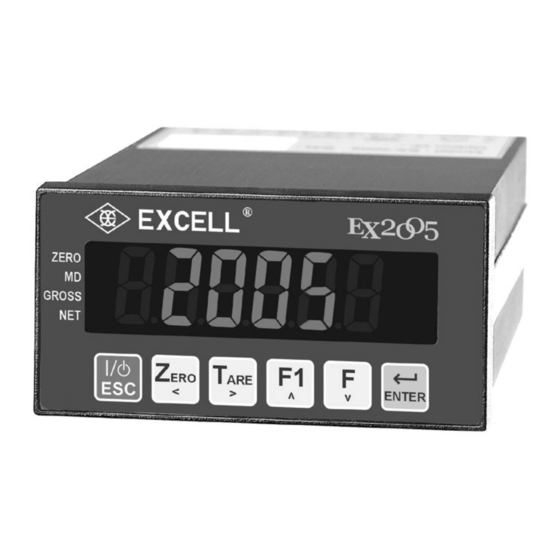
EX2005
© Excell Precision Limited 2015. All rights reserved Worldwide.
The information contained herein is the property of Excell Precision Limited and is supplied
without liability for errors or omissions. No part may be reproduced or used except as
authorised by contract or other written permission.
The copyright and the foregoing
restriction on reproduction and use extend to all media in which the information may be
embodied.
Advertisement
Table of Contents

Related Manuals for Excell EX2005


Summary of Contents for Excell EX2005
- Page 1 EX2005 © Excell Precision Limited 2015. All rights reserved Worldwide. The information contained herein is the property of Excell Precision Limited and is supplied without liability for errors or omissions. No part may be reproduced or used except as authorised by contract or other written permission.
-
Page 3: Table Of Contents
EXCELL PRECISION CO., LTD CONTENT Safety...........................3 Features..........................3 Chapter 1 Front and Rear Panel Specifications................4 1-1 Front panel ......................4 1-2 Rear panel ......................4 1-3 Keypad Description ....................5 1-4 A/D Conversion.......................5 1-5 Power supply ......................5 1-6 Dimensions......................6 Chapter 2 General Function Guide ..................7 2-1 Function Setup and Operation Procedures ............7... - Page 4 EXCELL PRECISION CO., LTD Chapter 5 Interface ......................38 5-1 Serial Input / Output Interface (default OP-01) .............38 5-2 BCD parallel output interface (OP-02) ........46 5-3 Analogue Current / Voltage Output Interface (OP-03) ..........48 5-4 External Parallel Input / Output Interface..............50 Chapter 6 Maintenance......................55...
-
Page 5: Safety
C ~ 40 C (32 °F ~ 104 °F). Features EX2005 has a wide range of applications from batching to simple weighing. Features: Stand alone batching mode or connect to PLC for external system control Built in batching / dosing functions... -
Page 6: Chapter 1 Front And Rear Panel Specifications
EXCELL PRECISION CO., LTD Chapter 1 Front and Rear Panel Specifications 1-1 Front panel Weight Unit Indication Display Area Display • 6 digits, bright red, 7 segment LED display, character height 16mm (0.63”). • Display can be switched between Gross Weight / Net Weight / Totalised Weight / Number of transactions in the total. -
Page 7: Keypad Description
EXCELL PRECISION CO., LTD 1-3 Keypad Description When entering data or reference setting, it means “ESC”. In the normal operation, it puts the indicator in standby mode or escape. Entering standby mode: All of the display (except ZERO “3” symbol) and serial data output are disabled. -
Page 8: Dimensions
EXCELL PRECISION CO., LTD 1-6 Dimensions 04011210 ZSME400000003... -
Page 9: Chapter 2 General Function Guide
EXCELL PRECISION CO., LTD Chapter 2 General Function Guide 2-1 Function Setup and Operation Procedures Function Operation Display Description Enter calibration mode Turn the calibration switch to “ON” See 3-2 for details Press not release, See 2-2 for details then press... -
Page 10: Error Messages (Display In General Function Setting)
EXCELL PRECISION CO., LTD Function Operation Display Description Press the key to set Check weighing setpoint See 4-2 for details the parameter of FUNC.4 to 1 in parameter setting the normal mode Key actions in function set up mode ⇒ Increases the number of the flashing digit ⇒... - Page 11 EXCELL PRECISION CO., LTD Function Setting Procedures With weight displayed press and hold the key. Then, press See Function Setting 2-2 for details Function Setting See 5-1 for details First Serial Port Interface See 5-1 for details Second Serial Port...
-
Page 12: Function Setting
EXCELL PRECISION CO., LTD 2-3 Function Setting *Function Parameter code Press ⇒ Digital Filter I ⇒ Digital Filter II ⇒ Lock keypad function Input desired ⇒ Parameter code “F” function setting ⇒ “F1” function setting ⇒ Front panel indication “◄” setting (first) Press ⇒... - Page 13 EXCELL PRECISION CO., LTD FNC Group function setting Setting value Item Function Default Parameter Description 5 Hz 4.17 Hz 2.5 Hz 2.08 Hz 1.25 Hz FNC-01 Digital Filter I 1.04 Hz 0.63 Hz 0.52 Hz 0.31 Hz 0.26 Hz Disabled...
- Page 14 EXCELL PRECISION CO., LTD Setting value Item Function Default Parameter Description Parameter ⇒ Description ⇒ Zero Front panel indication “◄” FNC-06 ⇒ MD setting (top) ⇒ Gross ⇒ Net ⇒ Totalised weight (Accu. V) Front panel indication “◄” ⇒ Totalised transactions (Accu. C)
-
Page 15: Chapter 3 Calibration
EXCELL PRECISION CO., LTD Setting value Item Function Default Parameter Description Disable FNC-13 Turn-on zero setting Enable Disable all the functions under stand-by mode FNC-14 Stand-by mode setting Only turn off display but not disable other functions under stand-by mode... -
Page 16: Parameter Setting And Calibration Flow Chart
EXCELL PRECISION CO., LTD 3-2 Parameter Setting and Calibration Flow Chart Calibration Switch ON Linearity General Digital MODBUS Specification Calibration Calibration Calibration Calibration Calibration Zero point Select 1 Point for Zero Point Voltage Calibration Weight Calibration Calibration (1P~5P) Weight Calibration... -
Page 17: Calibration Process
EXCELL PRECISION CO., LTD Calibration process Calibration Switch set to ON Entering the General calibration, see 3.3 for details MODBUS Calibration Entering the specification calibration, see 3.4 for details Spec. Calibration Entering the General calibration, see 3.5 for General Calibration... -
Page 18: Modbus Calibration
EXCELL PRECISION CO., LTD 3-3 MODBUS Calibration RS1-02 set as “4” (MODBUS RTU mode) RS1-07 set as “01” (address) Press Keep flashing Zero calibration Input 01050423FF007CC0 ← zero calibration Reading calibration status Input 0101004100565AC1D ← Refer to “Appendix 3: MODBUS data address table”... -
Page 19: Specification Calibration
EXCELL PRECISION CO., LTD 3-4 Specification calibration *Calibration parameter code ⇒Unit Press ⇒Decimal Point ⇒Min. Division Key in calibration ⇒Max. Capacity code ⇒Zero Range ⇒Time of Zero tracking ⇒Range of Zero tracking Press ⇒Investigate period of unstable ⇒Investigate range of unstable Display shows the ⇒Function Zero and Tare when the... - Page 20 EXCELL PRECISION CO., LTD Setting value Item Function Default Parameter Description None CSP-01 Unit None 1 Decimal Point Decimal CSP-02 Point 2 Decimal Point 3 Decimal Point CSP-03 Division Division size 999999 Max. ↓ CSP-04 Max. capacity 999999 Capacity 000000 Zero range = calibration zero point ±...
-
Page 21: General Calibration
EXCELL PRECISION CO., LTD 3-5 General Calibration Set CAL switch to ON Select General Calibration Press Zero Calibration No weight on the platform or in the hopper Press the ..Five sec. later Two sec. later... -
Page 22: Linearity Calibration
EXCELL PRECISION CO., LTD 3-6 Linearity calibration Before the Linearity calibration, the General calibration should be completed. Set CAL switch to ON Select linearity calibration to select one of calibration points (1P~5P) Press the : no setting value : with setting value... - Page 23 EXCELL PRECISION CO., LTD Display the setting value of linearity calibration Set CAL switch to ON Select linearity calibration to select one of calibration points (1P~5P) : no setting value Press the : with setting value Press the Display the setting value of...
-
Page 24: Digital Calibration
EXCELL PRECISION CO., LTD 3-7 Digital calibration Set CAL switch to ON Example: mV/V Select Digital calibration Span voltage (SPAN) Press the Zero voltage (ZERO) Capacity ( CAP. ) Weight Two sec. later Zero Voltage ⇒ 0.00036 mV/V(incl. dead load) Span Voltage ⇒... -
Page 25: Chapter 4 Weight Comparison Procedures
EXCELL PRECISION CO., LTD Chapter 4 Weight Comparison Procedures 4-1 Function Configuration Menu *Item code ⇒ Batching mode ⇒ Batching start delay time ⇒ Compare SP1 & SP” waiting time Press the ⇒ Batch finishes output signal delay time ⇒ Batch finish condition ⇒... - Page 26 EXCELL PRECISION CO., LTD Functional Parameter Instruction Setting value Item Function Default Parameter Description Normal batch Loss-in weight Comparison mode SQ- 01 Batching mode Normal batch (Built-in program) Loss-in weight (Built-in program) Hold mode (Built-in program) The built-in auto-program starts the 0.0 ~ 25.5...
- Page 27 EXCELL PRECISION CO., LTD Setting value Item Function Default Parameter Description Discharge start delay 0.0 ~ 25.5 SQ- 10 Delay time before Discharge signal is ON time (sec) Discharge stop delay 0.0 ~ 25.5 SQ- 11 Delay time before Discharge signal is OFF...
-
Page 28: Check Weighing Configuration
EXCELL PRECISION CO., LTD 4-2 Check Weighing Configuration 1. FNC-04 = 1, SQ-01 = 1, 2, 4 or 5 Press the Display shows the existing Display shows the existing Under Final value setting, Input new value setting. Input new value as value as required. - Page 29 EXCELL PRECISION CO., LTD 2. FNC-04 = 1, SQ-01 = 3 Press the Display shows the existing Hi value setting, Input new value as required. Press the Display shows the existing Lo value setting, Input new value as required. Press the Display shows the existing Zero Band setting.
- Page 30 EXCELL PRECISION CO., LTD 3. FNC-04 = 1, SQ-01 = 6 Press the Display shows the existing Hi value setting, Input new value as required. Press the Display shows the existing Lo value setting, Input new value as required. Press the Display shows the existing Zero Band setting, Input new value as required.
-
Page 31: Batching Signal Outputs
EXCELL PRECISION CO., LTD 4-3 Batching Signal Outputs Normal batching signal outputs Signal Output condition Net ≥ Final(value) - SP1(value) Net ≥ Final(value) - SP2(value) Net ≥ Final(value) – Free Fall (in-flight) (value) Net < Final(value) – Under(value) Under Net ≥ Final(value) + Over(value) Over Gross ≤... -
Page 32: Normal Batching Flow Chart (Sq-01=1)
EXCELL PRECISION CO., LTD 4-4 Normal batching flow chart (SQ-01=1) 04011210 ZSME400000003... -
Page 33: Loss-In Weight Flow Chart (Sq1=2)
EXCELL PRECISION CO., LTD 4-5 Loss-in Weight flow chart (SQ1=2) 04011210 ZSME400000003... -
Page 34: Hi, Ok, Lo Output Flowchart
EXCELL PRECISION CO., LTD 4-6 Hi, OK, Lo output flowchart JUDGMENT Setting: IN 01~08=12 or FNC04~05=6 04011210 ZSME400000003... -
Page 35: Normal Batching (Built-In Program) Flowchart (Sq-01=4)
EXCELL PRECISION CO., LTD 4-7 Normal batching (built-in program) flowchart (SQ-01=4) If to activate circulatory ● function, please wait till zero signal output. Batch signal setting 1. FNC04~05=4、5 2. IN01~08=4、5 3. If use "unloading continuously control" (SQ14), please keep batch start signal ON... -
Page 36: Loss-In Weight (Built In Program) (Sq-01=5)
EXCELL PRECISION CO., LTD 4-8 Loss-in Weight (built in program) (SQ-01=5) Batch signal setting 1. FNC04~05=4、5 2. IN01~08=4、5 04011210 ZSME40000003... -
Page 37: Hold Mode (Sq-01 = 6)
EXCELL PRECISION CO., LTD 4-9 Hold mode (SQ-01 = 6) 1. General hold mode (FNC-11 = 0) Hold (Key / Ext.In) Hold Release (Key / Ext.In) 2. Peak hold mode ( FNC-11 = 1、2 ) 3. Peak hold mode ( FNC-11 = 3、4 ) -
Page 38: Hold Mode Flow Chart
EXCELL PRECISION CO., LTD 4-9-1 Hold mode flow chart (SQ-01=6,SQ-16=0 or 2 or 4) HOLD signal setting: 1. FNC04~05=10、11 2. IN01~08=7、8 JUDGMENT Setting: IN 01~08=12 or FNC04~05=6 04011210 ZSME400000003... -
Page 39: Hi, Ok, Lo Comparison
EXCELL PRECISION CO., LTD 4-9-2 Hi, OK, Lo comparison 1. Normal HOLD ( FNC-11 = 0 ) Entering the Hold mode, Hi, OK, Lo comparison output. Escape Hold mode will switch off the outputs. 2. Peak HOLD ( FNC-11 = 1, 2 ) If Peak Ready is ON, Hi, OK, Lo comparison output. -
Page 40: Chapter 5 Interface
EXCELL PRECISION CO., LTD Chapter 5 Interface 5-1 Serial Input / Output Interface (default OP-01) Pin location and setting 1. Default RS232 and Current-loop Function Current loop out Current loop out 2. OP-01 RS-422 / RS-485 / RS-232 RS-232 RS-422/485 Function 1.TxD... - Page 41 EXCELL PRECISION CO., LTD Connection type RS-422 RS- 485 电脑主机 电脑主机 Host computer Host computer SDA (1) SDA(1) SDB(2) SDB (2) RDA(3) RDA (3) RDB(4 ) RDB(4) SG ( 6 ) SG (6) TRM (5) TRM( 5) EX- 2002 EX- 2002...
- Page 42 EXCELL PRECISION CO., LTD Function setting First serial port interface Setting procedure Press the Press the Input desired Input desired Parameter code Parameter code Press the Press the Display shows the existing Display shows the existing parameter code. Input parameter code. Input...
- Page 43 EXCELL PRECISION CO., LTD Setting value Item Function Default Para- Description meter As display Gross only Net only As display (simple) Gross (simple) Net (simple) RS1- 01 Transmit format RS2- 01 Comparison + As display (simple) Comparison +Gross (simple) Comparison +Net (simple) Tare Totalised (Accu.) Weight and number of...
- Page 44 EXCELL PRECISION CO., LTD Data format 1. General Format GROSS S TARE CR LF + OL + SP SP SP SP SP SP SP SP SP - OL SP SP SP SP SP SP SP SP SP UNSTABLE 2. Totalised (Accu.) Format (RS1-01 / RS2-01=10) Accu.
- Page 45 EXCELL PRECISION CO., LTD 5. Comparison condition (2) Byte 0 Byte 1 Byte 2 Byte 3 Byte 4 Byte 5 Byte 6 Byte 7 Byte 0 : Zero Band Byte 1 : Over : 0 ( ASC II Code 30 H )
- Page 46 EXCELL PRECISION CO., LTD Command mode 1. Command Format A Host Command <CR>< LF> Slave Command <CR>< LF> Zero Zero compensation On/OFF Tare Clear TARE value Gross Weight Net weight Accu. Current net weight and times plus 1 Deduct times of last accu. Value minus 1 Clear accu.
- Page 47 EXCELL PRECISION CO., LTD 3. COMMAND FORMAT C Host Command + Data <CR>< LF> Slave Command + Data <CR>< LF> Write weight compared value WS□□XXXXXX XXXXXX : value (6 bytes) □□ : setting items Write SP1 Write target item of unload value...
-
Page 48: Bcd Parallel Output Interface (Op-02)
EXCELL PRECISION CO., LTD 5-2 BCD parallel output interface (OP-02) PIN Location D-Sub 37PIN Function Function 1×10 2×10 4×10 8×10 1×10 2×10 4×10 8×10 1×10 2×10 4×10 8×10 1×10 2×10 4×10 8×10 1×10 2×10 4×10 8×10 1×10 2×10 4×10 8×10... - Page 49 EXCELL PRECISION CO., LTD Function setting Press the Input desired Parameter code Press the Display shows the existing ⇒ Increment flashing digit parameter code. Input new code as need. ⇒ Decrement flashing digit Press the ⇒ Move flashing point left ⇒...
-
Page 50: Analogue Current / Voltage Output Interface (Op-03)
EXCELL PRECISION CO., LTD 5-3 Analogue Current / Voltage Output Interface (OP-03) Location 1. A (+) 2. V (+) 3. Com. (-) 4. FG SPAN ZERO 11 12 13 A. Terminal (4 way) 1 : 0 ~ 20mA current output, positive... - Page 51 EXCELL PRECISION CO., LTD Function setting Press the Input desired Parameter code Press the Display shows the existing ⇒ Increment flashing digit parameter code. Input new code as required. ⇒ Decrement flashing digit Press the ⇒ Move flashing point left ⇒...
-
Page 52: External Parallel Input / Output Interface
EXCELL PRECISION CO., LTD Analogue output notes 1. The current output, load resistor should not exceed 550 Ω. It is recommended that a resistor with a low temperature coefficient and a power rating above 0.2 W be used. 2. Avoid short circuits between the positive and negative analogue output terminals as the interface this may cause damage. - Page 53 EXCELL PRECISION CO., LTD Input signal configuration Press the Input desired Parameter code Press the ⇒ Increment flashing digit ⇒ Decrement flashing digit Display shows the existing parameter code. Input ⇒ Move flashing point left new code as required. Press the ⇒...
-
Page 54: Parameter Description
EXCELL PRECISION CO., LTD Output signal setting Press the Input desired Parameter code ⇒ Increment flashing digit Press the ⇒ Decrement flashing digit ⇒ Move flashing point left Display shows the existing ⇒ Move flashing point right parameter code. Input new code as required. - Page 55 EXCELL PRECISION CO., LTD Equivalent Circuits Input Indicator inside Ic ≅ 5mA IN 1 ~ IN 8 COM 1 IN 1 ~ IN 8 and COM 1. Input signal - Open ↔ OFF, Short ↔ ON. Warning: Don’t use external power (AC or DC) to connect to the input terminals.
- Page 56 EXCELL PRECISION CO., LTD Thumbwheel Switches (for OP-04) The interface can connect to external thumbwheel switches or a PLC to input various parameters depending on the configuration of SQ-01. The input variables are: Final (5 digits), SP2 (4 digits) & Free Fall (3 digits).
-
Page 57: Chapter 6 Maintenance
EXCELL PRECISION CO., LTD Chapter 6 Maintenance 6-1 Restore All Parameters to Their Default Factory Values. (1) While the indicator is counting back to zero, adjust SW to ON and press keys. (2) Display shows the flashing digits (3) Confirm / abort. -
Page 58: Restore The Function Parameter Back To Its Default Value
EXCELL PRECISION CO., LTD 6-2-1 Restore the function parameter back to its default value (1) During the indicator count back to zero, press keys. (2) The display shows (3) Press the key and the display shows flashing. (4) Confirm / abort. -
Page 59: Test Mode
EXCELL PRECISION CO., LTD 6-3 Test mode During the indicator count back to zero Press keys ⇒ 7 segment display testing. See for details 6-3-1. ⇒ Keypad and calibration SW testing. See for details 6-3-2. ⇒ Display A/D internal value display. -
Page 60: 7-Segment Display Testing
EXCELL PRECISION CO., LTD 6-3-1 7-Segment display testing The display will show , then display “ ” and all of the icons. To exit press the 6-3-2 Keypad and calibration SW testing Setting the calibration SW to “ON”, or pressing any key will cause the related display →... - Page 61 EXCELL PRECISION CO., LTD OP-03 Analogue current output interface testing 1) 4 ~ 20 mA current output testing Use an ammeter to measure the output current between pin1 & pin 3 of the interface. Use the keys to select the output current level desired.
-
Page 62: Appendix 1 Description Of 7-Segment Characters
EXCELL PRECISION CO., LTD Appendix 1 Description of 7-Segment Characters Digit 7 segments letter Alphabet 7 segments letter Alphabet 7 segments letter 04011210 ZSME400000003... -
Page 63: Appendix 2 Function Table
EXCELL PRECISION CO., LTD Appendix 2 Function Table Specification Calibration Setting value Item Function Default Parameter Description None CSP-01 Unit None 1 Decimal Point Decimal CSP-02 Point 2 Decimal Point 3 Decimal Point CSP-03 Division Division size 999999 Max. ↓... - Page 64 EXCELL PRECISION CO., LTD FNC Group Function Setting Setting value Item Function Default Parameter Description 5 Hz 4.17 Hz 2.5 Hz 2.08 Hz 1.25 Hz FNC-01 Digital Filter I 1.04 Hz 0.63 Hz 0.52 Hz 0.31 Hz 0.26 Hz Disabled...
- Page 65 EXCELL PRECISION CO., LTD Setting value Item Function Default Parameter Description Parameter ⇒ Description ⇒ Zero Front panel indication “◄” FNC-06 ⇒ MD setting (top) ⇒ Gross ⇒ Net ⇒ Totalised weight (Accu. V) Front panel indication “◄” ⇒ Totalised transactions (Accu. C)
- Page 66 EXCELL PRECISION CO., LTD Setting value Item Function Default Parameter Description Disable FNC-13 Turn-on zero setting Enable Disable all the functions under stand-by mode FNC-14 Stand-by mode setting Only turn off display but not disable other functions under stand-by mode...
- Page 67 EXCELL PRECISION CO., LTD Serial Input/Output Interface (Build in OP-1) Setting value Item Function Default Para- Description meter As display Gross only Net only As display (simple) Gross (simple) Net (simple) RS1- 01 Transmit format RS2- 01 Comparison + As display (simple)
- Page 68 EXCELL PRECISION CO., LTD BCD Parallel Output Interface (OP – 02) Setting value Item Function Default Parameter Description As display bCd- 01 Data type Gross Transmit continuous bCd- 02 Transmit mode Auto transmit Manual transmit Positive logic action bCd- 03...
- Page 69 EXCELL PRECISION CO., LTD External Parallel Input/Output Interface (Op-04 & Op-05) OP-04 Control I/O (4 in / 4 out) + Setpoint Input (BCD code) Signal Signal Code 100 Code 101 Code 102 Code 103 Code 104 Code 105 Code 106...
- Page 70 EXCELL PRECISION CO., LTD Function Configuration Menu Setting value Item Function Default Parameter Description Normal batch Loss-in weight Comparison mode SQ- 01 Batching mode Normal batch (Built-in program) Loss-in weight (Built-in program) Hold mode (Built-in program) The built-in auto-program starts the 0.0 ~ 25.5...
- Page 71 EXCELL PRECISION CO., LTD Setting value Item Function Default Parameter Description Discharge start delay 0.0 ~ 25.5 SQ- 10 Delay time before Discharge signal is ON time (sec) Discharge stop delay 0.0 ~ 25.5 SQ- 11 Delay time before Discharge signal is OFF...
-
Page 72: Appendix 3 Modbus Data Address Table I
EXCELL PRECISION CO., LTD Appendix 3 MODBUS Data Address Table I Data Register Bit I/O Bit I/O Function Code 01 (Read) Function Code 05 and 15 (Write) Function Code 03 (Read Modbus SCALE Modbus SCALE Output Modbus SCALE Input 40000 ~ 40001... -
Page 73: Appendix 4 Modbus Data Address Table Ii
EXCELL PRECISION CO., LTD Appendix 4 MODBUS Data Address Table II (For Hitech and Pro-face Human Machine Interface) Data Register Bit I/O Bit I/O Function Code 03 (Read) Function Code 01 (Read) Function Code 05 and 15 (Write) Modbus SCALE... -
Page 74: Appendix 5 Examples For Input And Output Of Modbus
EXCELL PRECISION CO., LTD Appendix 5 Examples for Input and Output of Modbus Examples here use Appendix 3 and can also be applied to appendix 4, with different Modbus Data Address. CRC : Error check code Function code 03: Modbus (40000~40001) Weight Display... - Page 75 EXCELL PRECISION CO., LTD Function code 06: Modbus (41026): write batch finish delay time write Name Input Description Name Output Description ID Address Machine ID ID Address Machine ID Function Function code code Batch Finish delay Batch Finish delay Register's...