Advertisement
Quick Links
Advertisement

Related Manuals for Delta Electronics DVP-SS2


Summary of Contents for Delta Electronics DVP-SS2
- Page 1 2010-06-15 5011699700-S2S0 DVP-1160070-01...
-
Page 2: Product Profile
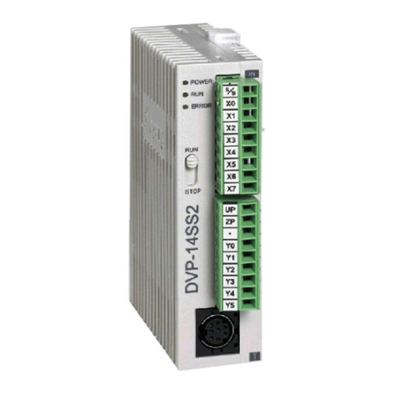
………………………………………………………………… …………………………………………………………………… Thank you for choosing Delta DVP-SS2. DVP-SS2 is a 14-point (8DI + 6DO) PLC MPU, offering various instructions and with 8k steps program memory, able to connect to all DVP-S series extension models, including digital I/O (max. 480 I/O points) and analog modules (for A/D, D/A conversion and temperature measurement). - Page 3 Model DVP14SS211R DVP14SS211T Item Fuse capacity 1.85A/30VDC, Polyswitch Power consumption 1.8W 1.5W Power protection With counter-connection protection on the polarity of DC input power Insulation resistance > 5MΩ (all I/O point-to-ground: 500VDC) ESD: 8kV Air Discharge Noise immunity EFT: Power Line: 2kV, Digital I/O: 1kV, Analog & Comm. I/O: 250kKV RS: 26MHz ~ 1GHz, 10V/m The diameter of grounding wire cannot be smaller than the wire Grounding...
-
Page 4: Power Supply
Relay (Sink Or Source) 14SS211T Transistor Note: The layout of output terminals on DVP-SS2 is different from that on DVP-SS. Dimension & Installation Please install the PLC in an enclosure with sufficient space around it to allow heat dissipation, See [Figure 3]. -
Page 5: Safety Wiring
[ Figure 5 ] Output Point Wiring 1. DVP-SS2 has two output modules on it, relay and transistor. Be aware of the connection of shared terminals when wiring output terminals. 2. Output terminals, Y0, Y1, and Y2, of relay models use C0 common port; Y3, Y4, and Y5 use C1 common port. - Page 6 3. Output terminals, Y0 ~Y5 of transistor models use UP, ZP common port. See [Figure 4. Isolation circuit: The optical coupler is used to isolate signals between the circuit inside PLC and input modules. Relay (R) output circuit wiring DC power supply Emergency stop: Uses external switch Fuse: Uses 5~10A fuse at the shared terminal of output contacts to protect the output circuit Transient voltage suppressor (SB360 3A 60V): Extends the life span of contact.
- Page 7 DC power supply Emergency stop Circuit protection fuse The output of the transistor model is “open collector”. If Y0/Y1 is set to pulse output, the output current has to be bigger than 0.1A to ensure normal operation of the model. 1.