Table of Contents
Advertisement
Quick Links
Bernard BTB MIG Guns
OWNER'S MANUAL
Bernard
A Division of Miller Electric Mfg. Co.
449 West Corning Road
Beecher, Illinois 60401 USA
OM-BTB-1.7
Processes
MIG (GMAW) Welding
Description
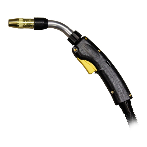
Semi-Automatic, Air-Cooled, MIG
(GMAW) Welding Gun
Phone: 1-855-MIGWELD (644-9353)
1-519-737-3000
(International)
Fax: 708-946-6726
For more information, visit us at BernardWelds.com
May 2017
(US & Canada)
Advertisement
Table of Contents

Related Manuals for Bernard Q20 Series


Summary of Contents for Bernard Q20 Series
- Page 1 OM-BTB-1.7 May 2017 Processes MIG (GMAW) Welding Description Semi-Automatic, Air-Cooled, MIG (GMAW) Welding Gun Bernard BTB MIG Guns OWNER’S MANUAL Bernard Phone: 1-855-MIGWELD (644-9353) (US & Canada) A Division of Miller Electric Mfg. Co. 1-519-737-3000 (International) 449 West Corning Road...
- Page 2 Thank You for Choosing Bernard Thank you for selecting a Bernard product. The MIG gun you have purchased has been carefully assembled and is ready to weld and factory tested prior to shipment to ensure high performance. Before installing, compare the equipment received against the invoice to verify that the shipment is complete and undamaged.
-
Page 3: Table Of Contents
2-2 Duty Cycle and Overheating............................SECTION 3 - INSTALLATION......................3-1 Installing to a Feeder with a Power Pin........................3-2 Installing to a Feeder with a Euro or Bernard Power Pin..................SECTION 4 - OPERATION....................... 4-1 Pulling the Trigger................................. SECTION 5 - REPLACEMENT...................... -
Page 4: Declaration Of Conformity
DECLARATION OF CONFORMITY for European Community (CE marked) products. Bernard Welding, 449 West Corning Rd., Beecher, IL 60401 U.S.A. declares that the product(s) identified in this declaration conform to the essential requirements and provisions of the stated Council Directive(s) and Standard(s). -
Page 5: Section 1 - Safety Precautions For Gmaw Welding Guns - Read Before Using
SECTION 1 - SAFETY PRECAUTIONS - READ BEFORE USING 1-1 Fume and Gas Hazards WELDING AND CUTTING can cause fire or explosion FUMES AND GASES can be hazardous Welding or cutting on closed containers, such Welding and cutting produces fumes and as tanks, drums or pipes can cause them to gases. - Page 6 ELECTRIC SHOCK can kill • If earth grounding of the workpiece is required, ground it directly with a separate cable. Touching live electrical parts can cause fatal • Do not touch electrode if you are in contact with the work, shock or severe burns.
-
Page 7: Additional Safety Warnings For Installation, Operation And Maintenance
1-3 Additional Safety Warnings for MOVING PARTS can injure Installation, Operation and Maintenance • Keep away from moving parts such as fans. HOT PARTS can burn • Keep all doors, panels, covers and guards closed and securely in place. • Do not touch hot parts bare handed. •... - Page 8 • Be sure welding machine or plasma cutter is installed COMPRESSED AIR can injure or kill and grounded according to its Owner’s Manual. • If interference still occurs, the user must take extra • Before working on compressed air system, measures such as moving the welding or cutting turn off and lockout/tagout unit, release machine, using shielded cables, using line filters, or...
-
Page 9: California Proposition 65 Warning
1-7 Commercial Warranty fitness for any purpose. Bernard shall not be liable under any circumstances to Buyer, or Product is warranted to be free from defects in material and to any person who shall purchase from Buyer, for damages of any workmanship for 1 Year after the sale by an authorized Buyer. -
Page 10: Section 2 - Specifications
SECTION 2 - SPECIFICATIONS 2-1 Specifications Air-Cooled MIG Guns for GMAW Welding 200 amp gun feeds maximum wire size of 1/16” (1.6 mm) Duty Cycle Rating: 100%: 200 Amp with Shielding gas 60%: 200 Amp with Mixed Gases 300 amp gun feeds maximum wire size of 5/64” (2.0 mm) Duty Cycle Rating: 100%: 300 Amp with Shielding Gas... -
Page 11: Section 3 - Installation
2. Insert control plug into feeder. 3. Feed welding wire into power pin by hand and tighten drive rolls. 3-2 Installing to a Feeder with a Euro or Bernard Power Pin 1. Insert the Euro power pin to face of receptacle. Thread Euro hand Euro Power Pin nut clockwise to tighten. -
Page 12: Section 4 - Operation
SECTION 4 - OPERATION 4-1 Pulling the Trigger 1. Trigger - When pressed, energized wire feeds and shielding gas flows. Page 9... -
Page 13: Section 5 - Replacement
SECTION 5 - REPLACEMENT 5-1 Changing Consumables 3. Gas diffuser may be removed with an appropriate A. Changing Quik Tip Consumables ™ wrench in a counterclockwise rotation. To install firmly secure gas diffuser with an appropriate wrench 1. Remove threaded nozzle by turning in a counterclockwise in a counter clockwise rotation, torque to 144 in.-lbs. -
Page 14: Changing The Liner
5-2 Changing the Liner A. Changing Universal Conventional Liner 1. Remove nozzle, contact tip, and gas diffuser/ retaining head and lay cable straight. Using a 10 mm wrench, turn liner lock counterclockwise until it is free from the power pin. Remove liner from gun assembly. - Page 15 B. Changing QUICK LOAD Liner ™ 1. Remove the nozzle, contact tip and gas diffuser and lay cable straight. Pull the QUICK LOAD Liner from the end of the neck using pliers. 2. Remove the protective cap from the new QUICK LOAD Liner and insert it through the neck using the wire as a guide.
-
Page 16: Changing The Neck
5-3 Changing the Neck A. Changing the Neck - Rotatable 1. To remove neck, grasp lock nut and rotate counterclockwise. Rotation will free neck from end fitting. To install the neck, perform the above instructions in reverse order and torque to 38 in.-lbs. 2. -
Page 17: Changing The Handle And Switch
E. Changing the Neck - Fixed with C Series Large Straight Handle 1. Place neck in vise. Remove both switch housing mounting screws with a Phillips screwdriver. 2. Remove both the top and bottom pods from handle. 3. Slide handle back, exposing the cable connection. Loosen the cable/neck connection using a 7/8”... - Page 18 C. T Series Small Straight Handle Locking Collar 1. Loosen and remove locking collar. 2. Twist handle lock nut counterclockwise. Slide handle lock nut away from handle. 3. Remove screw from handle and separate handle halves. 4. Remove switch from switch lead connectors with needle nose pliers.
-
Page 19: Changing The Power Pin
5-5 Changing the Power Pin A. Universal Power Pin 1. Remove the liner by following the steps listed in the ‘Changing the Liner’ section. 2. Use wrenches and rotate power pin in a counterclockwise direction to remove it from the adaptor block. 3. - Page 20 Large Contact Snap Ring Small Snap Ring C. Bernard Quick Disconnect Gas Pin 1. Remove liner from gun assembly. Viewing quick disconnect Wave from cable end, align wave spring and large snap ring with Spring opening access slot. Compress large snap ring with internal snap ring pliers and remove locking sleeve.
-
Page 21: Section 6 - Parts List
Straight Rear Strain Relief Clamshell Rear Strain Relief (Euro Power 2520069 Pin) Clamshell Rear Strain Relief with Installed 2520073 Gas Pin (Bernard Power Pin) 414-400 Adapter Block See SP-BTB Spec Sheet* Power Pin See SP-BTB Spec Sheet* Power Pin Insulator... - Page 22 2520041 Spring, Strain Relief 2520023 2520056 2520056 Straight Rear Strain Relief Clamshell Rear Strain Relief with Installed 2520073 Gas Pin (Bernard Power Pin) Clamshell Rear Strain Relief (Euro Power 2520069 Pin) 414-400 Adapter Block See SP-BTB Spec Sheet* Power Pin...
- Page 23 Switch Connector (4 Req’d) 2520041 Spring, Strain Relief 2520056 Straight Rear Strain Relief Clamshell Rear Strain Relief with Installed 2520073 Gas Pin (Bernard Power Pin) Clamshell Rear Strain Relief (Euro Power 2520069 Pin) 414-400 Adapter Block See SP-BTB Spec Sheet*...
- Page 24 320-6 Handle Collar M169700-12 Spring, Handle 320-3 Handle Cap, Locking, Rear Clamshell Rear Strain Relief with Installed 2520073 Gas Pin (Bernard Power Pin) Clamshell Rear Strain Relief (Euro Power 2520069 Pin) 2520033 Spring Strain Relief 216-1 Control Plug Block See SP-BTB Spec Sheet*...
- Page 25 Cable Repair Kit (Includes: (2) #8, (1) 513-8 #9, (1) #10, (1) #11, (1) Conduit Clamp) Handle Straight Rear Strain Relief Clamshell Rear Strain Relief with 2520073 Installed Gas Pin (Bernard Power Pin) Clamshell Rear Strain Relief (Euro Power 2520069 Pin) 411-1 Switch 411-2...
- Page 26 (1) #9, (1) #10, (1) #11, (1) Conduit Clamp) 1780086 Front Handle 1780086 Rear Strain Relief Clamshell Rear Strain Relief with 2520073 Installed Gas Pin (Bernard Power Pin) Clamshell Rear Strain Relief (Euro 2520069 Power Pin) 411-1 Switch 2520058 Trigger Housing, Standard...
-
Page 27: Section 7 - Consumable Parts
SECTION 7 - CONSUMABLE PARTS 7-1 Centerfire Consumable Series ™ Small Centerfire Gas Diffusers and Nozzles NS-5800C (5/8" I.D., Flush, Copper) NS-5818C (5/8" I.D., 1/8" Rec., Copper) NS-5800B (5/8" I.D., Flush, Brass) NS-5818B (5/8" I.D., 1/8" Rec., Brass) 'T' Series Tip NS-1218C (1/2"... -
Page 28: Quik Tip™ Consumable Series
7-2 Quik Tip Consumable Series ™ Quik Tip Gas Diffusers and Nozzles N1C34HQ Plated Copper, 3/4 " Heavy Duty N1C58HQ Plated Copper, 5/8 " Heavy Duty N1C34Q Plated Copper, 3/4 " Heavy Duty N1B34Q Brass, 3/4 " D114Q N1C58Q Plated Copper, 5/8 "... -
Page 29: Centerfire Hd Consumable Series
7-3 Centerfire HD Consumable Series ™ Centerfire HD Consumable Series is not configurable and will need to be ordered separately. Couple the Centerfire HD nozzle body with a Centerfire HD nozzle cone to form a complete Centerfire HD nozzle. 3414 (3/4"... -
Page 30: Tough Lock™ Consumable Series
7-5 TOUGH LOCK Consumable Series ™ TOUGH LOCK™ CONTACT TIP PART NUMBERS WIRE SIZE STANDARD DUTY HEAVY DUTY HEAVY DUTY TAPERED EXTENDED LIFE HEAVY DUTY EXTRA HEAVY DUTY 0.023" (0.6 mm) 403-14-23 0.030" (0.8 mm) 403-14-30 403-20-30 403-21-30 403-27-30 0.035" (0.9 mm) 403-14-35 403-20-35 403-21-35 403-27-35... -
Page 31: Section 8 - Troubleshooting
1. Replace with proper size. 2. Electrode eroding contact tip. 2. Inspect and/or change drive rolls. 3. Exceeding duty cycle. 3. Replace with properly rated Bernard MIG Gun. 5. Erratic arc 1. Worn contact tip. 1. Replace. 2. Buildup inside of liner. - Page 32 11. Tighten gun & cable connections to specified torque. See ‘Replacement’ (Section 5). 9. Gun running hot 1. Exceeding duty cycle. 1. a. Replace with properly rated Bernard MIG Gun. b. Decrease parameters to within gun rating. 2. Loose or poor power connection.
- Page 33 NOTES Page 30...
- Page 34 , Clean Air ™ , Centerfire ™ , Quik Tip ™ and other names are trademarks of Bernard, a division of Miller Electric Mfg. Co. TOUGH LOCK and QUICK LOAD are trademarks of Tregaskiss, a division of ITW Canada Inc. ™ ™...