Table of Contents
Advertisement
Quick Links
Advertisement
Table of Contents

Related Manuals for Bernard T-Gun 500 amp


Summary of Contents for Bernard T-Gun 500 amp
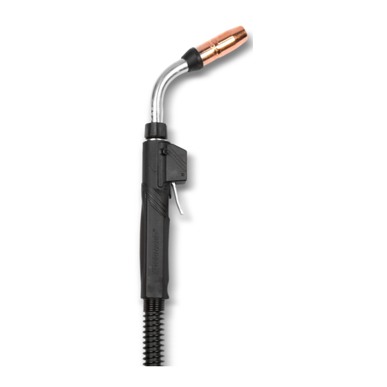
- Page 1 ® Bernard T-Gun™ 450, 600 amp Semi-Automatic Water-Cooled MIG Gun OWNER'S MANUAL TG008-1.0 May 2021 Semi-Automatic, Water-Cooled, MIG (GMAW) Welding Gun Tregaskiss.com/TechnicalSupport 1-855-MIGWELD (644-9353) (US & Canada) +1-519-737-3000 (International)
- Page 2 Thank You for Choosing Bernard Thank you for selecting a Bernard product. Before installing, compare the equipment received against the invoice to verify that the shipment is complete and undamaged. It is the responsibility of the purchaser to file all claims of damage or loss that may have occurred during transit with the carrier. The owner’s manual contains general information, instructions and maintenance to help better maintain your MIG gun or peripheral. Please read, understand and follow all safety precautions. While every precaution has been taken to assure the accuracy of this owner’s manual, Bernard assumes no responsibility for errors or omissions. Bernard assumes no liability for damages resulting from the use of information contained herein. The information presented in this owner’s manual is accurate to the best of our knowledge at the time of printing. Please reference Tregaskiss.com for updated material. For customer support and special applications, please call the Bernard Customer Service Department at 1-855-MIGWELD (644-9353) (US & Canada) or +1-519-737-3000 (International), fax 1-708-946-6726, or email at cs@itwmig.com. Our trained Customer Service Team is available between 8:00 a.m. and 5:30 p.m. EST, and will answer your product application or repair questions. Bernard manufactures premium semi-automatic (GMAW) and FCAW (flux-cored) welding guns, consumables, accessories and manual arc products. For more information on other premium Bernard products, contact your local Bernard distributor or visit us on the web at Tregaskiss.com. Subject to Change – The information presented in this manual is accurate to the best of our knowledge at the time of printing.
-
Page 3: Table Of Contents
TABLE OF CONTENTS SECTION 1 — SAFETY PRECAUTIONS — READ BEFORE USING 1-1 Symbol Usage 1-2 Arc Welding Hazards 1-3 California Proposition 65 Warnings 1-4 Principal Safety Standards 1-5 EMF Information 1-6 Commercial Warranty SECTION 2 — CONSIGNES DE SÉCURITÉ — LIRE AVANT UTILISATION 2-1 Symboles utilisés 2-2 Dangers relatifs au soudage à l'arc 2-3 Proposition californienne 65 Avertissements 2-4 Principales normes de sécurité 2-5 Informations relatives aux CEM SECTION 3 — PRECAUCIONES DE SEGURIDAD — LEA ANTES DE USAR 3-1 Uso de símbolos 3-2 Peligros en soldadura de arco 3-3 Advertencias de la Proposición 65 del estado de California... - Page 4 SECTION 8 — PARTS LIST 8-1 450 amp Model 8-2 600 amp Model SECTION 9 — TROUBLESHOOTING 9-1 Troubleshooting Table ADDITIONAL SUPPORT MATERIALS TG008-1.0...
-
Page 5: Section 1 - Safety Precautions - Read Before Using
SECTION 1 — SAFETY PRECAUTIONS — READ BEFORE USING Protect yourself and others from injury – read, follow, and save these important safety precautions and ELECTRIC SHOCK can kill. operating instructions. Always wear dry insulating gloves. ... - Page 6 ARC RAYS can burn eyes and skin. WELDING WIRE can injure. Arc rays from the welding process produce intense Keep hands and body away from gun tip when visible and invisible (ultraviolet and infrared) rays trigger is pressed. that can burn eyes and skin. Sparks fly off from the weld. READ INSTRUCTIONS. Wear an approved welding helmet fitted with a proper shade of filter lenses to protect your face and eyes from arc rays and Read and follow all labels and the Owner's sparks when welding or watching (see ANSI Z49.1 and Z87.1 Manual carefully before installing, operating, listed in Principal Safety Standards). or servicing unit. Read the safety information Wear approved safety glasses with side shields under your at the beginning of the Manual and in each section. helmet. Use only genuine replacement parts from the manufacturer. Use protective screens or barriers to protect others from Perform installation, maintenance, and service according to flash, glare and sparks; warn others not to watch the arc. the Owner's Manuals, industry standards, and national, state, ...
-
Page 7: California Proposition 65 Warnings
1-3 California Proposition 65 Warnings WARNING: This product can expose you to chemicals For more information, go to www.P65Warnings.ca.gov. including lead, which are known to the state of California to cause cancer and birth defects or other reproductive harm. 1-4 Principal Safety Standards Safety in Welding, Cutting, and Allied Processes, American Welding Safe Handling of Compressed Gases in Cylinders, CGA Pamphlet P- Society standard ANSI Standard Z49.1. Website: www.aws.org. 1 from Compressed Gas Association. Website: www.cganet.com. Safe Practice For Occupational And Educational Eye And Face Safety in Welding, Cutting, and Allied Processes, CSA Standard Protection, ANSI Standard Z87.1, from American National ... -
Page 8: Commercial Warranty
1-6 Commercial Warranty Product is warranted to be free from defects in material and Bernard and Tregaskiss reserve the right to repair, replace, or workmanship for the period specified below after the sale by an refund the purchase price of non-conforming product. Product authorized Buyer. found not defective will be returned to the Buyer after notification by the Bernard and Tregaskiss Customer Service department. Any ® Bernard BTB Semi-Automatic Air-Cooled MIG Guns: 1 year; TOUGH GUN Reamer component part replaced or repaired pursuant Lifetime warranty on straight handles, straight handle to the Warranty herein shall be further warranted for a period of six months after delivery of the replacement. switches, and rear strain relief ® Bernard W-Gun™ and T-Gun™ Semi-Automatic Water- Bernard and Tregaskiss make no other warranty of any kind, Cooled MIG Guns: 180 days expressed or implied, including, but not limited to the warranties of ® ®... -
Page 9: Section 2 - Consignes De Sécurité - Lire Avant Utilisation
SECTION 2 — CONSIGNES DE SÉCURITÉ — LIRE AVANT UTILISATION Pour écarter les risques de blessure pour vous-même et pour autrui — lire, appliquer et ranger en lieu sûr UN CHOC ÉLECTRIQUE peut tuer. ces consignes relatives aux précautions de sécurité et au mode opératoire. - Page 10 L'ACCUMULATION DE VAPEURS peut causer LES FILS DE SOUDAGE peuvent provoquer des lésions ou la mort. des blessures. Éloigner les mains et le corps de la buse du Quand on n’utilise pas le gaz comprimé de pistolet après avoir appuyé sur la gâchette. protection, fermer le robinet de la bouteille. Assurer toujours la ventilation des zones fermées ou utiliser un appareil respiratoire avec alimentation en air. LIRE LES INSTRUCTIONS.
-
Page 11: Proposition Californienne 65 Avertissements
2-3 Proposition californienne 65 Avertissements AVERTISSEMENT – Ce produit peut vous exposer à des Pour plus d’informations, consulter www.P65Warnings.ca.gov. produits chimiques tels que le plomb, reconnus par l’État de Californie comme cancérigènes et sources de malformations ou d’autres troubles de la reproduction 2-4 Principales normes de sécurité Safety in Welding, Cutting, and Allied Processes, American Welding Safe Handling of Compressed Gases in Cylinders, CGA Pamphlet P- Society standard ANSI Standard Z49.1. Website: www.aws.org. 1 from Compressed Gas Association. Website: www.cganet.com. Safe Practice For Occupational And Educational Eye And Face Safety in Welding, Cutting, and Allied Processes, CSA Standard ... -
Page 12: Section 3 - Precauciones De Seguridad - Lea Antes De Usar
SECTION 3 — PRECAUCIONES DE SEGURIDAD — LEA ANTES DE USAR Protéjase usted mismo y a otros contra lesiones — lea, cumpla y conserve estas importantes UNA DESCARGA ELÉCTRICA puede matarlo. precauciones de seguridad e instrucciones de utilización. Siempre use guantes aislantes secos. ... - Page 13 EL AMONTONAMIENTO DE GAS puede El ALAMBRE de SOLDAR puede causarle enfermarle o matarle. heridas. Mantenga las manos y el cuerpo lejos del tubo Cierre el suministro de gas comprimido de contacto de la antorcha cuando se haya cuando no lo use. presionado el gatillo. Siempre dé ventilación a espacios cerrados o use un respirador aprobado que reemplaza el aire. LEER INSTRUCCIONES.
-
Page 14: Advertencias De La Proposición 65 Del Estado De California
3-3 Advertencias de la Proposición 65 del estado de California ADVERTENCIA: Este producto puede exponerlo a químicos, Para obtener más información, acceda a incluso plomo, que el estado de California conoce como www.P65Warnings.ca.gov. causantes de cáncer, defectos de nacimiento u otros daños reproductivos. 3-4 Estándares principales de seguridad Safety in Welding, Cutting, and Allied Processes, American Welding Safe Handling of Compressed Gases in Cylinders, CGA Pamphlet P- Society standard ANSI Standard Z49.1. Website: www.aws.org. 1 from Compressed Gas Association. Website: www.cganet.com. Safe Practice For Occupational And Educational Eye And Face Safety in Welding, Cutting, and Allied Processes, CSA Standard ... -
Page 15: Section 4 - Specifications
SECTION 4 — SPECIFICATIONS 4-1 Specifications T-Gun 450, 600 amp Semi-Automatic Water-Cooled MIG (GMAW) Welding Guns 450 amp gun Duty Cycle Rating: 100%: 450 amp with CO Shielding Gas 60%: 450 amp with Mixed Gases 600 amp gun Duty Cycle Rating: 100%: 600 amp with CO Shielding Gas 60%: 600 amp with Mixed Gases TG008-1.0... -
Page 16: Section 5 - Installation
SECTION 5 — INSTALLATION 5-1 Installing Quick-Connect Block to Feeder 1. Insert the correct feeder adaptor liner for desired wire diameter Figure 5-A (2 provided) flush with the threaded end of the feeder adaptor. 2. Tighten set screw. 3. Thread feeder adaptor into quick-connect block and tighten. 4. Position assembly into feeder adaptor and trim liner within 1/16" (1.6 mm) of the drive rolls and remove burrs if necessary. 5. Secure assembly into feeder. 6. Thread gas hose nipple into feeder gas fitting. 7. Connect power cable to 1/2" (13 mm) power bolt with appropriate lug. Figure 5-B 8. Tighten all connections. 9. Feed welding wire through assembly by hand and tighten drive rolls. TG008-1.0... -
Page 17: Installing Gun To Quick-Connect Block
5-2 Installing Gun to Quick-Connect Block 1. Guide welding wire into power pin. Figure 5-C 2. Insert power pin to shoulder. 3. Tighten thumb screw securely. 4. Connect control plug lead to control housing on gun. 5. Insert control plug into feeder. 6. Securely clamp blue hose on rear housing to water-out on water cooler and red hose on rear housing to water-in on water cooler. 7. Recheck: a. proper gas flow; b. drive roll pressure; c. voltage and wire feed speed; Figure 5-D d. water flow (minimum 1/2 gallon per minute) at 55-65 psi. WARNING: Ensure water supply is on before operation. Figure 5-E TG008-1.0... -
Page 18: Installing Power Pin To Gun
5-3 Installing Power Pin to Gun IMPORTANT: The thread-in two-piece power pin incorporates a Figure 5-F taper to seat and lock the power pin to the rear handle block. Make sure power pin is tightened in the block with a wrench to ensure pin is secure and will not come loose. NOTE: The rear handle and screws do not have to be removed when installing the two-piece power pins. 1. Thread power pin into the rear handle block. 2. Tighten the power pin into the rear block using a 1-1/4" wrench on the rear block and a 5/8" wrench on the power pin. 3. Install liner. See section 6-4 Changing the Liner on page 18. 4. Install gun to feeder as per the instructions in immediately below. 5. For most power pins: a. Insert power pin to shoulder and secure. b. Insert control plug to control housing of gun. c. Insert control plug into feeder. d. Feed welding wire into power pin by hand and tighten drive rolls. e. For Lincoln ®... -
Page 19: Section 6 - Replacement
SECTION 6 — REPLACEMENT 6-1 Changing Consumables 450 amp 600 amp IMPORTANT: Neck insulator must be in place before welding to maintain insulation of neck armor. Be sure all parts are tightened well before welding. When using the heavy duty retaining head, make sure it is tightened with a 5/8" wrench to prevent overheating of contact tip. To prevent scoring on heavy duty retaining heads, do not use pliers. A. Removal and Replacement 3. Neck insulators are positioned on the end of the neck with the 1. Pull slip-on nozzles off with a clockwise twisting motion. large insulated counter bore facing the nozzle. 2. When insulating nozzle, exposed insulator should nest inside 4. Replace nozzle retainer with deep counterbore toward the neck insulator to ensure concentricity. neck. Tighten until retainer and neck insulator are secure. TG008-1.0... -
Page 20: Changing The Switch
6-2 Changing the Switch 1. Remove both mounting screws with a 5/16" (8 mm) nut driver. Figure 6-A 2. Ease switch out of switch housing by gently pulling up on leads. 3. Remove switch from switch lead connectors with needle nose pliers. 4. Push switch lead connectors firmly onto switch terminals with needle nose pliers. 5. Depress switch plunger and nest back into housing. 6. Fit switch housing into nest on handle (switch leads must lie Figure 6-B parallel). 7. Align housing holes with threaded holes in body and insert mounting screws. 8. Start both screws first before tightening with 5/16" (8 mm) nut driver to even alignment. IMPORTANT: Use manufacturer's screws (part # 411-3 or 411- 3M) to ensure proper length, hardness and tolerance. TG008-1.0... -
Page 21: Changing The Neck
6-3 Changing the Neck 1. Remove liner from gun. See section 6-4 Changing the Liner on Figure 6-C page 18. 2. Remove two switch housing screws with a 5/16" (8 mm) nut driver. 3. Slide handle back. 4. Unthread power cable. 5. Cut off water line and conduit, cut off clamps and pull hoses off barbed fittings. Figure 6-D 6. Slide clamps on water line and conduit. 7. Thread power cable on and tighten. 8. Push water line and conduit on all the way to the base of fittings and crimp. 9. Reposition the handle and place switch in housing, nest housing in handle and tighten screws. Figure 6-E TG008-1.0... -
Page 22: Changing The Liner
6-4 Changing the Liner NOTE: For guns equipped with direct plug-ins, Bernard or Euro Figure 6-F connector, the procedure is the same. On Miller style power pins, liner is held captive by a guide cap with must be removed and replaced with changing liner. IMPORTANT: Ensure power supply is off and gun is removed from feeder before proceeding. 1. Remove nozzle, contact tip and retaining head. Figure 6-G 2. Using a 100 mm wrench, turn thread-in liner retainer counterclockwise until liner is free from the power pin. 3. With gun straightened, grip conduit liner with pliers and remove. 4. Feed replacement liner through gun using short strokes to avoid kinking. Twist liner clockwise if necessary. Figure 6-H 5. Using a 10 mm wrench, turn thread-in liner retainer in a clockwise direction and tighten in power pin. 6. Push liner back into gun and hold in place. 7. Trim conduit liner with a 3/4" (19 mm) stick-out. 8. Remove any burr that may obstruct wire feed, especially on flat wire type conduit liner. 9. Replace nozzle, contact tip and gas diffuser onto neck. ... -
Page 23: Changing Cable Assembly
6-5 Changing Cable Assembly 1. Remove nozzle, contact tip and retainer. Figure 6-I 2. Take out rear housing screws and pull out liner. 3. Pull the rear handle up the gun approximately 1 foot. Figure 6-J 4. Unscrew power cable from rear power block. 5. Cut clamps off the water-in (blue) line and gas (white) line. 6. Pull gas and water line off of power block. At this point, rear power block will be removed from gun. 7. Slide rear handle off gun. Figure 6-K 8. On front of gun, release front handle from neck. Figure 6-L 9. Remove outer jacket by pulling outer jacket only from rear of gun. All that remains are the inner hoses attached to the neck and switch lead wires. 10. ... - Page 24 11. From rear of gun, slide front handle over hoses. Figure 6-M 12. Tape hoses together at rear of gun. 13. Slide outer jacket over hoses from rear of gun. Figure 6-N 14. Slide outer jacket under front handle and bring front handle up to neck, replace switch and switch housing, and secure. See section 6-2 Changing the Switch on page 16. Figure 6-O 15. At rear of gun, slide rear handle up over outer jacket. 16. Attach rear power block to power cable. 17. Attach gas line and water line with new clamps and crimp to power block. Figure 6-P 18. Slide rear handle to rear power block and secure with mounting screws. 19. Put liner through gun and tighten. 20. Install liner. See section 6-4 Changing the Liner on page 18. TG008-1.0...
-
Page 25: Section 7 - Technical Data
SECTION 7 — TECHNICAL DATA 7-1 Neck Dimensions Angle Inches Inches Neck Inches Inches 45 degree 97.00 3.00 76.00 1.48 455-45 6.00 152.00 3.81 38.00 60 degree 134.00 3.00 76.00 1.48 455-60 5.73 145.00 5.27 38.00 455-180 180 degree 7.45 189.00 0.00 0.00 3.00 76.00 1.48... -
Page 26: Section 8 - Parts List
SECTION 8 — PARTS LIST 8-1 450 amp Model ITEM PART # DESCRIPTION ITEM PART # DESCRIPTION See SP-TGUN Nozzle 662-10 Control wire, 10-ft service AccuLock™ contact tip 662-12 Control wire, 12-ft service See SP-TGUN TOUGH LOCK® contact tip 662-15 Control wire, 15-ft service D-ATSH AccuLock R gas diffuser 662-210 Control wire, dual schedule, 10-ft service 404-20 TOUGH LOCK retaining head 662-212 Control wire, dual schedule, 12-ft service 454-1-2 Retaining ring for TOUGH LOCK retaining head 662-215 Control wire, dual schedule, 15-ft service 402-6 O-ring for TOUGH LOCK retaining head 412-1... -
Page 27: 600 Amp Model
8-2 600 amp Model ITEM PART # DESCRIPTION ITEM PART # DESCRIPTION See SP-TGUN Nozzle 662-10 Control wire, 10-ft service AccuLock™ contact tip 662-12 Control wire, 12-ft service See SP-TGUN TOUGH LOCK® contact tip 662-15 Control wire, 15-ft service D-ATSH AccuLock R gas diffuser 662-210 Control wire, dual schedule, 10-ft service 404-20 TOUGH LOCK retaining head 662-212 Control wire, dual schedule, 12-ft service 454-1-2 Retaining ring for TOUGH LOCK retaining head 662-215 Control wire, dual schedule, 15-ft service 402-6 O-ring for TOUGH LOCK retaining head 412-1 Switch lead connector 595-45 Neck, 45 degree (includes 656-1 and (1) 657-1 clamp) 412-4 Control plug lead... -
Page 28: Section 9 - Troubleshooting
3. Extreme heat or duty cycle. 3. Replace with heavy duty consumables. See appropriate Spec Sheet for details. 4. Short contact tip life. 1. Contact tip size 1. Replace with proper size. 2. Electrode eroding contact tip. 2. Inspect and/or change drive rolls. 3. Exceeding duty cycle. 3. Replace with properly rated Bernard MIG Gun. 5. Erratic arc. 1. Worn contact tip. 1. Replace contact tip. 2. Buildup inside of liner. 2. Replace liner, check condition of electrode. 3. Wrong tip size. 3. Replace with correct tip size. 4. Not enough bend in neck. 4. Replace with 45° or 60° neck. 6. Erratic wire feeding. - Page 29 8. Ruptured gas hose. 8. Repair or replace cable or line. 9. Control circuit loss. 9. See ‘Electrode does not feed’. 10. Worn, cut or missing o-rings. 10. Replace o-rings. 11. Loose fittings. 11. Tighten gun and cable connections to specified torque. See Section 6 — Replacement on page 15. 9. Gun running hot. 1. Exceeding duty cycle. 1. a. Replace with properly rated Bernard MIG Gun. b. Decrease parameters to within gun rating. 2. Loose or poor power connection. 2. a. Clean, tighten or replace cable grounding connection. b. Tighten gun and cable connections to specified torque. See Section 6 — Replacement on page 15. 10. Liner is discolored full 1. Short circuit to electrode. 1. Isolate electrode reel from feeder and drive block. Consult length.
-
Page 30: Additional Support Materials
ADDITIONAL SUPPORT MATERIALS For additional support materials such as Spec Sheets, troubleshooting information, how-to guides and videos, animations, online configurators and much more, please visit Bernard. Scan the QR Code with your smart phone for immediate access to Tregaskiss.com/TechnicalSupport. Scan to view the T-Gun™ Semi-Automatic Water-Cooled MIG Gun Owner’s Manual Scan to view the TOUGH LOCK ® Consumables Spec Sheet Scan to view the AccuLock™ R Consumables Spec Sheetl Scan to view additional Bernard ® Owner's Manuals and Spec Sheets Phone: 1-855-MIGWELD (644-9353) (US & Canada) Bernard +1-519-737-3000 (International) ...