Table of Contents
Advertisement
Quick Links
Semi-Automatic MIG Guns
TECHNICAL GUIDE
Bernard
A Division of Miller Electric Mfg. LLC
449 West Corning Road
Beecher, Illinois 60401 USA
;
Processes
MIG (GMAW) Welding
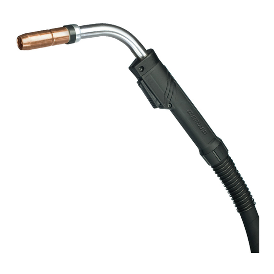
Description
Semi-Automatic, Water-Cooled,
400 amp, MIG (GMAW) Welding
T-Gun
TM
Phone:
1-855-MIGWELD (644-9353)
1-519-737-3000
Fax:
708-946-6726
For more information, visit us at BernardWelds.com
TG408 – REV E
March 2018
(US & Canada)
(International)
Advertisement
Table of Contents

Related Manuals for Bernard T-Gun


Summary of Contents for Bernard T-Gun
- Page 1 TG408 – REV E March 2018 Processes MIG (GMAW) Welding Description Semi-Automatic, Water-Cooled, 400 amp, MIG (GMAW) Welding T-Gun Semi-Automatic MIG Guns TECHNICAL GUIDE Bernard A Division of Miller Electric Mfg. LLC Phone: 1-855-MIGWELD (644-9353) (US & Canada) 449 West Corning Road...
-
Page 2: Table Of Contents
TABLE OF CONTENTS WARRANTY………………………………………………………………………………………………………………3 SECTION 1 - SAFETY PRECAUTIONS FOR GMAW WELDING GUNS – READ BEFORE USING…………………………….4 1-1 SYMBOL USAGE……………………………………………………………………………………………………...4 1-2 ARC WELDING HAZARDS…………………………………………………………………………………....4 1-3 PROPOSITION 65 WARNINGS………………………………………………………………………………………..6 1-4 PRINCIPAL SAFETY STANDARDS…………………………………………………………………………....6 1-5 EMF INFORMATION…………………………………………………………………………………………………..6 SECTION 2 – INSTALLATION …………………………………………………………………………………………….7 2-1 INSTALLING QUICK CONNECT BLOCK TO FEEDER…………………………………………………………………..7 2-2 INSTALLING GUN TO QUICK CONNECT BLOCK……………………………………………………………………...7 2-3 INSTALLING POWER PIN TO GUN…………………………………………………………………………………...8... -
Page 3: Warranty
OF SELLER. Genuine Bernard and Tregaskiss parts must be used for safety and performance reasons or the warranty above shall not be valid. Warranty shall not apply if accident, abuse, or misuse damages a product, or if a product is modified in any way except... -
Page 4: Section 1 - Safety Precautions For Gmaw Welding Guns - Read Before Using
SECTION 1 - SAFETY PRECAUTIONS FOR GMAW WELDING GUNS – READ BEFORE USING Protect yourself and others from injury — read, follow, and save these important safety precautions and operating instructions. 1-1 Symbol Usage DANGER! − Indicates a hazardous situation which, if not avoided, will result in death or serious injury. - Page 5 BUILDUP OF GAS can injure or kill. WELDING WIRE can injure. • Keep hands and body away from gun tip • Shut off compressed gas supply when trigger is pressed. when not in use. • Always ventilate confined spaces or use approved air-supplied respirator.
-
Page 6: Proposition 65 Warnings
1-3 Proposition 65 Warnings WARNING: This product can expose you to chemicals including lead, which are known to the state of California to cause cancer and birth defects or other reproductive harm. For more information, go to www.P65Warnings.ca.gov. 1-4 Principal Safety Standards Safe Handling of Compressed Gases in Cylinders, CGA Safety in Welding, Cutting, and Allied Processes, ANSI Pamphlet P-1, from Compressed Gas Association, 14501... -
Page 7: Section 2 - Installation
SECTION 2 – INSTALLATION 2-1 INSTALLING QUICK CONNECT BLOCK TO FEEDER STEP #1 • Insert the correct feeder adaptor liner for desired wire diameter (2 provided) flush with the threaded end of the feeder adaptor. • Tighten set screw. Thread feeder adaptor into Quick Connect Block and •... -
Page 8: Installing Power Pin To Gun
- Insert control plug into feeder. carefully insert connector into female adaptor - Feed welding wire into power pin by hand and tighten Euro hand nut or Bernard-style and tighten drive rolls. locking collar. - On Lincoln it is necessary to connect gas •... -
Page 9: Section 3 - Maintenance
SECTION 3 – MAINTENANCE 3-1 TREGASKISS™ NOZZLE AND TOUGH LOCK™ CONSUMABLES HEAVY DUTY HEAVY DUTY HEAVY DUTY NOZZLE NECK TOUGH LOCK TOUGH LOCK VARIOUS LENGTHS AVAILABLE INSULATOR CONTACT TIP RETAINING HEAD IMPORTANT: • Neck Insulator must be in place before welding to maintain insulation of neck armor. •... -
Page 10: Neck Replacement
3-3 NECK REPLACEMENT HANDLE FRONT LOCKING CAP STEP #1 • Remove liner from gun. • Twist handle locking caps. • Pull handle locking caps away from HANDLE REAR LEADS LOCKING CAP handle. • Remove Philips screw. SWITCH LEAD • Separate handle. CONNECTORS •... -
Page 11: Liner Replacement
3-4 LINER REPLACEMENT NOTE: For guns equipped with thread-in power pins, Bernard, or Euro-connectors, the procedure is the same. On Miller-style guns, liner is held captive by a guide cap which must be removed and replaced when changing liner. STEP #1 NOTE: Ensure power supply is off and gun is removed from feeder before proceeding. -
Page 12: Cable Assembly Replacement
3-5 CABLE ASSEMBLY REPLACEMENT STEP #1 MOUNTING SCREWS • Remove nozzle, tip and retainer. • Take out rear housing screws and pull out liner. STEP #2 POWER & RED REAR WATER LINE BLUE WATER LINE 2-PIECE WHITE CONDUIT LINE POWER PIN •... - Page 13 HANDLE FRONT LOCKING CAP HANDLE REAR LOCKING CAP WATER LINES (RED & BLUE) & POWER LINE NECK OUTER JACKET WHITE CONDUIT LINE STEP #3 • On front of gun, release front handle from neck. • Remove outer jacket by pulling outer jacket only from rear of gun; all that remains are the inner hoses attached to the neck and switch lead wires.
- Page 14 STEP #6 At rear of gun, slide rear handle up over outer jacket. • Attach rear power block to power cable. • Attach the gas line and water line with new clamps and crimp to power block. STEP #7 • Slide rear handle to rear power block and secure with mounting screws.
-
Page 15: Section 4 − Technical Data
SECTION 4 − TECHNICAL DATA 4-1 NECK DIMENSIONS NECK ANGLE INCHES INCHES INCHES 445-45 45° 5.63 142.95 4.02 102.16 63.5 445-60 60° 4.99 126.75 5.14 130.56 63.5 4-2 GUN AMPERAGE RATINGS 100% DUTY CYCLE 60% DUTY CYCLE MODEL MIXED MIXED NOTE: Ratings are based on tests that comply with IEC 60974-7 standards. -
Page 16: Feeder Adaptors
5-4 CONNECTOR OPTIONS Euro Connector option - for European style feeders adaptors for Euro Connector option - for European style feeders and feeder and 400 amp T-Gun MIG Guns Feeder adaptors for 400 amp T-Gun MIG Guns. PART # DESCRIPTION PART #... -
Page 17: Section 6 - Troubleshooting
SECTION 6 – TROUBLESHOOTING PROBLEM POSSIBLE CAUSE • CONDUIT LINER CLOGGED OR KINKED POOR WIRE FEED • INCORRECT LINER SIZE OR CONTACT TIP • LINER CUT TOO SHORT AND NOT SEATING PROPERLY IN GAS DIFFUSER • DRIVE ROLLS TOO TIGHT RESULTING IN SCORING OF WELDING WIRE •... -
Page 18: Section 7 − Exploded View And Parts List
SECTION 7 − EXPLODED VIEW AND PARTS LIST Numbers this column correspond to exploded view images above. ITEM PART # DESCRIPTION ITEM PART # DESCRIPTION STANDARD NOZZLES (SELF-INSULATED) 404-20 TREGASKISS™ TOUGH LOCK™ RETAINING HEAD FOR HD TIPS 401-40-38 SUPER TAPERED NOZZLE - 3/8" BORE (BRASS) 454-1-2 RETAINING RING 401-4-38... - Page 19 PART # DESCRIPTION PART # DESCRIPTION 412-8 SWITCH LEAD CONNECTOR 416-15 EURO HOUSING BLANK (C/W SCREWS) 416-5 CONTROL HOUSING (C/W SCREWS) 642-XX OUTER JACKET ASSEMBLY 411-3M MOUNTING SCREWS (METRIC) 320-5 JACKET BUSHING 320-4 REAR HANDLE CAP FEEDER ADAPTOR REQUIREMENTS (SOLD SEPARATELY) 663-1-XX OUTER JACKET QUICK CONNECT BLOCK ASSEMBLY TWECO #4...
-
Page 20: Section 8 - Ordering Information
400 amp 445-60 401-6-62 404-20 403-20-XX Bernard Phone: 1-855-MIGWELD (644-9353) (US & Canada) A Division of Miller Electric Mfg. LLC 1-519-737-3000 (International) Fax: 708-946-6726 449 West Corning Road Beecher, Illinois 60401 USA For more information, visit us at BernardWelds.com ©2018 Bernard...