Table of Contents
Advertisement
Advertisement
Table of Contents

Related Manuals for Datalogic DS2100


Summary of Contents for Datalogic DS2100
- Page 1 DS2100 Installation Manual...
- Page 3 DS2100 INSTALLATION MANUAL...
- Page 4 ALL RIGHTS RESERVED Datalogic reserves the right to make modifications and improvements without prior notification. Datalogic shall not be liable for technical or editorial errors or omissions contained herein, nor for incidental or consequential damages resulting from the use of this material.
-
Page 5: Table Of Contents
CONTENTS GUIDE TO INSTALLATION ................. v GENERAL VIEW ..................vi SAFETY PRECAUTIONS................vii Laser Safety....................vii Power Supply....................ix GENERAL FEATURES ................1 Introduction ....................1 Description ....................1 Available Models................... 3 GFC-2100 Accessory Installation..............4 INSTALLATION.................... 5 Package Contents..................5 Mechanical Installation.................. 6 Electrical Connections .................. - Page 6 MAINTENANCE..................33 Cleaning...................... 33 TECHNICAL FEATURES ................34...
-
Page 7: Guide To Installation
GUIDE TO INSTALLATION The following can be used as a checklist to verify all of the steps necessary for complete installation of the DS2100 scanner. 1) Read all information in the section "Safety Precautions” at the beginning of this manual. -
Page 8: General View
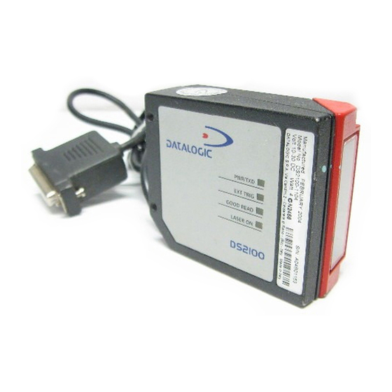
GENERAL VIEW DS2100 Figure A Mounting Holes Power On / Data TX LED Warning and Device Class Labels Laser On LED Accessory Mounting Holes Good Read LED Laser Beam Output Window External Trigger LED... -
Page 9: Safety Precautions
LASER SAFETY The following information is provided to comply with the rules imposed by international authorities and refers to the correct use of the DS2100 scanner. Standard Regulations This scanner utilizes a low-power laser diode. Although staring directly at the laser beam momentarily causes no known biological damage, avoid staring at the beam as one would with any very strong light source, such as the sun. - Page 10 Warning labels indicating exposure to laser light and the device classification are applied onto the body of the scanner (Figure A, 6). LASER LIGHT DO NOT STARE INTO BEAM CLASS 2 LASER PRODUCT MAX. OUTPUT RADIATION 1 mW EMITTED WAVE LENGTH 630~680 nm TO IEC 825-1 (1993) CAUTION - LASER LIGHT WHEN OPEN AVOID EXPOSURE TO BEAM...
-
Page 11: Power Supply
POWER SUPPLY - This product is intended to be installed by Qualified Personnel only. - Models DS2100-X0XX, DS2100-X1XX: This accessory device is intended to be supplied by a UL Listed Power Unit with «Class 2» or LPS power source which supplies power directly to the scanner via the 25-pin connector. -
Page 13: General Features
GENERAL FEATURES INTRODUCTION The DS2100 laser scanner satisfies the most advanced needs of a wide range of users. It has been developed focusing on the realistic requirements of its target market. The outstanding result is an extremely compact, cost-effective and easy to use industrial scanner. - Page 14 • low power consumption. The DS2100 uses a solid state laser diode as a light source; the light emitted has a wavelength between 630 and 680 nm. Refer to the section “Safety precautions” at the beginning of this manual for information on laser safety.
-
Page 15: Available Models
GENERAL FEATURES AVAILABLE MODELS The DS2100 scanner is available in versions that differ in regard to the following parameters: • Resolution • Interface module and termination of the cable • Linear or raster models • Performance The following models are therefore available:... -
Page 16: Gfc-2100 Accessory Installation
DS2100 GFC-2100 ACCESSORY INSTALLATION GFC-2100 is a 90° deflection mirror available on request for DS2100. The installation of the 90° deflection mirror is very easy (Figure 1). Avoid any contact with the deflection mirror, mirrored rotor, the lenses or other optical components, otherwise the performance of the reader will be reduced. -
Page 17: Installation
INSTALLATION INSTALLATION PACKAGE CONTENTS Verify that the DS2100 reader and all the parts supplied with the equipment are present and intact when opening the packaging; the list of parts includes: • DS2100 reader with cable • Installation manual • Bar code test chart (PCS = 0.9) •... -
Page 18: Mechanical Installation
DS2100 MECHANICAL INSTALLATION DS2100 can be installed to operate in different positions. The four screw holes (M4 x 5) on the body of the reader are for mechanical fixture (Figure A, 1). The diagrams below give the overall dimensions of the scanner and mounting bracket and may be used for installation. -
Page 19: Electrical Connections
INSTALLATION ELECTRICAL CONNECTIONS Several DS2100 models are equipped with a cable terminated by a 25-pin female D- sub connector for connection to the power supply and input/output signals. The details of the connector pins are indicated in the following table. - Page 20 CTS232 RX485- CLIN- SGND SGND SGND Some DS2100 models are equipped with a 9-pin female connector. The details of the connector pins are indicated in the following table: 9-pin connector pinout Name Function Power supply input voltage + Power supply input voltage -...
-
Page 21: Power Supply
DS2100 depending on the DS2100 model (see par. 1.3). A passive 20-mA Current Loop interface is available if the optional INT-22 accessory is installed. This accessory interface replaces the main serial interface of the DS2100 model. The INT-22 accessory board is not available for DS2100-X3X0 models. -
Page 22: Rs232 Interface
CTS232 clear to send GND/SGND signal ground It is always advisable to use shielded cables. The overall maximum cable length must be less than 15 m (49.2 ft). DS2100 9-pin DS2100 25-pin USER INTERFACE TX232 TX232 RX232 RX232... -
Page 23: Rs485 Full-Duplex Interface
IDLE IDLE Figure 8 - RS232 control signals If the RTS/CTS handshaking protocol is enabled, the DS2100 activates the RTS232 output to indicate a message is to be transmitted. The receiving unit activates the CTS232 input to enable the transmission. -
Page 24: Rs485 Half-Duplex Interface
The RS485 half-duplex (3 wires + shield) interface is used for polled communication protocols. It can be used in a master/slave layout or for Multidrop connections with a Datalogic Multiplexer, (see par. 2.5.4 and 2.5.5) exploiting a proprietary protocol based on polled mode called MUX32 protocol, where a master device polls slave devices to collect data. - Page 25 In a Multiplexer layout or for slaves, the Multidrop address must also be set via serial channel by the WinHost utility or by ESC sequences. Figure 11 shows a multidrop configuration with DS2100 scanners connected to a Multiplexer. 120 Ohm...
-
Page 26: Ma Current Loop Interface (Int-22 Accessory Only)
DS2100 20 mA Current Loop Interface (INT-22 Accessory Only) When the INT-22 accessory board is installed, the DS2100 is equipped with a 20 mA passive current loop. The following pins of the 25-pin connector are used: Connector Name Function 25-Pin... -
Page 27: Auxiliary Rs232 Interface
The RTSAUX and CTSAUX signals control data transmission and synchronize the connected devices. If the RTS/CTS handshaking protocol is enabled, the DS2100 activates the RTSAUX output to indicate a message is to be transmitted. The... -
Page 28: Code Verifier
DS2100 Code Verifier If the DS2100 is used as a Code Verifier, it is possible to indicate to the scanner what code to store as the verifier code by means of an external hardware input. The Code Verifier parameter must be enabled and the configuration parameters to allow correct Code Type reading must be saved to the scanner in order to read the verifier code. - Page 29 DS2100 25-pin EXTERNAL TRIGGER + 5V EXT TRIG+ EXT TRIG+ EXT TRIG- EXT TRIG- Signal Ground Figure 15 - Input NPN command using DS2100 power Vext 30 Vdc max. DS2100 9-pin DS2100 25-pin EXTERNAL TRIGGER + 5V Signal EXT TRIG+...
-
Page 30: Outputs
By default, OUT1 is associated with the No Read event, which activates when the code signaled by the external trigger is not decoded, and OUT2 is associated with the Right event, which activates when the code is correctly decoded. DS2100 25-pin USER INTERFACE Vext 40 Vdc max... -
Page 31: Positioning
INSTALLATION POSITIONING The DS2100 scanner is able to decode barcode labels at a variety of angles, however significant angular distortion may degrade reading performance. When mounting the DS2100 take into consideration these three ideal label position angles: Pitch 0°, Skew 10° to 30° and Tilt 0°. -
Page 32: Typical Layouts
DS2100 The Tilt angle is represented by the value T in Figure 21. Position the reader in order to minimize the Tilt angle. Figure 21 - Tilt angle TYPICAL LAYOUTS The following typical layouts refer to system hardware configurations. Dotted lines in the figures refer to optional hardware configurations within the particular layout. -
Page 33: Point-To-Point
Trigger (photoelectric sensor) when the object enters its reading zone. DS2100 Terminal Host Main serial interface Auxiliary serial interface (Local Echo) External Trigger (for On-Line mode) Figure 22 – Point-to-point layout This is the only layout available for DS2100-X3XX models. -
Page 34: Pass-Through
Pass-through mode allows two or more devices to be connected to a single external serial interface. Each DS2100 transmits the messages received by the Auxiliary interface onto the Main interface. All messages will be passed through this chain to the host. -
Page 35: Rs232 Master/Slave
9 slaves connected together. The Slave scanners use RS232 only on the main and auxiliary serial interfaces. Each slave DS2100 transmits the messages received by the auxiliary interface onto the main interface. All messages will be passed through this chain to the Master. -
Page 36: Rs485 Master/Slave
DS2100 2.5.4 RS485 Master/Slave The RS485 master/slave connection is used to collect data from several scanners to build a multi-point or a multi-sided reading system; there can be one master and up to 5 slaves connected together. The slave scanners are connected together using RS485 half-duplex on the main serial interface. -
Page 37: Multiplexer Layout
INSTALLATION 2.5.5 Multiplexer Layout Each scanner is connected to a Multiplexer (for example MX4000) with the RS485 half-duplex main interface. Host Main interface Auxiliary interface (Local Echo) MX4000 External Trigger (for On-Line mode) Figure 26 - Multiplexer layout The auxiliary serial interface can be used in Local Echo mode to control any single scanner (visualize collected data) or to configure it using the WinHost utility or Host Mode programming procedure. -
Page 38: Reading Features
DS2100 READING FEATURES The number of scans performed on the code by the DS2100 and therefore the decoding capability is influenced by the following parameters: • number of scans per second • code motion speed • label dimensions • scan direction with respect to code motion At least 5 scans during the code passage should be allowed to ensure a successful read. -
Page 39: Picket-Fence Mode
READING FEATURES For example, the DS2100 (350 scans/sec.) for a 25 mm high code moving at 500 mm/s performs: [(25/500) * 350] - 2 = 15 effective scans. PICKET-FENCE MODE If scanning is parallel to the code motion, (Figure 28), the number of effective scans... -
Page 40: Performance
DS2100 PERFORMANCE The DS2100 scanner is available in different versions according to the reading performance. Version Max Code Resolution Speed mm (mils) scans/s 1XX0 0.20 (8) 1XX4 0.20 (8) 2XX0 0.15 (6) 2XX4 0.12 (5) Version Reading Distance 1XX0 40 mm (1.6 in) - 300 mm (11.8 in) on 0.50 mm (20 mils) codes 1XX4 45 mm (1.8 in) - 300 mm (11.8 in) on 0.50 mm (20 mils) codes... -
Page 41: Reading Diagrams
READING FEATURES READING DIAGRAMS DS2100-1XX0 (Standard Resolution, 350 scans/s) (in) (mm) 80 100 120 140 160 180 200 220 240 260 ≥ 0.50 mm 0.20 mm 0.30 mm (8 mils) (12 mils) (20 mils) (mm) (in) NOTE: (0,0) is the center of the laser beam output window. - Page 42 DS2100 DS2100-2XX0 (High resolution, 350 scans/s) (in) (mm) 90 100 110 120 130 ≥ 0.30 mm (12 mils) 0.15 mm (6 mils) 0.20 mm (8 mils) (mm) (in) NOTE: (0,0) is the center of the laser beam output window. CONDITIONS...
- Page 43 READING FEATURES DS2100-1XX4 Testarossa™ (in) (mm) 80 100 120 140 160 180 200 220 240 260 ≥ 0.50 mm 0.20 mm 0.30 mm (8 mils) (12 mils) (20 mils) (mm) (in) NOTE: (0,0) is the center of the laser beam output window.
- Page 44 DS2100 DS2100-2XX4 Testarossa™ - High Resolution (in) (mm) 90 100 110 120 130 ≥ 0.20 mm (8 mils) 0.12 mm (5 mils) 0.15 mm (6 mils) (mm) (in) NOTE:(0,0) is the center of the laser beam output window. CONDITIONS Code = Interleaved 2/5 or Code 39 = 0.90...
- Page 45 Repeat the operation frequently in particularly dirty environments. Use soft material and alcohol to clean the window and avoid any abrasive substances. Clean the window of the DS2100 when the scanner is turned off or, at least, when the laser beam is deactivated. WARNING...
- Page 46 DS2100 TECHNICAL FEATURES DS2100-XXX0 DS2100-XXX4 Testarossa™ Standard High Standard High Resolution Resolution Resolution Resolution ELECTRICAL FEATURES Power Supply voltage 10 to 30 Vdc Power consumption max. Serial Interfaces (depends on model) Main RS232; RS485 Full-duplex / Half-duplex; 20 mA C.L. (only with INT-22 accessory)
- Page 47 TECHNICAL FEATURES SOFTWARE FEATURES READABLE CODE SYMBOLOGIES • EAN/UPC (including Add-on 2 and Add-on 5) • Code 93 • 2/5 Interleaved • Code 128 • Code 39 (Standard and Full ASCII) • EAN 128 • Codabar • Pharmacode Other symbologies available on request. Code Selection up to six different codes during one reading phase Decoding Safety...
- Page 48 40012 - Lippo di Calderara Bologna - Italy declare under our sole responsibility that the product DS2100-XXXX, Laser Scanner and all its models to which this declaration relates is in conformity with the following standards or other normative documents EN 55022, August 1994:...