Table of Contents
Advertisement
www.nordictrack.com
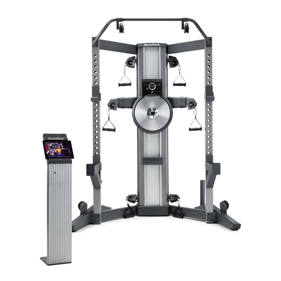
Model No. NTSY14016.0
Serial No.
Write the serial number in the space
above for reference.
Serial Number
Decal
ACTIVATE YOUR
WARRANTY
To register your product and
activate your warranty today, go
to www.nordictrackservice.com/
registration.
CUSTOMER CARE
For service at any time, go to
www.nordictrackservice.com.
Or call 1-866-608-1798
Mon.–Fri. 6 a.m.–6 p.m. MT
Sat. 8 a.m.–12 p.m. MT
Please do not contact the store.
CAUTION
Read all precautions and
instructions in this manual before
using this equipment. Keep this
manual for future reference.
USER'S MANUAL
Advertisement
Table of Contents

Related Manuals for NordicTrack NTSY14016.0


Summary of Contents for NordicTrack NTSY14016.0
- Page 1 USER’S MANUAL Model No. NTSY14016.0 Serial No. Write the serial number in the space above for reference. Serial Number Decal ACTIVATE YOUR WARRANTY To register your product and activate your warranty today, go to www.nordictrackservice.com/ registration. CUSTOMER CARE For service at any time, go to www.nordictrackservice.com.
-
Page 2: Table Of Contents
Apply the decal in the location shown. Note: The decal(s) may not be shown at actual size. NORDICTRACK is a registered trademark of ICON Health & Fitness, Inc. The BLUETOOTH word mark and ®... -
Page 3: Important Precautions
IMPORTANT PRECAUTIONS WARNING: To reduce the risk of serious injury, read all important precautions and instructions in this manual and all warnings on your strength system before using your strength system. ICON assumes no responsibility for personal injury or property damage sustained by or through the use of this product. - Page 4 STANDARD SERVICE PLANS...
-
Page 5: Before You Begin
BEFORE YOU BEGIN Congratulations for selecting the revolutionary after reading this manual, please see the front cover NORDICTRACK FUSION CST strength system. The of this manual. To help us assist you, note the product ® FUSION CST strength system is unlike any ordinary model number and serial number before contacting us. -
Page 6: Assembly
ASSEMBLY • Due to the size and weight of the strength system, • In addition to the included tool(s), assembly assembly requires two or three persons. requires the following tools: Drill with a 1/4" bit or a 7/8" bit • Place all parts in a cleared area and remove the packing materials. - Page 7 Wall Bracket Assembly • IMPORTANT: Obtain professional advice and have a qualified person install the brackets to ensure adequate support. • IMPORTANT: Do not fasten the brackets to a drywall surface or to a cinder block surface. • The location on the wall to which the brackets are fastened must be capable of supporting a working load of 600 lbs.
- Page 8 WARNING: Serious injury could result if the Slide Brackets (60) or Wall Brackets (61) are improperly installed. Obtain professional advice and have a qualified person install the Slide Brackets or Wall Brackets. Do not fasten the Slide Brackets or Wall Brackets to a drywall surface or to a cinder block surface.
- Page 9 2. Align a Slide Bracket (60) along the centers of the wall studs. Using your pencil, mark the Wood Studs locations of the slots on the wall studs. Then, remove the Slide Bracket. Repeat these actions for the other Slide Bracket (60).
- Page 10 3. See the upper drawing. Slide a Wall Bracket (61) onto each side of a Slide Bracket (60). Align the Slide Bracket (60) assembly along the centers of the wall studs. Adjust the Wall Brackets (61) as needed. Using your pencil, mark the locations of the slots on the wall studs.
- Page 11 Strength System Assembly 4. Orient the Tower Top Cover (2) as shown, and press it onto the top of the Frame (1). 5. With the help of one or two other persons, move the strength system near the wall and align the four Tower Brackets (62) on the strength system with the two Slide Brackets (60) on the wall.
- Page 12 6. Firmly tighten the four indicated M10 x 20mm Bolts (102) (only one side is shown).
- Page 13 7. Identify the four Slide Covers (63) and the four Wall Covers (64). Slide the Slide Cover or 63 or 64 the Wall Cover that best fits onto each Slide Bracket (60). Note: Save the unused Slide Covers (63) or Wall Covers (64) in case you need to mount the strength system differently in the future.
- Page 14 9. Attach a Handle (37) to a Rope End (35) with a Clip (36). Attach the other Handles (37) in the same way.
- Page 15 10. Attach the Right Squat Leg (44) to the right side of the Frame (1) with four M10 x 25mm Hex Screws (133); start all the Hex Screws, and then tighten them. Attach the Left Squat Leg (66) in the same way.
- Page 16 12. Plug the Power Adapter (126) into the receptacle on the rear of the strength system. Note: To plug the Power Adapter (126) into an outlet, see HOW TO PLUG IN THE POWER ADAPTER on page 18. 13. Go to www.nordictrackservice.com/ registration on your computer and register your product.
-
Page 17: The Chest Heart Rate Monitor
THE CHEST HEART RATE MONITOR HOW TO PUT ON THE HEART RATE MONITOR • Store the heart rate monitor in a warm, dry place. Do not store the heart rate monitor in a plastic bag or If the heart rate monitor looks like the one shown in other container that may trap moisture. -
Page 18: How To Use The Strength System
HOW TO USE THE STRENGTH SYSTEM This section explains how to adjust the strength system. See the EXERCISE GUIDELINES on page 25 and page 26 for important information about how to get the most benefit from your exercise program. Also, refer to the accompanying exercise guide to see the correct form for each exercise. - Page 19 HOW TO USE THE TABLET HOLDER IMPORTANT: The Tablet Holder (68) is designed for use with most full-size tablets. Do not place any other electronic device or object in the Tablet Holder. Do not set anything on top of the Tablet Holder.
- Page 20 CONSOLE DIAGRAM FEATURES OF THE CONSOLE HOW TO USE THE CONSOLE 1. Press the power button to turn on the console. The advanced console offers an array of features designed to make your workouts more effective and enjoyable. When you turn on the console, the display will turn on.
- Page 21 Resistance—This Average Maximum display will show the Power Output resistance level for a (Ave)—This display few seconds each time will show your aver- the resistance level age maximum power changes. output in watts for your workout. Watts—This display will show your approxi- Note: If you do not resume exercising after a few mate maximum power moments, the workout information will be reset and...
-
Page 22: Fcc Information
FCC INFORMATION This equipment has been tested and found to comply with the limits for a Class B digital device, pursuant to part 15 of the FCC Rules. These limits are designed to provide reasonable protection against harmful interference in a residential installation. This equipment generates, uses, and can radiate radio frequency energy and, if not installed and used in accordance with the instructions, may cause harmful interference to radio communications. -
Page 23: Maintenance And Troubleshooting
MAINTENANCE AND TROUBLESHOOTING HOW TO MAINTAIN THE STRENGTH SYSTEM See assembly step 5 on page 11. Remove the four M10 x 20mm Patch Screws (101) and M10 Star Regular maintenance is important for optimal Washers (119) from the four Tower Brackets (62). performance and to reduce wear. - Page 24 HOW TO TIGHTEN THE ROPES The ropes may stretch over time. If there is slack in the ropes before resistance is felt, the ropes should be tightened. To tighten the ropes, first unplug the power adapter, and then follow the steps below. See assembly step 11 on page 15.
-
Page 25: Cardio Exercise Guidelines
CARDIO EXERCISE GUIDELINES Burning Fat—To burn fat effectively, you must exer- WARNING: cise at a low intensity level for a sustained period of Before beginning this time. During the first few minutes of exercise, your or any exercise program, consult your physi- body uses carbohydrate calories for energy. -
Page 26: Strength Exercise Guidelines
STRENGTH EXERCISE GUIDELINES FOUR TYPES OF STRENGTH WORKOUTS to determine the appropriate length of time for each workout, and the numbers of repetitions and sets to Note: A “repetition” is one complete cycle of an complete. Progress at your own pace and be sensitive exercise, such as one sit-up. - Page 27 SUGGESTED STRETCHES The correct form for several basic stretches is shown at the right. Move slowly as you stretch; never bounce. 1. Toe Touch Stretch Stand with your knees bent slightly and slowly bend forward from your hips. Allow your back and shoulders to relax as you reach down toward your toes as far as possible.
-
Page 28: Part List
PART LIST Model No. NTSY14016.0 R1216A Key No. Qty. Description Key No. Qty. Description Frame Short Sensor Bracket Tower Top Cover 201" Rope Spring Ankle Strap Spring Cover Arm Pulley Spacer Disc Cover Small Pulley Resistance Disc Large Pulley Resistance Axle... - Page 29 Key No. Qty. Description Key No. Qty. Description M10 x 20mm Patch Screw Mounted Zip Tie M10 x 20mm Bolt Sensor Wire 3/8" x 3" Screw Extension Wire 3/8" x 1 1/4" Washer #8 x 5/8" Tek Screw M10 x 100mm Toggle Bolt Main Wire M8 Jam Nut Power Adapter...
-
Page 30: Exploded Drawing
EXPLODED DRAWING A Model No. NTSY14016.0 R1216A... - Page 31 EXPLODED DRAWING B Model No. NTSY14016.0 R1216A...
-
Page 32: Ordering Replacement Parts
ORDERING REPLACEMENT PARTS To order replacement parts, please see the front cover of this manual. To help us assist you, be prepared to provide the following information when contacting us: • the model number and serial number of the product (see the front cover of this manual) •...