Advertisement
Table of Contents
- 1 Table of Contents
- 2 Warning Decal Placement
- 3 Important Precautions
- 4 Before You Begin
- 5 Part Identification Chart
- 6 Assembly
- 7 The Chest Heart Rate Monitor
- 8 How to Use the Strength System
- 9 Fcc Information
- 10 Maintenance and Troubleshooting
- 11 Cardio Exercise Guidelines
- 12 Strength Exercise Guidelines
- 13 Part List
- 14 Exploded Drawing
- 15 Ordering Replacement Parts
- 16 Limited Warranty
- Download this manual
nordictrack.com
Model No. NTSY24918F.0
Serial No.
Write the serial number in the space
above for reference.
Serial
Number
Decal
ACTIVATE YOUR
WARRANTY
To register your product and
activate your warranty today,
go to my.nordictrack.com.
CUSTOMER CARE
For service at any time, go to
support.nordictrack.com.
Or call 1-800-TO-BE-FIT
(1-800-862-3348)
Mon.–Fri. 6 a.m.–6 p.m. MT
Sat. 8 a.m.–12 p.m. MT
Please do not contact the store.
CAUTION
Read all precautions and
instructions in this manual before
using this equipment. Keep this
manual for future reference.
USER'S MANUAL
Advertisement
Table of Contents

Related Manuals for NordicTrack FUSION CST PRO


Summary of Contents for NordicTrack FUSION CST PRO
- Page 1 Serial Number Decal ACTIVATE YOUR WARRANTY To register your product and activate your warranty today, go to my.nordictrack.com. CUSTOMER CARE For service at any time, go to support.nordictrack.com. Or call 1-800-TO-BE-FIT (1-800-862-3348) Mon.–Fri. 6 a.m.–6 p.m. MT Sat. 8 a.m.–12 p.m. MT Please do not contact the store.
-
Page 2: Table Of Contents
LIMITED WARRANTY............. . . Back Cover NORDICTRACK and IFIT are registered trademarks of ICON Health & Fitness, Inc. Android is a trademark of Google LLC. -
Page 3: Warning Decal Placement
WARNING DECAL PLACEMENT This drawing shows the location(s) of the warning decal(s). If a decal is missing or illegible, see the front cover of this manual and request a free replacement decal. Apply the decal in the location shown. Note: The decal(s) may not be shown at actual size. -
Page 4: Important Precautions
IMPORTANT PRECAUTIONS WARNING: To reduce the risk of serious injury, read all important precautions and instructions in this manual and all warnings on your strength system before using your strength system. ICON assumes no responsibility for personal injury or property damage sustained by or through the use of this product. - Page 5 STANDARD SERVICE PLANS...
-
Page 6: Before You Begin
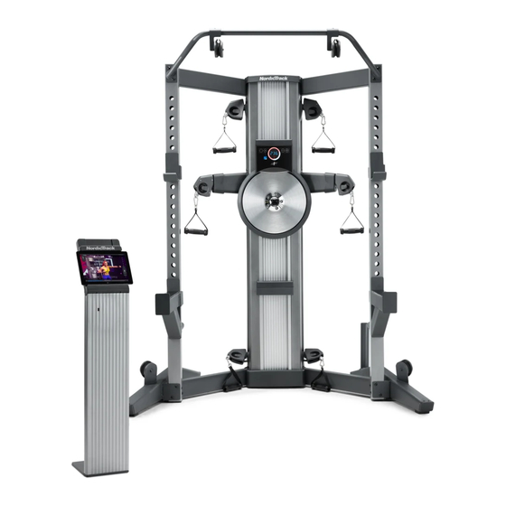
FUSION CST PRO strength system. of this manual. To help us assist you, note the product ® The FUSION CST PRO strength system is unlike any model number and serial number before contacting us. ordinary strength system. Whether your goal is to tone... -
Page 7: Part Identification Chart
PART IDENTIFICATION CHART Use the drawings below to identify the small parts needed for assembly. The number in parentheses below each drawing is the key number of the part, from the PART LIST near the end of this manual. The number following the key number is the quantity needed for assembly. -
Page 8: Assembly
To avoid are marked “R” or “Right.” damaging parts, do not use power tools. 1. Go to my.nordictrack.com on your computer and register your product. • documents your ownership • activates your warranty •... - Page 9 2. Tip: To protect the floor or carpet from damage, place a mat under the strength system. Attach the Right Lower Stabilizer (130) to the right side of the Frame (1) with four M10 x 25mm Hex Screws (101); start all the Hex Screws, but do not fully tighten them yet.
- Page 10 3. Attach the Right Upper Stabilizer (146) to the right side of the Frame (1) with two M10 x 35mm Screws (95); start both Screws, but do not fully tighten them yet. Attach the Left Upper Stabilizer (151) in the same way.
- Page 11 4. Orient the Right Upright (150) as shown. Attach the Right Upright (150) to the Right Upper Stabilizer (146) with an M10 x 93mm Screw (102). Make sure to insert the Screw into the lower hole (A); do not fully tighten the Screw yet.
- Page 12 5. Attach the Right Leg (44) to the Right Upright (150) and the Right Lower Stabilizer (130) with two M10 x 73mm Screws (143), two M10 x 93mm Screws (102), and two M10 x 98mm Screws (140); start all the Screws, but do not fully tighten them yet.
- Page 13 6. Slide the Pull-up Bar (147) onto the M10 x 93mm Screws (102) in the Left and Right Uprights (149, 150) that you attached in step 4. Attach the Pull-up Bar (147) with two additional M10 x 93mm Screws (102), start both Screws, but do not fully tighten them yet.
- Page 14 8. Press the Front and Rear Bottom Covers (67, 109) into place as shown. 9. Tip: Avoid pinching the Rope (105). With the help of another person, pivot the Right Tower Arm (153) upward and secure it to the Frame (1) with an M10 x 30mm Screw (100).
- Page 15 10. Tighten a Storage Tube (144) into the Right Upright (150). Attach the other Storage Tube (144) to the Left Upright (not shown) in the same way. 11. Orient a Weight Rest (141) as shown, insert it into an adjustment hole in the Left Upright (149), and rotate it in the direction shown by the arrow.
- Page 16 12. Attach a Handle (37) to a Rope End (35) with a Clip (36). Attach the other Handles (37) in the same way. 13. Orient a Pulley Bracket (60) as shown, and then insert the post on the Pulley Bracket into the desired adjustment hole in the Pull-up Bar (147).
- Page 17 14. Plug the Power Adapter (126) into the receptacle on the rear of the strength system. Note: To plug the Power Adapter (126) into an outlet, see HOW TO PLUG IN THE POWER ADAPTER on page 19. 15. Plug the Tablet Stand Power Wire (155) into a receptacle on the side or the rear of the Tablet Stand (15).
-
Page 18: The Chest Heart Rate Monitor
THE CHEST HEART RATE MONITOR HOW TO PUT ON THE HEART RATE MONITOR • Store the heart rate monitor in a warm, dry place. Do not store the heart rate monitor in a plastic bag or If the heart rate monitor looks like the one shown in other container that may trap moisture. -
Page 19: How To Use The Strength System
HOW TO USE THE STRENGTH SYSTEM This section explains how to adjust the strength system. See the EXERCISE GUIDELINES on page 28 and page 29 for important information about how to get the most benefit from your exercise program. Make sure that all parts are properly tightened each time the strength system is used. Replace any worn parts immediately. - Page 20 HOW TO USE THE TABLET HOLDERS IMPORTANT: The Tablet Holders (68) are designed for use with most full-size tablets. Do not place any other electronic device or object in the Tablet Holders. Do not set anything on top of the Tablet Holders. To insert a tablet into a Tablet Holder (68), slide it upward, set the tablet in the tray (A), and then pull the Tablet Holder downward over the top edge of the...
- Page 21 HOW TO USE THE UPPER PULLEYS Insert the post on a Pulley Bracket (60) into the desired adjustment hole in the Pull-up Bar (147). Pull an upper Handle (37) outward and route the Rope (not shown) over the pulley in the Pulley Bracket (60);...
- Page 22 HOW TO ADJUST THE WEIGHT RESTS AND THE WEIGHT SPOTTERS To adjust the height of the Weight Rests (141), first remove the Weight Rests from the Uprights (149, 150), insert them into the desired adjustment holes in the Uprights, and then rotate them into place.
- Page 23 Interactive iFit App heart rate monitor to the console, see page 25. Use the interactive iFit app to access the advanced features of your FUSION CST PRO. Note: If there is a sheet of plastic on the display, remove the plastic.
- Page 24 HOW TO USE THE CONSOLE 4. Wear the included chest heart rate monitor and measure your heart rate if desired. 1. Press the power button to turn on the console. You can wear the included chest heart rate moni- When you turn on the console, the display will turn tor to measure your heart rate.
-
Page 25: Fcc Information
HOW TO CONNECT YOUR HEART RATE MONITOR Note: The console may connect to your heart rate TO THE CONSOLE monitor automatically. If there is more than one com- patible heart rate monitor near the console, the console To use the included chest heart rate monitor, see THE will connect to the heart rate monitor with the strongest CHEST HEART RATE MONITOR on page 18. -
Page 26: Maintenance And Troubleshooting
MAINTENANCE AND TROUBLESHOOTING HOW TO MAINTAIN THE STRENGTH SYSTEM See EXPLODED DRAWING B on page 34. Identify the Rear Shroud (59). Remove the four #8 x 3/4" Regular maintenance is important for optimal Screws (86) and the Rear Shroud from the strength performance and to reduce wear. - Page 27 HOW TO TIGHTEN THE ROPES The ropes may stretch over time. If there is slack in the ropes before resistance is felt, the ropes should be tightened. To tighten the ropes, first unplug the power adapter, and then follow the steps below. See assembly step 8 on page 14.
-
Page 28: Cardio Exercise Guidelines
CARDIO EXERCISE GUIDELINES Burning Fat—To burn fat effectively, you must exer- WARNING: cise at a low intensity level for a sustained period of Before beginning this time. During the first few minutes of exercise, your or any exercise program, consult your physi- body uses carbohydrate calories for energy. -
Page 29: Strength Exercise Guidelines
STRENGTH EXERCISE GUIDELINES FOUR TYPES OF STRENGTH WORKOUTS to determine the appropriate length of time for each workout, and the numbers of repetitions and sets to Note: A “repetition” is one complete cycle of an complete. Progress at your own pace and be sensitive exercise, such as one sit-up. - Page 30 SUGGESTED STRETCHES The correct form for several basic stretches is shown at the right. Move slowly as you stretch; never bounce. 1. Toe Touch Stretch Stand with your knees bent slightly and slowly bend forward from your hips. Allow your back and shoulders to relax as you reach down toward your toes as far as possible.
-
Page 31: Part List
PART LIST Model No. NTSY24918F.0 R0420A Key No. Qty. Description Key No. Qty. Description Frame Short Sensor Bracket Tower Top Cover 201" Rope Spring Ankle Strap Spring Cover Arm Pulley Spacer Disc Cover Small Pulley Resistance Disc Medium Pulley Resistance Axle Shroud Cover Retention Ring Front Shroud... - Page 32 Key No. Qty. Description Key No. Qty. Description M10 x 25mm Hex Screw Chest Heart Rate Monitor M10 x 93mm Screw Right Lower Stabilizer 73" Rope USB Receptacle 82" Rope USB Bracket 169 1/2" Rope Roller M8 Jam Nut 1/4" x 1 3/8" Screw M8 x 30mm Bolt Carriage Bushing M8 x 30mm Patch Screw...
-
Page 33: Exploded Drawing
EXPLODED DRAWING A Model No. NTSY24918F.0 R0420A... - Page 34 EXPLODED DRAWING B Model No. NTSY24918F.0 R0420A...
- Page 35 EXPLODED DRAWING C Model No. NTSY24918F.0 R0420A...
-
Page 36: Ordering Replacement Parts
ORDERING REPLACEMENT PARTS To order replacement parts, please see the front cover of this manual. To help us assist you, be prepared to provide the following information when contacting us: • the model number and serial number of the product (see the front cover of this manual) •...