
Related Manuals for Nikon A1


Summary of Contents for Nikon A1
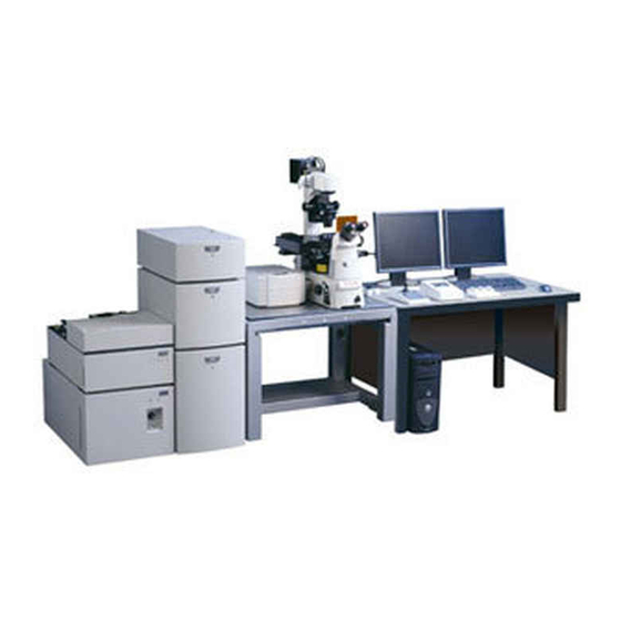
- Page 1 Confocal Microscope A1 Simple Instruction Manual (Ver.4.10) Nikon Corporation This document is subject to change for improvement without prior notice.
-
Page 2: Table Of Contents
CONTENTS Chapter 1. Introduction ............................... 3 Basic Operation ............................... 4 Chapter 2. Startup............................... 5 Chapter 3. Operation of the Microscope ........................7 Chapter 4. Capturing Color Images (Standard Detector) ..................13 Chapter 5. Capturing Multistained Images: Cross Talk Reduction (Standard Detector)..........18 Chapter 6. -
Page 3: Chapter 1. Introduction
Introduction Thank you for purchasing a Confocal Microscope A1. We are sure that the A1 will greatly contribute to your research with its many excellent functions. Read this manual carefully to maximize the effectiveness of these excellent functions. This manual also describes optional components. Since these are selective based on system configuration, some of them may not be provided for the system you purchased. -
Page 4: Basic Operation
Basic Operation A1 / Ti-E / PFS Motorized Stage / Piezo Z Stage / Intensilight This edition may have unavailable functions depending on model in use and option settings. -
Page 5: Chapter 2. Startup
Startup Chapter 2. Startup Turn on the power to the microscope. (1) Turn on the power to the motorized stage. POWER switch PO WE (2) Turn on the power to the piezo Z stage. POWER switch (3) Turn on the power to the halogen lamp (for visual diascopic microscopy). - Page 6 Note: When not only a confocal microscope is connected but also a camera, the Driver selection dialog box opens to select a driver. Select “Nikon Confocal” in the Driver selection dialog box and click the [OK] button.
-
Page 7: Chapter 3. Operation Of The Microscope
Operation of the Microscope Chapter 3. Operation of the Microscope Ti Remote Control Pad (Ti-RCP) Operation Pressing the icon of the motorized part you want to switch on the touch panel of Ti remote control pad displays a list of items installed in the each motorized part. Select an item you want to switch from the list. - Page 8 Chapter 3. Operation of the Microscope Microscopy Setting Dia illumination lamphouse Polarizer (Figure: D-LH/LC) Slide to put it into optical path. D filter NCB filter ND filter GIF filter Field diaphragm Filter sliders knob (both sides, four in total) Condenser mount Aperture diaphragm open/close lever Condenser focus knobs (both sides) Condenser centering knobs (both sides)
- Page 9 Chapter 3. Operation of the Microscope Operation Panel on the Microscope Ti-E Main Body Coarse/fine motion select switch Coarse Fine ExFine Refocus switch Epi Shutter (objective refocusing) FL Block Refocus Focus knob Escape (common to coarse motion Escape switch and fine motion) (objective retraction) Right operation panel Coarse/Fine/ExFine...
- Page 10 Chapter 3. Operation of the Microscope Joystick Controller Operation (Controller for Driving the Motorized Stage) [1] Joystick Use the joystick to move the motorized stage in the X and Y directions. The direction of movement of the stage varies according to the direction at which you tilt the joystick. The speed of movement of the stage varies according to the angle at which you tilt the joystick.
- Page 11 Chapter 3. Operation of the Microscope Perfect Focus System Operation (with the Front Operation Panel) (1) Check that the dichroic mirror IN/OUT lever is set to IN. (2) Set the objective to be used in the optical path and adjust the focus with the focus knob on the microscope to focus on the sample.
- Page 12 Chapter 3. Operation of the Microscope Remote Controller for A1 This remote controller enables you to control laser power and detector sensitivity adjustments required for confocal image adjustment. (1) Select the channel to be controlled with the Channel Select buttons.
-
Page 13: Chapter 4. Capturing Color Images (Standard Detector)
Switch the optical path to A1. When the Ti remote control pad is available, press the [A1] function button to switch the optical path to A1. If the Ti remote control pad is not available, switch the optical path to L100. - Page 14 Chapter 4. Capturing Color Images (Standard Detector) Set the optical path. (Optical path setting for the confocal system required for acquiring images) Check the settings. (1) Click to open the Optical path window. (2) Click the [DU4] button to select the standard detector. (3) Click the [Auto] button to set the optical path in the Auto mode.
- Page 15 [Laser InterLocked] button to reset blinking and to enable laser oscillation with the software. Note: If the optical path is not switched to A1, blinking cannot be reset even though the [Laser InterLocked] button is clicked. (2) Select the laser and channel to be used.
- Page 16 Chapter 4. Capturing Color Images (Standard Detector) (5) Click the [Live] button and adjust [Laser] (laser power) and [HV] (detector sensitivity) while checking the image. 4ch detector sensitivity Offset: Signal cutoff (standard: 0) Laser: Laser power Note: Use Offset “0” as the standard setting. Note: Using the [Pixel Saturation Indication] button in the LUTs tab during adjustment makes it easy to adjust the sensitivity.
- Page 17 Chapter 4. Capturing Color Images (Standard Detector) (7) Set the number of pixels to the necessary resolution. (e.g. 512 x 512) If the image is dark, reduce the scan speed. Note: Check the pixel dwell for when the resolution is changed. Pixel dwell indicates laser application time per pixel.
-
Page 18: Chapter 5. Capturing Multistained Images: Cross Talk Reduction (Standard Detector)
Capturing Multistained Images: Cross Talk Reduction (Standard Detector) Chapter 5. Capturing Multistained Images: Cross Talk Reduction (Standard Detector) Perform Steps 4.1 to 4.6 in Chapter 4, “Capturing Color Images”. Set a channel series. (1) Select [Custom] from the [Ch series]. (2) Click the [Custom] button to open the Line Channel Series Setup dialog box. - Page 19 [Laser InterLocked] button to reset blinking and to enable laser oscillation with the software. Note: If the optical path is not switched to A1, blinking cannot be reset even though the [Laser InterLocked] button is clicked. (2) Select the laser and channel to be used.
- Page 20 Chapter 5. Capturing Multistained Images: Cross Talk Reduction (Standard Detector) (5) Click the [Live] button and adjust [Laser] (laser power) and [HV] (detector sensitivity) while checking the image. Click the [Split Channels] button to display channels in division which facilitates adjustment of each channel.
- Page 21 Chapter 5. Capturing Multistained Images: Cross Talk Reduction (Standard Detector) (6) To use Auto Gain, a function that automatically adjusts the detector sensitivity (HV) based on the set rate of saturated pixels, click the [AG] button. “NG” is displayed for channels that failed in Auto Gain and the HV values are returned to the previous values.
-
Page 22: Chapter 6. Capturing Confocal Zoom
Capturing Confocal Zoom Chapter 6. Capturing Confocal Zoom Perform Steps 4.1 to 4.7 in Chapter 4, “Capturing Color Images” to determine image acquisition conditions. Call the Scan Area window. Right-click the gray area of the software and select [Acquisition Controls] - [A1plus Scan Area] from the displayed menu to call it. - Page 23 Chapter 6. Capturing Confocal Zoom Rotate the scan area as needed. Rotation point The scan area can be rotated by dragging the mouse at the rotation point above the green frame. The set rotation angle is shown in [Rotation]. The rotation range is -90 to +90 degrees. Rotation angle Click the [Live] button to readjust image acquisition conditions.
-
Page 24: Chapter 7. Capturing Roi Scan And Crop Scan
Capturing ROI Scan and CROP Scan Chapter 7. Capturing ROI Scan and CROP Scan Perform Steps 4.1 to 4.6 in Chapter 4, “Capturing Color Images” to determine image acquisition conditions. Call the Scan Area window. Right-click the gray area of the software and select [Acquisition Controls] - [A1plus Scan Area] from the displayed menu to call it. - Page 25 Chapter 7. Capturing ROI Scan and CROP Scan (2) Draw a ROI in the Live window using the [ROI Editor]. Right-clicking commits the ROI being edited. (3) Click the [Finish] button to close the [ROI Editor]. The ROI drawn in the Live window is hidden and the scan position is determined.
- Page 26 Chapter 7. Capturing ROI Scan and CROP Scan CROP scan extracts the selected area (pixel) and images it. (1) Click the [Crop] button in the Live window or Scan Area window. To draw a crop in the Live window, turn on the [Show Scan Area] button beforehand. Show Scan Area (2) In the Scan Area window, drag the light blue frame to reduce its size.
-
Page 27: Chapter 8. Capturing Z Series Images
Speed priority mode Images are acquired giving a higher priority to speed regardless of the specified Z stroke. (This setting is enabled only when "Nikon A1 Piezo Z Drive" is selected as Z drive.) Not checked: Stroke priority mode Images are acquired in accordance with the specified Z stroke. - Page 28 Chapter 8. Capturing Z Series Images (4) Click the [Live] button and move the focus knob (fine motion mode) of the microscope while checking the image, and then click the [Top] button to determine the top position. Note: Move the focus knob in the direction where the value of the plane in the cube increases. (5) Click the [Live] button and move the focus knob (fine motion mode) of the microscope while checking the image.
- Page 29 Chapter 8. Capturing Z Series Images Acquire Z series images. (1) Set the number of pixels to the necessary resolution. (e.g. 512 x 512) If the image is dark, reduce the scan speed. Note: Check the pixel dwell for when the resolution is changed. Pixel dwell indicates laser application time per pixel.
-
Page 30: Chapter 9. Capturing Z Series Images (While Changing Brightness)
Capturing Z Series Images (While Changing Brightness) Chapter 9. Capturing Z Series Images (While Changing Brightness) Perform Steps (1) to (5) in Section 8.2, in Chapter 8, “Capturing Z Series Images”. Call the Z Intensity Correction dialog box. Right-click the gray area of the software and select [Acquisition Controls] - [Z Intensity Correction] from the displayed menu to call it. - Page 31 Chapter 9. Capturing Z Series Images (While Changing Brightness) Register laser power, HV, or others at each Z position. (1) Check the [Move Z to selected Point] checkbox and double-click the Z position in the Z [μm] column to move the focus to the displayed Z position.
-
Page 32: Chapter 10. Creating Three-Dimensional Image
Creating Three-Dimensional Image Chapter 10. Creating Three-Dimensional Image 10.1 Create a three-dimensional image. (1) Click to open the Z series image. (2) Click the [Show Volume View] button on the image frame to create a three-dimensional image. Note: It takes several to 30 minutes for creation depending on the image data size. - Page 33 Chapter 10. Creating Three-Dimensional Image 10.3 Create a rotation image of the three-dimensional image. (1) Turn on the [Show Movie Maker] button. (2) Select the rotating direction with the [Presets] button. (3) Click the [Settings] button to open the Movie Maker settings dialog box. Set [Movie duration] (playback time) and [Frames per second] (playback speed) and click the [OK] button.
- Page 34 Chapter 10. Creating Three-Dimensional Image (4) Click the [Create Movie] button to create a movie. (5) Select the acquired rotation image and select [File] - [Save As] from the menu bar to save the image in the AVI file format. Note: We recommend that the avi image file be saved with “No Compression”.
-
Page 35: Chapter 11. Creating A Slice View Image And A Projection Image
Creating a Slice View Image and a Projection Image Chapter 11. Creating a Slice View Image and a Projection Image 11.1 Create a slice view image or a projection image. (1) Click to open the Z series image. (2) Click the button at the side of the image frame to create an image. -
Page 36: Chapter 12. Capturing Time Series Images
Capturing Time Series Images Chapter 12. Capturing Time Series Images 12.1 Perform Steps 4.1 to 4.6 in Chapter 4, “Capturing Color Images” to determine image acquisition conditions. 12.2 Set the time series time settings. (1) Click the [XY Time] button to open the Capture Timelapse dialog box. - Page 37 Chapter 12. Capturing Time Series Images 12.3 Acquire time series images. (1) Set the number of pixels to the necessary resolution. (e.g. 512 x 512) If the image is dark, reduce the scan speed. Note: Check the pixel dwell for when the resolution is changed. Pixel dwell indicates laser application time per pixel.
-
Page 38: Chapter 13. Time Measurement
Time Measurement Chapter 13. Time Measurement 13.1 Click to open the time series image. 13.2 Display [Time Measurement]. If [Time Measurement] is not displayed on the software, right-click the gray area of the software and select [Analysis Controls] - [Time Measurement] from the displayed menu to call Time Measurement. 13.3 Set a ROI (Region of Interest) on the image. - Page 39 Chapter 13. Time Measurement 13.4 Perform time measurement. (1) Click the [Measure] button to draw a graph. (2) Use either of measurement modes. Multi ROIs: Displays change with time of multiple ROIs. (Only a single channel can be selected.) Multi Dyes: Displays change with time of multiple channels ("ALL"...
-
Page 40: Chapter 14. Capturing Photo Activation Imaging (Galvano Scanner / Time-Series Activation)
Capturing Photo Activation Imaging (Galvano Scanner / Time-Series Activation) Chapter 14. Capturing Photo Activation Imaging (Galvano Scanner / Time-Series Activation) 14.1 Perform Steps 4.1 to 4.7 in Chapter 4, “Capturing Color Images” to determine image acquisition conditions. Note: When using Ch series, photo activation cannot be set. Select [None] in Ch series. 14.2 Set the area where photo activation is to be performed. - Page 41 Chapter 14. Capturing Photo Activation Imaging (Galvano Scanner / Time-Series Activation) 14.3 Set the laser light for activation. (1) Click [Photo Activation] to switch the setting window. (2) Click Tab 1 (Stimulation Group 1 setting). (3) Select lasers used for activation. Note: All lasers can be used for activation.
- Page 42 Chapter 14. Capturing Photo Activation Imaging (Galvano Scanner / Time-Series Activation) (2) Set the photo activation imaging time settings. Acq/Stim: Set whether to perform image acquisition or photo activation. ROIs: Set stimulation groups used for activation. Interval: Set the time interval of image acquisition or photo activation. Duration: Set the duration time of image acquisition or photo activation.
-
Page 43: Chapter 15. Image Display Function
Image Display Function Chapter 15. Image Display Function 15.1 Channel display switch (1) Click a tab on the task bar to switch channels to be displayed. The [Custom] tab allows you to freely select images for overlapping. Right-click on the [Custom] tab and select images from the list. - Page 44 Chapter 15. Image Display Function 15.3 Inserting a scale (1) Clicking the [Show Scale] button displays a scale on the image. The scale is hidden by reclicking this button. Right-clicking on the scale allows you to edit the scale. Unchecking the [Automatically adjust size] checkbox on the Scale tab from [Scale Properties] allows you to change the scale size to be displayed in [Size].
- Page 45 Chapter 15. Image Display Function 15.5 Saving images In the following cases, images cannot be saved in the normal manner (selecting [File] - [Save As] from the menu bar). When you save images with a scale or measurement result When you save images in a display method using Z stack images, such as Slice View or Projection Save these images as follows.
- Page 46 Chapter 15. Image Display Function 15.8 Adjusting Contrast Right-click the gray area of the software and select [Visualization Control] - [LUTs] from the displayed menu to call the LUTs tab. (1) Clicking the [Auto Scale All] button Auto Scale All adjusts the contrast of all channels automatically.
-
Page 47: Chapter 16. Extracting Nd2 Files
Extracting ND2 Files Chapter 16. Extracting ND2 Files Multidimensional images are managed with the nd2 file format. Files of only arbitrary dimension and range can be cropped. (1) Click to open the nd2 file. (2) Select [File] - [Import/Export] - [Crop ND Document] from the menu bar. (3) Specify the dimension and range of files you want to crop. -
Page 48: Chapter 17. Exporting Nd2 Files
Exporting ND2 Files Chapter 17. Exporting ND2 Files Multidimensional images are saved in nd2 file format specific to NIS-Elements. To view such images by other software, they must be exported in TIF file format. (1) Click to open the nd2 file. (2) Select [File] –... - Page 49 Chapter 17. Exporting ND2 Files (4) Select details about conversion. [Apply LUTs]: Select this when you want to convert an image whose contrast is edited by [LUTs]. [Insert Overlays]: Select this when you want to convert an image that contains a scale bar or measurement result. Only overlapping images can be saved.
-
Page 50: Chapter 18. Shutdown
Shutdown Chapter 18. Shutdown 18.1 Exit the NIS-Elements software. 18.2 Turn off the power to the laser. Turn the key 90 degrees counterclockwise from the horizontal position (on). Turn the key. 18.3 Turn off the power to the controller. 18.4 Turn off the power to the microscope. -
Page 51: Spectrum Imaging
Spectrum Imaging A1 / Ti-E / PFS Motorized Stage / Piezo Z Stage / Intensilight This edition may have unavailable functions depending on model in use and option settings. -
Page 52: Chapter 19. Capturing Spectral Images (Spectral Detector)
Switch the optical path to A1. When the Ti remote control pad is available, press the [A1] function button to switch the optical path to A1. If the Ti remote control pad is not available, switch the optical path to L100. - Page 53 Chapter 19. Capturing Spectral Images (Spectral Detector) 19.5 Set the optical path. (Optical path setting for the confocal system required for acquiring images) Check the settings. (1) Click to open the Optical path window. (2) Click the [SD] button to select the spectral detector. (3) Click the [Manual] button to set the optical path in the manual mode.
- Page 54 Chapter 19. Capturing Spectral Images (Spectral Detector) (8) For channels that directly detect laser, click (8)-1 channel-skip boxes on the Binning/Skip tab to set so that laser is not detected. Note: Channels that catch reflected laser light are covered with a mask (plate) and channel data is not acquired.
- Page 55 Chapter 19. Capturing Spectral Images (Spectral Detector) (1) If you want to acquire a transmitted image together with a spectral image, click the TD [IN] button and check the TD checkbox. Note: Before acquiring a transmitted image, turn off the light above the microscope. (2) Select the laser wavelength to be used from [Pinhole].
- Page 56 Chapter 19. Capturing Spectral Images (Spectral Detector) (5) Set the number of pixels to the necessary resolution. (e.g. 512 x 512) If the image is dark, reduce the scan speed. Note: Check the pixel dwell for when the resolution is changed. Pixel dwell indicates laser application time per pixel.
-
Page 57: Chapter 20. Separating Spectral Image (Unmixing)
Separating Spectral Image (Unmixing) Chapter 20. Separating Spectral Image (Unmixing) 20.1 Click to open the spectral image. 20.2 Spectral unmixing The following three patterns can be used in combination. Spectral unmixing using spectral data in ROIs (1) Click at the side of the image frame and draw ROIs on the image using tools. - Page 58 Chapter 20. Separating Spectral Image (Unmixing) Spectral unmixing using reference data (1) Select [Image] - [Spectral Unmixing Setting] from the menu bar. (2) Select [All] from the [Category] list box. (3) Select reagents to be used for spectral unmixing and click the [Add] button to add them to [Unmixing Elements] (list on the right pane).
- Page 59 Chapter 20. Separating Spectral Image (Unmixing) (2) The spectrum graph of the specified ROI is displayed in the Spectrum Profile window Note: If Spectrum Profile is not displayed on the software, right-click the gray area of the software and select [Visualization Controls] - [Spectrum Profile] from the displayed menu to call Spectrum Profile.
- Page 60 Chapter 20. Separating Spectral Image (Unmixing) (5) Select [Image] - [Spectral Unmixing Setting] from the menu bar. (6) Select [User Defined] from the [Category] list box. (7) Select reagents (spectral data saved in step 4) to be used for spectral unmixing and click the [Add] button to add them to [Unmixing Elements] (list on the right pane).
-
Page 61: Chapter 21. Live Unmixing (Spectral Unmixing For Live Image)
Live Unmixing (Spectral Unmixing for Live Image) Chapter 21. Live Unmixing (Spectral Unmixing for Live Image) 21.1 Set the reference data to be used for spectral unmixing. (1) Select [Image] - [Spectral Unmixing] from the menu bar to open the Spectral Unmixing Setting window. (2) Set a spectrum to be used for unmixing from [ROIs]/[Users Defined]/[All] data of [Category] by following the procedure for “Separating Spectral Image”. - Page 62 Chapter 21. Live Unmixing (Spectral Unmixing for Live Image) Live Unmixing...
-
Page 63: Chapter 22. Capturing Virtual Filter Images (Spectral Detector)
Switch the optical path to A1. When the Ti remote control pad is available, press the [A1] function button to switch the optical path to A1. If the Ti remote control pad is not available, switch the optical path to L100. - Page 64 Chapter 22. Capturing Virtual Filter Images (Spectral Detector) 22.5 Set the optical path. (Optical path setting for the confocal system required for acquiring images) Check the settings. (1) Click to open the Optical path window. (2) Click the [VF] button to use the spectral detector in the virtual filter mode. (3) Click the [Manual] button to set the optical path in the manual mode.
- Page 65 Chapter 22. Capturing Virtual Filter Images (Spectral Detector) (5) Select a value for [Resolution] (wavelength resolution to be used) from “2.5 nm”, “6 nm”, and “10 nm”. Set the wavelength band to be acquired by shifting the bar. (6) Click the [Detector] tab and make other settings.
- Page 66 Chapter 22. Capturing Virtual Filter Images (Spectral Detector) 22.6 Determine image acquisition conditions. (4)-2 Adjusting laser power and (4)-1 Live (Starting scanning) (2)-1 Selecting a transmitted image gain (8) Acquisition (1) Selecting lasers (3) Selecting (2)-2 Selecting a a pinhole transmitted image (6)-2 Laser application (6)-3 Selecting...
- Page 67 Chapter 22. Capturing Virtual Filter Images (Spectral Detector) (4) Click the [Live] button and adjust [Laser] (laser power), [Si HV] (detector sensitivity), and [Gain] while checking the image. Note: The Si HV setting is common to all lasers. Make fine adjustments with the laser power setting. Note: Using the [Pixel Saturation Indication] button in the LUTs tab during adjustment makes it easy to adjust the sensitivity.
- Page 68 Chapter 22. Capturing Virtual Filter Images (Spectral Detector) (6) Set the number of pixels to the necessary resolution. (e.g. 512 x 512) If the image is dark, reduce the scan speed. Note: Check the pixel dwell for when the resolution is changed. Pixel dwell indicates laser application time per pixel.
-
Page 69: Motorized Stage
Motorized Stage This edition does not include some functions depending on model and option settings. -
Page 70: Chapter 23. Capturing Multipoint Time Series Images
Capturing Multipoint Time Series Images Chapter 23. Capturing Multipoint Time Series Images 23.1 Perform Steps 4.1 to 4.7 in Chapter 4, “Capturing Color Images” to determine image acquisition conditions. 23.2 Set image acquisition points. (1) Click the [XYZ Time...] button to open the ND Acquisition dialog box. (2) Select the [XY] tab. - Page 71 Chapter 23. Capturing Multipoint Time Series Images 23.3 Acquire a multipoint time series image. (1) Set the number of pixels to the necessary resolution. (e.g. 512 x 512) Note: Check the pixel dwell for when the resolution is changed. Pixel dwell indicates laser application time per pixel. The larger the value, the brighter the image that can be acquired.
-
Page 72: Chapter 24. Capturing Large Images
Capturing Large Images Chapter 24. Capturing Large Images 24.1 Perform Steps 4.1 to 4.7 in Chapter 4, “Capturing Color Images” to determine image acquisition conditions. 24.2 To set Z series, set Z stack beforehand. (1) Click the [XYZ Time...] button to open the ND Acquisition dialog box, and then click the Z tab. (2) Click the [Defined top &... - Page 73 Chapter 24. Capturing Large Images 24.3 Determine the large image acquisition area. (1) Select [Acquire] - [Scan Large Image] from the menu bar to open the Scan Large Image window. (2) Set the scan range. <When selecting “Number of fields in X and Y”> Select the number of lines of the scan range.
- Page 74 Chapter 24. Capturing Large Images 24.4 Perform the advanced settings of large images. (1) Set the Z series options. - None: Z series is not used. - Z Series: The values set in the Z tab of the ND Acquisition dialog box are reflected. (See 24.2) - Max IP: Creates the max intensity projection.
- Page 75 Chapter 24. Capturing Large Images 24.5 Specify the way of focusing (1) Specify the way of focusing in the Focus area. - Focus manually at start: Adjusts the focus manually at the time of start. - Use Focus Surface: Performs automatic focusing using the Focus Surface function during scanning of a large image.
- Page 76 Chapter 24. Capturing Large Images 24.6 Perform the save settings and acquire images. (1) Select the save method. Create large image: Creates a large image. Store single image: Saves images acquired one by one. Create both: Saves both of the above two types of images. (2) Select the save destination folder and file format.
-
Page 77: High-Speed Imaging
High-Speed Imaging A1 / Ti-E / PFS Motorized Stage / Piezo Z Stage / Intensilight This edition may have unavailable functions depending on model in use and option settings. -
Page 78: Chapter 25. Capturing High-Speed Images (Resonant Scanner)
Capturing High-Speed Images (Resonant Scanner) Chapter 25. Capturing High-Speed Images (Resonant Scanner) 25.1 Perform Steps 4.1 to 4.6 in Chapter 4, “Capturing Color Images”. 25.2 Select a scan mode. Select [Resonant]. 25.3 Determine image acquisition conditions. Checking the settings Selecting a scan mode (3)-1 Selecting a (5)-2 Adjusting laser power transmitted image... - Page 79 Chapter 25. Capturing High-Speed Images (Resonant Scanner) Note: If you need higher-speed scan, reduce the scan area. Click in the Scan Area window and drag the green frame to reduce the scan area. Drag the green frame Note: If [Scan Area] is not displayed on the software, right-click the gray area of the software and select [Acquisition Controls] –...
- Page 80 Chapter 25. Capturing High-Speed Images (Resonant Scanner) (2) Select the laser and channel to be used. (3) If you want to acquire a transmitted image together with a confocal image, click the TD [IN] button and check the TD checkbox. Note: Before acquiring a transmitted image, turn off the light above the microscope.
- Page 81 Chapter 25. Capturing High-Speed Images (Resonant Scanner) (6) To use Auto Gain, a function that automatically adjusts the detector sensitivity (HV) based on the set rate of saturated pixels, click the [AG] button. “NG” is displayed for channels that failed in Auto Gain and the HV values are returned to the previous values.
-
Page 82: Chapter 26. Capturing High-Speed Zt Series Images (Resonant Scanner)
Capturing High-Speed ZT Series Images (Resonant Scanner) Chapter 26. Capturing High-Speed ZT Series Images (Resonant Scanner) 26.1 Perform Steps 25.1 to 25.3 in Chapter 25, “Capturing High-Speed Images.” 26.2 Open the ND Acquisition dialog box. (1) Click the [XYZ Time...] button to open the ND Acquisition dialog box. - Page 83 Note: Move the focus knob in the direction where the value of the plane in the cube decreases. (6) Determine [Step]. (7) Specify [A1 Piezo Z Drive] for [Z Device]. Note: The drive range of Piezo ZDrive is 100 μm (at ordinary temperature).
- Page 84 (near the objective). (5) Click (6) Enter “0” in [Below]. (7) Enter a value of the sample thickness in [Above]. (8) Determine [Step]. (9) Specify [A1 Piezo Z Drive] for [Z Device]. 2)-(2) 2)-(3) 2)-(5) 2)-(8) 2)-(7)
- Page 85 Chapter 26. Capturing High-Speed ZT Series Images (Resonant Scanner) 26.4 Set the ZT series time settings. (1) Click the Time tab. (2) Determine [Interval] (time interval) and [Duration] (duration time). (3) Check the [Save to File] checkbox to acquire images while saving them. Note: Images are saved in nd2 file format.
-
Page 86: Chapter 27. Capturing Simultaneous Photo Activation Imaging (Resonant & Galvano Scanner)
Capturing Simultaneous Photo Activation Imaging (Resonant & Galvano Scanner) Chapter 27. Capturing Simultaneous Photo Activation Imaging (Resonant & Galvano Scanner) 27.1 Perform Steps 25.1 to 25.3 in Chapter 25, “Capturing High-Speed Images.” 27.2 Set the area where photo activation is to be performed. (1) Click at the side of the image frame and select “Simple ROI Editor”. - Page 87 Chapter 27. Capturing Simultaneous Photo Activation Imaging (Resonant & Galvano Scanner) 27.3 Set the laser light for activation. (1) Click [Photo Activation] to switch the setting window. (2) Click Tab 1 (Stimulation Group 1 setting). (3) Select lasers used for activation. Note: During simultaneous photo activation observation, 405 nm and 488 nm lasers can be used.
- Page 88 Chapter 27. Capturing Simultaneous Photo Activation Imaging (Resonant & Galvano Scanner) (2) Set the photo activation time settings. Wait: Set the waiting time until activation starts. Interval: Set the time interval of photo activation. ROIs: Set stimulation groups used for activation. Duration: Set the duration time of photo activation.