Table of Contents
Advertisement
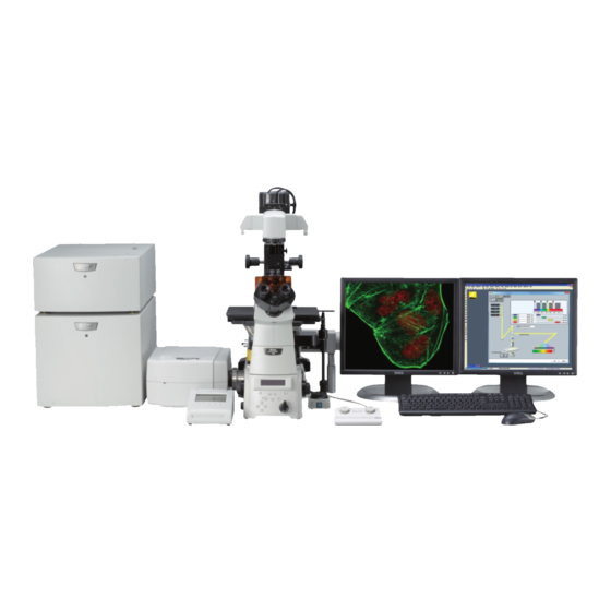
Title: Firefly Confocal (Nikon A1+) User Manual
Date of first issue:
23/10/2015
For assistance or to report an issue
Office: CG.07 or CG.05
Email:
Igmm-imaginghelpdesk@igmm.ed.ac.uk
Website:
www.igmm-imaging.com
Download a PDF copy of manual:
\\cmvm.datastore.ed.ac.uk\igmm\Imaging-Users\User
Manuals\Confocal\Firefly
Facility Usage Policy
1. You must have the relevant Risk Assessment/COSHH form for the
work you are undertaking before using imaging facility resources
2. Users must be trained before using facility equipment
3. Please leave the microscope clean and tidy for the next user
4. Please report any issue, even if it seems minor, to facility staff
5. Any clinical waste must be placed in the orange bins provided
Date of review:
28/08/2017
1
Version:
Admin
Advertisement
Table of Contents

Related Manuals for Nikon A1+


Summary of Contents for Nikon A1+
- Page 1 Title: Firefly Confocal (Nikon A1+) User Manual Date of first issue: Date of review: Version: 23/10/2015 28/08/2017 Admin For assistance or to report an issue Office: CG.07 or CG.05 Email: Igmm-imaginghelpdesk@igmm.ed.ac.uk Website: www.igmm-imaging.com Download a PDF copy of manual: \\cmvm.datastore.ed.ac.uk\igmm\Imaging-Users\User...
-
Page 2: Table Of Contents
Table of Contents System Startup ........................3 List of devices ........................4 System Shutdown ........................ 5 Mounting a sample ....................... 5 Finding the sample by eye ....................6 Nis-Elements software layouts ..................... 7 Selecting a confocal channel setup ..................7 Adding a brightfield channel .................... -
Page 3: System Startup
System Startup *See the next page for labelled images of all devices 1. Prior brightfield LED (only if required). Switched on via Prior Optiscan II box 2. Lasers-Turn the key on the front of the laser bed clockwise to the horizontal position (405/458/488/514/561 excitation lines) 3. -
Page 4: List Of Devices
List of devices... -
Page 5: System Shutdown
System Shutdown 1. Clean any oil immersion lenses used with the lens tissue 2. Close Nikon Nis-Elements 3. If the 640nm laser is turned on, maximise the 640 control software and select Off then close the window 4. Shutdown the PC Incubation chamber heater and CO2 supply if used 5. -
Page 6: Finding The Sample By Eye
Finding the sample by eye 1. Use the shortcut buttons (OC Panel) in Elements to select a wavelength to view. The “Eyes” heading indicates the relevant buttons. 2. Set the microscope focus to course movement using the button the right side of the microscope body. 3. -
Page 7: Nis-Elements Software Layouts
Nis-Elements software layouts 1. Nis-Elements has many toolbars which need to be changed depending on the experiment you are carrying out. The Layout tabs at the bottom left side of the screen allow you to change the software layout which essentially changes the toolbars visible too you. -
Page 8: Adding A Brightfield Channel
Adding a brightfield channel 1. Press the Channel Settings button in the A1Plus Compact GUI window 2. Press the Transmitted Detector “In” button to add a Brightfield channel 3. Select Ok to confirm 4. You will see that a TD detector has appeared in the list of channels and signifies that a brightfield image will be scanned 5. -
Page 9: Pre-Scan Acquisition Settings
Pre-scan acquisition settings *Consult the labelled diagram of the A1Plus Compact GUI (page 10) if you're not sure where any of the buttons mentioned below are 1. Before you can scan with the lasers you have to remove the laser interlock by pressing the red “Remove Interlock button”. -
Page 10: Optimising Scan Settings For Best Image Quality
Optimising scan settings for best image quality 1. Press the Scan button (lasers scan and the live image is constantly refreshed). Pressing Scan again will stop the scanning process. 2. The Find button can be used to increase the live image refresh rate by decreasing the size of the scanned area and the image quality. -
Page 12: Image Saturation
Image Saturation 1. As well as the image being too dark, it can also be too bright. The confocal acquires 12bit images. This means that any pixel in the image can have an intensity value between 0 (black)-4095 (white). The aim is to set the scan parameters so that the pixels are just below saturation level (4095). -
Page 13: Capture A Single Xy Image
Capture a single XY image Once the scan parameters have been optimised, press the Capture button to acquire a single scan of each active channel. Image Window Options 1. The captured image is displayed as a merge of all the channels by default. You can view individual channel images by selecting the channel tabs at the bottom of the image window. -
Page 14: Capture Images With Optical Zoom
Capture images with Optical Zoom 1. Optical zoom enables capture of a ROI within your image at higher magnification without the need to change the objective lens. Optical zoom can improve spatial resolution by changing the pixel size but can also increase photobleaching rates. 2. -
Page 15: Z Stack Acquisition
Z Stack Acquisition 1. To acquire a 3D dataset you need to define a Z stack acquisition 2. Enable only the Z Stack tick box within the ND Acquisition window 3. Choose the Z device from the dropdown box either Ti or MCL Nanodrive Piezo. -
Page 16: Z Stack Viewing Options
Z stack viewing options 1. You can view the different slices of the stack by left clicking with the mouse on the horizontal blue bars running along the bottom of the z stack image window 2. A z stack can be viewed in various ways. Pressing the Slices View button will display the XY and YZ orthogonal views as well as the standard XY view 3. -
Page 17: Xyzt Experiments
XYZT Experiments 1. Set up the scan settings as required 2. Enable both the Z and Time check boxes in the ND Acquisition window 3. Select the Time tab and tick the box under the Phase column. You can add multiple time phases which will run sequentially. -
Page 18: Multi-Position Xyzt Experiments
Multi-position XYZT Experiments 1. Enable the Z and Time options and set up these parameters as described above 2. Enable the XY check box in the ND Acquisition window 3. Here you can add multiple stage positions. Move to the position of interest and select the check box under the Point Name column 4. -
Page 19: Tile-Scan Experiments
Tile-Scan Experiments Basic Tiling 1. Enable the Large Image tick box in the ND Acquisition panel 2. Choose whether the tiled area is defined by the number of consecutive fields of view or by absolute area (mm x mm) 3. Enable the Stitch option if you want the output image to be the montage of all the tiles joined together 4. - Page 20 7. You can alter the number of fields of view to be scanned in the Area section and the number of fields of view on the macro image is automatically updated. 8. The Fields Placement option determines whether the tiling is around the current stage position or if the current position is the top left corner of entire tile scan.
-
Page 21: Frap/Bleaching Experiments
FRAP/Bleaching Experiments 1. This section of the manual describes how to enable and use the bleaching features of the confocal and only serves as a reference if you have already been trained to perform FRAP experiments by facility staff 2. Select the FRAP-FRET layout from the bottom left corner of the screen. This will show you additional toolbars required to carry out a FRAP experiment 3. - Page 22 can occur if too much light hits the detector. 12. To select a laser line for bleaching press the wavelength button i.e. 405 then set % power you would like to bleach with. Multiple lasers can be used for bleaching simultaneously if required.
- Page 23 24. Note that each ROI now has a label that denotes its function, S1, R2 and B3 25. Now that a Stimulation ROI has been defined, the Apply Stimulation Settings button is available in the ND Stimulation menu. When this button is pressed the Run Now button becomes available.
-
Page 24: Appendix
Appendix Saving Images Select the image window to save then select File>Save As from the top menu. Enter a file name and select ND2 as the file format. Export images in tiff format 1. Open the Image to be exported then select File>Import/Export>ND export to tiff... 2. -
Page 25: Kohler Illumination
Keep image as multchannel- Results in a multiplane tiff file where each frame of the stack is a channel and displayed in grey scale. The image contains the raw data if the keep bit depth option has also been selected Kohler Illumination 1. -
Page 26: Perfect Focus System (Pfs) Operation
Perfect Focus System (PFS) Operation PFS provides real time focus correction on a plane of interest during time lapse experiments carried out above room temperature. PFS is required because the microscope components expand as they heat which can cause the focus to drift. The coverslip/medium interface is tracked and the distance from the interface to the plane of focus is recorded as an offset value. -
Page 27: Frequently Asked Questions
Frequently Asked Questions 1. My images look noisy, what can I do to improve image quality? 1. Noise in an image comes from various sources but becomes more obvious when the sample signal is very low and you have to set a high gain value on the detector. Averaging captures multiple images of each channel but only displays the average of the total number captured. -
Page 28: I Can't Fit All Of The Tissue Into The Field Of View
3. I can't fit all of the tissue into the field of view 1. You can scan an area that is bigger than the field of view at the current magnification either by switching to a lower magnification lens or if you want to maintain the resolution you can perform a tiling experiment.