
Related Manuals for Metrologic MS9524


Summary of Contents for Metrologic MS9524
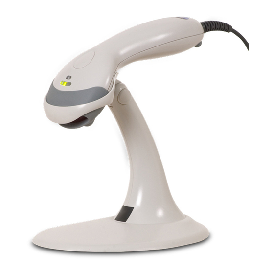
- Page 1 METROLOGIC INSTRUMENTS, INC. MS9524/44 Voyager Series ® Single-Line Hand Held Laser Scanner Installation and User’s Guide...
- Page 2 Copyright © 2006 by Metrologic Instruments, Inc. All rights reserved. No part of this work may be reproduced, transmitted, or stored in any form or by any means without prior written consent, except by reviewer, who may quote brief passages in a review, or provided for in the Copyright Act of 1976.
-
Page 3: Table Of Contents
ABLE OF ONTENTS Introduction......................1 Scanner and Accessories..................2 Installing the Scanner to the Host System RS232, Laser Emulation, and Light Pen ............4 IBM 46xx and OCIA..................5 Keyboard Wedge....................6 Stand-Alone Keyboard ..................7 Integrated USB Full Speed ....................8 Low Speed .................... - Page 4 ABLE OF ONTENTS Upgrading the Flash ROM Firmware ..............23 Labels......................... 24 Maintenance....................... 24 Depth of Field Minimum Bar Code Element Width ..............25 PDF417 Minimum Bar Code Element Width ..........26 IR Activation ....................... 27 Applications and Protocols ................. 28 Troubleshooting Guide ..................
-
Page 5: Introduction
® There are two models available, the MS9524 and the MS9544 with CodeGate The MS9524 is packed with all of the same features as the MS9544, with the exception of CodeGate. The MS9544 includes Metrologic’s patented auto trigger and CodeGate button feature. -
Page 6: Scanner And Accessories
53-53020x-3 2.7 m (9 ft.) coiled cord, long strain relief, black Other items may be ordered for the specific protocol being used. To order additional items, contact the dealer, distributor or call Metrologic’s Customer Service Department at 1-800-ID-METRO or 1-800-436-3876. - Page 7 Hard Mount Accessory Kit (used with kit #46-46128) 46-46433 Wall Mount Hanger Accessory Kit 46-46508 Other items may be ordered for the specific protocol being used. To order additional items, contact the dealer, distributor or call Metrologic’s Customer Service Department at 1-800-ID-METRO or 1-800-436-3876.
-
Page 8: Installing The Scanner To The Host System
The scanner and host system must use the same communication protocols. All MS9524-00/MS9544-00 scanners leave the factory with the Laser Emulation Mode enabled. If you recall defaults while re-configuring the scanner the Laser Emulation Mode will no longer be enabled. Refer to... -
Page 9: Ibm 46Xx And Ocia
NSTALLING THE CANNER TO THE YSTEM IBM 46xx and OCIA (MS9524-11/9 and MS9544-11/9) Turn off the host system. Plug the male 10-pin RJ45 end of the MVC cable into the 10-pin socket on the scanner. You will hear a ‘click’ when the connection is made. -
Page 10: Keyboard Wedge
NSTALLING THE CANNER TO THE YSTEM Keyboard Wedge (MS9524-47 and MS9544-47) Turn off the PC. Connect the 10-pin RJ45 male connector into the jack on the Voyager . You will hear a ‘click’ when the connection is made. Connect the L-shaped plug of the power supply into the power jack on the PowerLink cable. -
Page 11: Stand-Alone Keyboard
NSTALLING THE CANNER TO THE YSTEM Stand-Alone Keyboard (MS9524-47 or MS9544-47) Turn off the host system. Connect the 10-pin RJ45 male connector into the jack on the Voyager . You will hear a ‘click’ when the connection is made. Connect the L-shaped plug of the power supply into the power jack on the PowerLink cable. -
Page 12: Integrated Usb
USB port. Turn on the host system. Figure 5 As a default, the MS9524-38/MS9544-38 leaves the factory with USB Keyboard Emulation Mode enabled. For information on configuring the MS9524-38/MS9544-38 for USB Serial Emulation Mode, please refer to the USB section of the MetroSelect Single-Line Configuration Guide ( 00-02544). -
Page 13: The Powerlink Cable
OWER ABLE Disconnecting Before removing the cable from the scanner, Metrologic recommends that the power on the host system is off and the power supply has been disconnected from the PowerLink cable. Figure 6 Locate the small ‘pin-hole’ on the top of the unit near the bottom of the Voyager logo. -
Page 14: How To Scan
OW TO Three Modes of Operation Auto Trigger, In-Stand • Auto-triggers while in the stand • Bar code is automatically decoded and transmitted CodeGate, Out-of-Stand • CodeGate activates when removed from the stand • Bar code data is transmitted when the button is pressed Manual Activation Mode*, Out-of-Stand •... -
Page 15: How To Scan Pdf Bar Codes
OW TO Operator Note: PDF-CodeGate is disabled (by default) in all MS9544 Voyager units. The auto trigger activates the laser when the bar code is placed in the scanner's IR range. Figure 11. Laser Beam Position the laser line at the top of the code then sweep the beam over and down to the base of the code. -
Page 16: Stand
TAND Free Standing Kits #46-46128 a. Stand ( 36-00454)......Qty 1 MLPN b. Apron ( 50-50440)......Qty 1 MLPN c. Screw, M3 x 6 mm ( 18-18670) ..Qty 2 MLPN d. Washer, #5 x .5 OD ( 18-18671) ..Qty 2 MLPN e. Stand Anchor ( 50-50449) ....Qty 1 MLPN f. - Page 17 TAND There are two options for assembling the stand. The first option allows the stand to be self-supporting and moved freely or placed anywhere on the countertop. The second option is used if the stand will be bolted/hard-mounted to the countertop.
-
Page 18: Assembly
TAND Stand Option 2: Hard-mounted to countertop (continued) For use with kits #46-46128, #46-46351 and MS951 Stand Replacements Anchor from Step 3 Kit #46-46128 Screw the stand anchor ( 50-50449) MLPN Base Assembly from onto the base assembly until it sits flush. Kit #46-46351 or MS951 Stand Base Figure 21. - Page 19 TAND Wall Mount, Option 1: For Kit #46-46433 or Kit #46-46508 Step 1: Drill two #39 pilot holes 3.00” apart. Step 2: Attach the Wall Mount Hanger to the wall with the two #8 wood screws provided. Figure 26. Wall Mount, Option 2: Kit #46-46508 Step 1: Attach the Wall Mount Base to the Wall...
-
Page 20: Scanner Parts
CANNER ARTS Item Description White LED, see page 18 Yellow LED, available on the MS9544 only (see page 18). CodeGate Button, available on the MS9544 only (see page 10). Blue LED, see page 18 Output Window, Laser Aperture Cable Connection, see page 40 for connector pinouts Figure 29. -
Page 21: Indicators
NDICATORS Audible When the Voyager is in operation, it provides audible feedback. These sounds indicate the status of the scanner. Eight settings are available for the tone of the beep (normal, 6 alternate tones and no tone). To change the tone, refer to MetroSelect Single-Line Guide, 00-02544 or MetroSet2’s help files. -
Page 22: Visual
The MS9544 has three LED indicators (blue, white and yellow) located on the head of the scanner. The MS9524 has two LED indicators (blue and white) located on the head of the scanner. When the scanner is on, the flashing or stationary activity of the LEDs indicates the status of the current scan and the scanner. -
Page 23: Failure Modes
NDICATORS Visual Alternating Flashing of Blue and White This indicates the scanner is configuration mode. A razzberry tone indicates that an invalid bar code has been scanned while in this mode. The scanner needs to have a Flash ROM upgrade if the alternating flashing of the white and blue LEDs occurs during startup and is accompanied by three beeps. -
Page 24: Configuration Modes
• Bar Codes Voyager or Voyager with CodeGate can be configured by scanning the bar codes located in Metrologic's configuration guides, 00-02544 MLPN 00-02990 or MetroSet2’s help files. Please refer to these guides MLPN for instructions. These manuals can be downloaded for FREE from Metrologic’s website (www.metrologic.com). - Page 25 ONFIGURATION ODES During configuration, the motor and laser turn off. YOU CANNOT SCAN A BAR CODE WHILE IN SERIAL CONFIGURATION MODE. There is a 20 second window between commands. If a 20-second timeout occurs, the scanner will send a [nak] and you must start over. To enter serial configuration mode, send the following command [stx]999999[etx].
-
Page 26: Abbreviated Ascii Table
ONFIGURATION ODES EXAMPLE #3: The following example shows the events that occur when an invalid bar code is sent. This sample will load the factory default settings and then set the baud rate to 19200. ASCII REPRESENTATION SCANNER FEATURE HOST COMMAND RESPONSE RESPONSE Enter Configuration Mode... -
Page 27: Upgrading The Flash Rom Firmware
LASH IRMWARE The MetroSet2 program is a functional component of Metrologic’s new line of Flash-based scanners. This program allows the user of a Metrologic scanner to quickly upgrade to a new or custom version of software. It requires the use of a personal computer running under Windows 95 or greater and the use of a communication port. -
Page 28: Labels
ABELS Every scanner has labels and molded text located on the underside of the unit. The labels and text contain important information such as the unit’s date of manufacture, serial number, CE and caution information. Figure 30 provides examples of the labels and the molded text. Figure 30 AINTENANCE The output window will need occasional cleaning to prevent smudges and dirt... -
Page 29: Depth Of Field
EPTH OF IELD INIMUM LEMENT IDTH mils Figure 31. Specifications subject to change without notice. -
Page 30: Pdf417 Minimum Bar Code Element Width
EPTH OF IELD PDF417 M INIMUM LEMENT IDTH mils Figure 32. Specifications subject to change without notice. -
Page 31: Ir Activation
IR A CTIVATION Figure 33. Specifications subject to change without notice. -
Page 32: Applications And Protocols
* PDF bar codes are transmitted as Code 39 for these interfaces. Acceptance on host side is dependent on the host's ability to handle large amounts of data. The MS9524/44 Series Hand-Held Laser Scanner with built-in PC Keyboard Wedge Interface is designed for Keyboard emulation use only. Many RS232 configurable functions available in other Metrologic scanners are also available as keyboard wedge functions. -
Page 33: Troubleshooting Guide
ROUBLESHOOTING UIDE The following guide is for reference purposes only. Contact a Metrologic representative at 1-800-ID-Metro or 1-800-436-3876 to preserve the limited warranty terms. All Interfaces MS9524/44 Series Troubleshooting Guide Symptoms Possible Causes Solution Check the transformer, power outlet and power strip. - Page 34 ROUBLESHOOTING UIDE Symptoms Possible Causes Solution The unit scans a The unit is configured If the unit is setup to support bar code, but locks to support some form ACK/NAK, RTS/CTS, XON/XOFF up after the first of host handshaking, or D/E, verify that the host cable scan and the white but is not receiving and host are supporting the...
- Page 35 ROUBLESHOOTING UIDE Symptoms Possible Causes Solution Enable Caps Lock detect Alpha characters The computer is in setting of the scanner to detect show as lower Caps Lock mode. if the PC is operating in Caps case. Lock. Everything works These characters Try operating the scanner in Alt except for a may not be supported...
-
Page 36: Rs232 Demonstration Program
ROUBLESHOOTING UIDE RS232 Demonstration Program If an RS232 scanner is not communicating with your IBM compatible PC, key in the following BASIC program to test that the communication port and scanner are working. This program is for demonstration purposes only. It is only intended to prove that cabling is correct, the com port is working, and the scanner is working. - Page 37 Short Range: 0 mm – 100 mm ± 25 mm (0” – 4” ± 1”) Autodiscriminates all standard 1-D bar codes, RSS-14, PDF417 and truncated PDF417; for others symbologies call Decode Capability: a Metrologic service representative PC Keyboard Wedge, RS232, OCIA, Light Pen Emulation, System Interfaces: Laser Emulation, IBM 468X/469X, Stand-Alone Keyboard,...
- Page 38 ESIGN PECIFICATIONS ESIGN PECIFICATIONS LECTRICAL Input Voltage: 5.0VDC ± 0.25V Operating = 900 mW (typical) Power: Standby = 325 mW (typical) Operating = 250 mA @ 5VDC (typical) Current: Standby = 100 mA @ 5VDC (typical) DC Transformers: Class 2; 5.2VDC @ 650 mA IEC 60825-1:1993+A1:1997+A2:2001 Laser Class 1: EN 60825-1:1994+A11:1996+A2:2001...
-
Page 39: Default Settings
EFAULT ETTINGS Many functions of the scanner can be configured or enabled/disabled. The scanner is shipped from the factory configured to a set of default conditions. All default parameters of the scanner have an asterisk ( ) marked in the default column. - Page 40 EFAULT ETTINGS LIGHT LASER PARAMETER DEFAULT OCIA RS232 KBW USB 46XX EMULATION PDF CodeGate Inactive Out-of-Stand PDF CodeGate Active In-Stand PDF CodeGate Inactive In-Stand Mod 43 Check on Code 39 MSI-Plessy 10/10 Check Digit MSI-Plessy Mod 10 Check Digit Paraf Support ITF ITF Symbol Lengths Variable Minimum Symbol Length...
- Page 41 EFAULT ETTINGS LIGHT LASER PARAMETER DEFAULT OCIA RS232 KBW USB 46XX EMULATION Same symbol rescan timeout 250 msecs Same symbol rescan timeout 375 msecs Same symbol rescan timeout: 500 msecs) Same symbol rescan timeout 625 msecs Same symbol rescan timeout 750 msecs Same symbol rescan timeout 875 msecs...
- Page 42 EFAULT ETTINGS LIGHT LASER PARAMETER DEFAULT OCIA RS232 KBW USB 46XX EMULATION Parity Space Baud Rate 9600 8 Data Bits 7 Data Bits Stop Bits Transmit Sanyo ID Characters Nixdorf ID LRC Enabled UPC Prefix UPC Suffix Carriage Return Line Feed-Disabled by default in KBW Tab Prefix Tab Suffix...
- Page 43 EFAULT ETTINGS LIGHT LASER PARAMETER DEFAULT OCIA RS232 KBW USB 46XX EMULATION Bookland code 39 code 39 977 (2 digit) Supplemental Requirement Supplements are not Required Two Digit Redundancy Five digit Redundancy 100 msec to Find Supplement Configurable in 100 msec steps (max 800 msec) Coupon Code 128 code 39...
-
Page 44: Scanner And Cable Terminations
CANNER AND ABLE ERMINATIONS Scanner Pinout Connections MS9524/44-41 RS232C and Light Pen Emulation The MS9524 and MS9544 Function scanner interfaces terminate to a 10-pin modular jack. The Ground serial # label indicates the RS232 Transmit Output interface enabled when the... - Page 45 RS232 Receive Input Flip Sense/Start of Scan Output Proximity Detect/Trigger Emulation Output Scan/Laser Enable Input Reserved Data Out +5VDC Shield Ground MS9524/44-40 Full Speed USB MS9524/44-14 RS232 MS9524/44-38 Low Speed USB Function Function Ground Ground RS232 Transmit Output RS232 Transmit Output...
-
Page 46: Cable Connector Configurations
CANNER AND ABLE ERMINATIONS Cable Connector Configurations (Host End) RS232 PowerLink Cable 53-53000x-3 MLPN Function Shield Ground RS232 Transmit Output RS232 Receive Input DTR Input/Light Pen Source Power/Signal Ground Light Pen Data 9-Pin D-Type Connector (DSR Out for -14 interfaces) CTS Input RTS Output +5VDC... - Page 47 PC Clock No Connect Metrologic will supply an adapter cable with a 5-pin DIN male connector on one end and a 6-pin mini DIN female connector on the other. According to the termination required, connect the appropriate end of the adapter cable to the PowerLink cable, leaving the necessary termination exposed for connecting to the keyboard and the keyboard port on the PC.
-
Page 48: Limited Warranty
ARRANTY The MS9524/44 series scanners are manufactured by Metrologic at its Blackwood, New Jersey, USA facility. The MS9524/44 series scanners have a five (5) year limited warranty from the date of manufacture. Metrologic warrants and represents that all MS9524/44 series scanners are free of all defects in material, workmanship and design, and have been produced and labeled in compliance with all applicable US Federal, state and local laws, regulations and ordinances pertaining to their production and labeling. -
Page 49: Laser And Product Safety
ASER AND RODUCT AFETY EMC/EMI Notices The following is applicable when the scanner cable is not greater in length than 3 meters (9.8 feet) when fully extended. Les instructions ci-dessous s’appliquent aux cables de scanner ne dépassant pas 3 métres (9.8 pieds) de long en extension maximale. Warnung! Mit der streifenkodeabtaster kabel >3 meters voll ausgelastet sein. - Page 50 ASER AND RODUCT AFETY EMC/EMI Notices The following is applicable when the scanner cable is greater in length than 3 meters (9.8 feet) when fully extended. Les instructions ci-dessous s’appliquent aux cables de scanner dépassant 3 métres (9.8 pieds) de long en extension maximale. Warnung! Mit der streifenkodeabtaster kabel <3 meters voll ausgelastet sein.
-
Page 51: Cautions
ASER AND RODUCT AFETY Caution Caution Use of controls or adjustments or performance of procedures other than those specified herein may result in hazardous laser light exposure. Under no circumstances should the customer attempt to service the laser scanner. Never attempt to look at the laser beam, even if the scanner appears to be nonfunctional. -
Page 52: Patents
ATENTS Patent Information This METROLOGIC product may be covered by one or more of the following US Patents: US Patent No. 5,260,553; 5,340,971; 5,340,973; 5,424,525; 5,468,951; 5,484,992; 5,525,789; 5,528,024; 5,591,953; 5,616,908; 5,627,359; 5,661,292; 5,777,315; 5,789,730; 5,789,731; 5,811,780; 5,825,012; 5,828,048; 5,883,375;... -
Page 53: Index
NDEX interface ......33, 40–43 IBM 46xx ....5, 28, 35–39 AC ........see power Keyboard Wedge. 2, 6, 28, 35–39 accessories .......2, 3 Laser Emulation ..4, 28, 35–39 adapter ..........2 Light Pen ....4, 28, 35–39 aperture .........16, 24 OCIA .... - Page 54 NDEX safety........45–47 UL ..........24 SELV .........4–8 USB ......see interface software......see flash specification electrical........34 voltage ........2, 34 environmental ......34 mechanical.......33 operation........33 wall hook ....... 12, 15 speed ..........33 warranty ........ 29, 44 stand ..... 3, 10, 12–15, 35 white ......
- Page 56 May 2006 Printed in the USA 0 0 - 0 2 9 8 9 D...