Metrologic Voyager MS9500 Series Installation And User Manual
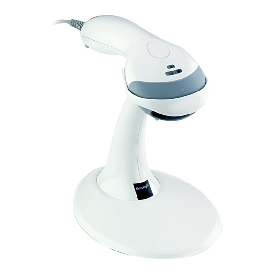
Single-line hand held laser scanner
Hide thumbs
Also See for Voyager MS9500 Series:
- Installation and user manual (56 pages) ,
- Product manual (6 pages) ,
- Specification sheet (2 pages)

Related Manuals for Metrologic Voyager MS9500 Series


Summary of Contents for Metrologic Voyager MS9500 Series
- Page 1 METROLOGIC INSTRUMENTS, INC. MS9500 Voyager Series ® Single-Line Hand Held Laser Scanner Installation and User's Guide...
- Page 2 Copyright © 2008 by Metrologic Instruments, Inc. All rights reserved. No part of this work may be reproduced, transmitted, or stored in any form or by any means without prior written consent, except by reviewer, who may quote brief passages in a review, or provided for in the Copyright Act of 1976.
-
Page 3: Table Of Contents
Scanner Components... 4 The PowerLink Cable Disconnecting... 5 Connecting ... 5 Labels... 6 Maintenance... 6 Installing the Scanner to the Host System RS232, Laser Emulation, and Light Pen Emulation... 7 RS485 ... 8 Keyboard Wedge... 9 Stand-Alone Keyboard ... 10 Integrated USB Full Speed ... - Page 4 Operational... 31 Mechanical ... 32 Electrical... 32 Environmental ... 32 Default Settings ... 33 Scanner and Cable Terminations Scanner Pinout Connections ... 38 Cable Connector Configurations ... 40 Limited Warranty ... 42 Regulatory Compliance Safety ... 43 EMC ... 44 Patents ...
-
Page 5: Product Overview
The MS9540, VoyagerCG incorporates Metrologic’s patented auto-trigger and CodeGate button feature. When a bar code is place in the scanner’s IR range, the auto-trigger activates the laser enabling the user to align the visible laser line over the bar code selected for scanning. The user can then press the CodeGate button, to transmit the data to the host system. -
Page 6: Scanner And Accessories
NTRODUCTION Scanner and Accessories Part # MS9520 Voyager Bar Code Scanner MS9540 VoyagerCG Bar Code Scanner with CodeGate 00-02544 MetroSelect Single-Line Configuration Guide* MS9500 Voyager Series Single-Line Hand Held Laser 00-02410 Scanner Installation and User’s Guide* Available for download on the Metrologic website - www.metrologic.com Part # AC to DC Power Transformer - Regulated 5.2VDC @ 1A output. - Page 7 NTRODUCTION Scanner and Accessories Part # USB Full Speed Cable Locking Plus-Power™ Type A, 53-53213x-N-3 Black, Coiled Cord with Long Strain Relief USB Full Speed Cable Locking Plus-Power™ Type A, Black, Coiled Cord with Long Strain Relief, Extended Length 53-53214x-N-3...
-
Page 8: Scanner Components
See Visual Indicators on page 18 See Visual Indicators on page 18 See How to use CodeGate on page 12 Laser Aperture See Audible Indicators on page 17 10-pin RJ45, Female Socket, See Scanner Pinout Connections on page 38 Figure 1. Scanner Components... -
Page 9: Disconnecting
NTRODUCTION Disconnecting the PowerLink Cable Before removing the cable from the scanner, Metrologic recommends that the power on the host system is off and the power supply has been disconnected from the PowerLink cable. Locate the small ‘pin-hole’ on the top of the unit near the bottom of the Voyager logo. -
Page 10: Labels
NTRODUCTION Labels Every scanner has labels and molded text located on the underside of the unit. The labels and text contain important information such as the unit’s date of manufacture, serial number, CE and caution information. Figure 5 provides examples of the labels and the molded text. -
Page 11: Installing The Scanner To The Host System
Turn on the host system. Plugging the scanner into a port on the host system does not guarantee that scanned information will be communicated properly to the host system. Please refer to the MetroSelect Single-Line Configuration Guide or MetroSet2’s help files for instructions on changing the... -
Page 12: Rs485
Turn on the host system. Plugging the scanner into a port on the host system does not guarantee that scanned information will be communicated properly to the host system. Please refer to the MetroSelect Single-Line Configuration Guide or MetroSet2’s help files for instructions on changing the... -
Page 13: Keyboard Wedge
DIN adapter). Power up the host system. Plugging the scanner into a port on the host system does not guarantee that scanned information will be communicated properly to the host system. Please refer to the MetroSelect Single-Line Configuration Guide or MetroSet2’s help files for instructions on changing the scanner’s factory default configuration. -
Page 14: Stand-Alone Keyboard
Contact a Metrologic Customer Service Representative if you require an external power supply. Plugging the scanner into a port on the host system does not guarantee that scanned information will be communicated properly to the host system. Please refer to the MetroSelect Single-Line Configuration Guide or MetroSet2’s help files... -
Page 15: Integrated Usb Full Speed
Emulation Mode, please refer to the USB section of the MetroSelect Single-Line Configuration Guide ( Plugging the scanner into a port on the host system does not guarantee that scanned information will be communicated properly to the host system. Please refer to the MetroSelect Single-Line Configuration Guide or MetroSet2’s help files for instructions on changing the... -
Page 16: The Ms9540 Voyagercg ® Series
MS9540 V OYAGER How to Use CodeGate and the Manual Activation Mode Figure 11. Three Modes of Operation Auto Trigger, In-Stand • Auto-triggers while in the stand • Bar code is automatically decoded and transmitted CodeGate, Out-of-Stand • CodeGate activates when removed from the stand •... -
Page 17: Stand Kits
TAND Types Free Standing Kit #46-46128 (Figure 13) Kit Contains: a. Stand... Qty. 1 b. Apron... Qty. 1 c. Screw, M3 x 6 mm ... Qty. 2 d. Washer, #5 x .5 OD... Qty. 2 e. Stand Anchor ... Qty. 1 Figure 13. -
Page 18: Assembly
TAND Assembly There are two options for assembling the stand. The first option is a self- supporting stand that can be moved freely about on the countertop. The second option is used if the stand will be bolted or hard-mounted to the countertop. Stand Option 1: Self-Supported Stand Kit #46-46128 Step 1 Slide the apron over the stand. - Page 19 TAND Assembly Stand Option 2: Hard-Mount Kits #46-46128 and #46-46351 Anchor from Kit #46-46128 Base Assembly from Kit #46-46351 or MS951 Stand Base Figure 21. Figure 22. Figure 23. Figure 24. Figure 25. Step 3 Screw the stand anchor onto the base assembly until it sits flush.
- Page 20 TAND Assembly Wall Mount, Option 1: For Kit #46-46508 Step 1 Drill two #39 pilot holes 3.00″ apart. Step 2 Attach the Wall Mount Hanger to the wall with the two #8 wood screws provided. Wall Mount, Option 2: Kit #46-46508 Step 1 Attach the Wall Mount Base to the Wall Mount Hanger with the two...
-
Page 21: Indicators
When the Voyager is in operation, it provides audible feedback. These sounds indicate the status of the scanner. Eight settings are available for the tone of the beep (normal, 6 alternate tones and no tone). To change the beeper tone, refer to the MetroSelect Single-Line Configuration Guide or MetroSet2’s help files. -
Page 22: Visual
The scanner is in stand-by mode, and CodeGate is enabled. Present a bar code to the scanner and the green LED will turn on when the laser turns on. Steady Yellow (MS9540’s Only) The CodeGate button is not active. If a bar code is in the scan field, the laser will turn on. -
Page 23: Failure Modes
Continuous Razzberry Tone with all LEDs Off If, upon power, the scanner emits a continuous razzberry tone, then the scanner has an experienced an electronic failure. Return the unit for repair to an authorized service center. Three Beeps – on power up If the scanner beeps three times on power up then the non-volatile memory (NovRAM) that holds the scanner configuration has failed. -
Page 24: Configuration Modes
String Sent to Scanner = 02h 31h 30h 30h 31h 30h 34h 03h (All values are hexadecimal). If the command sent to the scanner is valid, the scanner will respond with an [ack]. If the command sent to the scanner in invalid, the scanner will respond with a [nak]. - Page 25 This mode uses the current Baud Rate, Parity, Stop Bits and Data Bits settings that are configured in the scanner. The default settings of the scanner are 9600, Space, 2, 7 respectively. If a command is sent to the scanner to change any of these settings, the change will NOT take effect until after serial configuration mode is exited.
-
Page 26: Abbreviated Ascii Table
The scanner will beep three times! This example illustrates two important points. First, if an invalid command is sent from the host, the scanner responds with a [nak] and the end-user must start over from the beginning. Second, if a command is sent to change the Baud Rate, the new baud rate does not take effect until after the end-user exits configuration mode. -
Page 27: Upgrading The Firmware
Click on the Open File button in the Flash Utility window. Locate and open the flash upgrade file supplied by Metrologic. Select the COM port that the scanner is connected to on the host system. 10. Verify the settings listed in the Flash Utility window. -
Page 28: Depth Of Field
EPTH OF IELD mils INIMUM LEMENT Figure 30. Depth of Field IDTH... -
Page 29: Ir Activation Range
CTIVATION ANGE The scanner's laser will turn off if the scanner has been idle. When the scanner's IR detects movement in the activation area (see figure below), the laser will automatically turn on, preparing the scanner for bar code recognition, decoding, and transmission. -
Page 30: Applications And Protocols
PPLICATIONS AND The model number on each scanner includes the scanner number and factory default communication protocol. Scanner Version Identifier MS9520 MS9540 ® Applicable for IBM The MS9520/9540 Keyboard Wedge Series (-47) is designed for keyboard emulation only. Many RS232 configurable functions available in other Metrologic scanners are also available as keyboard wedge functions. -
Page 31: Troubleshooting Guide
ROUBLESHOOTING The following guide is for reference purposes only. Contact a Metrologic representative at 1-800-ID-Metro or 1-800-436-3876 to preserve the limited warranty terms. Symptoms All Interfaces The unit has no LEDs, beep or laser. No power is being At power up the unit beeps 2 times and alternately flashes the LEDs. - Page 32 Check if the correct minimum symbol length is set. Make sure the scanner is configured for the appropriate mode. Check that the scanner and the host are configured for the same interface parameters. Add some inter-character delay to the transmitted output by using the MetroSelect Single-Line Configuration Guide.
- Page 33 It may be necessary to try this in both settings. Enable the Caps Lock detect feature of the scanner to detect whether the PC is operating in Caps Lock. Try operating the scanner in Alt mode. Check to make sure that the baud...
-
Page 34: Rs232 Demonstration Program
RS232 D EMONSTRATION If an RS232 scanner is not communicating with an IBM compatible PC, key in the following BASIC program to test that the communication port and scanner are working. This program is for demonstration purposes only. It is only intended to prove that cabling is correct, the COM port is working, and the scanner is working. -
Page 35: Design Specifications
ESIGN PECIFICATIONS PERATIONAL Light Source Laser Power: Depth of Scan Field: Scan Speed: Scan Pattern: Minimum Bar Width: Infrared Activation: Decode Capability: System Interfaces: Print Contrast: Number Characters Read: Roll, Pitch, Yaw: Beeper Operation: Visual Indicators: Default Settings In some custom units, the standard green LED has been replaced with a blue LED and the red LED has been replaced with a white LED. -
Page 36: Mechanical
ESIGN PECIFICATIONS ECHANICAL Length: Width: Depth: Weight: LECTRICAL Input Voltage: Power: Current: DC Transformers: For regulatory compliance information see pages 43 – 45. NVIRONMENTAL Temperature: Humidity: Light Levels: Shock: Contaminants: Ventilation: Specifications are subject to change without notice. MS9500 Series Specifications 198 mm (7.8") Handle - 45 mm (1.8"), Head - 78 mm (3.1") 40 mm (1.6") -
Page 37: Default Settings
The scanner is shipped from the factory configured to a set of default conditions. All default parameters of the scanner have an asterisk ( * ) marked in the default column. If an asterisk is not in the default column then the default setting is off or disabled. - Page 38 EFAULT ETTINGS Parameter Mod 43 Check on Code 39 MSI-Plessy 10/10 Check Digit MSI-Plessy Mod 10 Check Digit Paraf Support ITF ITF Symbol Lengths Minimum Symbol Length Symbol Length Lock Bars High as Code 39 Spaces High as Code 39 Bars High as Scanned Spaces High as Scanned DTS/SIEMENS...
- Page 39 EFAULT ETTINGS Parameter Same symbol rescan timeout: 750 msecs Same symbol rescan timeout: 875 msecs Same symbol rescan timeout: 1000 msecs No Same symbol timeout Infinite Same symbol timeout Inter-character delay Configurable in 1 msec steps (max 255 msecs) Number of scan buffers (maximum) Transmit UPC-A check digit Transmit UPC-E check digit...
- Page 40 EFAULT ETTINGS Parameter Transmit Sanyo ID Characters Nixdorf ID LRC Enabled UPC Prefix UPC Suffix Carriage Return Line Feed-Disabled by default in KBW Tab Prefix Tab Suffix “DE” Disable Command “FL” Laser Enable Command DTR Handshaking support RTS/CTS Handshaking Character Message RTS/CTS XON/XOFF Handshaking ACK/NAK...
- Page 41 EFAULT ETTINGS Parameter 100 msec to Find Supplement Configurable in 100 msec steps (max 800 msec) Coupon Code 128 † Configurable Code Lengths † Code Selects with configurable Code Length Locks Configurable Prefix characters Suffix characters Prefixes for Individual Code types Editing Inter Scan-Code delay configurable...
-
Page 42: Scanner And Cable Terminations
Scanner Pinout Connections The MS9520 and MS9540 scanner interfaces terminate to a 10-pin modular jack. The serial # label indicates the interface enabled when the scanner is shipped from the factory. ® Applicable for IBM host applications. ERMINATIONS RS232 and Light Pen Emulation... - Page 43 CANNER AND ABLE Scanner Pinout Connections Ground RS232 Transmit Output RS232 Receive Input Flip Sense/Start of Scan Output Proximity Detect/Trigger Emulation Output Scan/Laser Enable Input Reserved Data Out +5VDC Shield Ground MS95x0-14 RS232 Function Ground RS232 Transmit Output RS232 Receive Input...
-
Page 44: Cable Connector Configurations
CANNER AND ABLE Cable Connector Configuration (Host End) RS232 PowerLink Cable 53-53000x-3 MLPN Function Shield Ground RS232 Transmit Output RS232 Receive Input DTR Input/Light Pen Source Signal Ground Light Pen Data (DSR Out for -14 interfaces) CTS Input RTS Output +5VDC USB Cables 53-53213x-N-3, 53-53214x-N-3... - Page 45 CANNER AND ABLE Cable Connector Configuration (Host End) Keyboard Wedge PowerLink Cable 53-53002x-3 MLPN Function Keyboard Clock Keyboard Data No Connect Power Ground +5 Volts DC Function PC Data No Connect Power Ground +5 Volts DC PC Clock No Connect Metrologic will supply an adapter cable with a 5-pin DIN male connector on one end and a 6-pin mini DIN female connector on the other.
-
Page 46: Limited Warranty
SHALL ANY LIABILITY OF METROLOGIC EXCEED THE ACTUAL AMOUNT PAID TO METROLOGIC FOR THE PRODUCT. METROLOGIC RESERVES THE RIGHT TO MAKE ANY CHANGES TO THE PRODUCT DESCRIBED HEREIN. ORPORATE EADQUARTERS ORTH MERICA Metrologic Instruments, Inc. 90 Coles Rd. Blackwood, NJ 08012-4683 Customer Service Department Tel: 1-800-ID-METRO Fax: 856-228-6673 Email: info@metrologic.com... -
Page 47: Regulatory Compliance Safety
Never attempt to look at the laser beam, even if the scanner appears to be nonfunctional. Never open the scanner in an attempt to look into the device. Doing so could result in hazardous laser light exposure. The use of optical instruments with the laser equipment will increase eye hazard. -
Page 48: Emc
Class A Devices The following is applicable when the scanner cable is greater in length than 3 meters (9.8 feet) when fully extended: Les instructions ci-dessous s’appliquent aux cables de scanner dépassant 3 métres (9.8 pieds) de long en extension maximale:... - Page 49 Class B Devices The following is applicable when the scanner cable is less than 3 meters (9.8 feet) in length when fully extended: Les instructions ci-dessous s’appliquent aux cables de scanner ne dépassant pas 3 métres (9.8 pieds) de long en extension maximale:...
-
Page 50: Patents
ATENTS This METROLOGIC product may be covered by, but not limited to, one or more of the following US Patents: US Patent No. 5,081,342; 5,260,553; 5,340,971; 5,340,973; 5,424,525; 5,468,951; 5,484,992; 5,525,789; 5,528,024; 5,591,953; 5,616,908; 5,627,359; 5,661,292; 5,777,315; 5,789,730; 5,789,731; 5,811,780; 5,825,012; 5,828,048; 5,883,375;... -
Page 51: Index
NDEX AC ... see power accessories ...2, 3 adapter ...2 cable... 2–3, 27–29 adapter ...2 communication ... 1, 2–3, 5, 7–11, 29, 33, 38–41 disconnect ...5 MVC...3, 8 pin assignments...38–41 caution...6, 43 labels ...6 laser...6 CE ...see caution CodeGate ... 1, 12, 18, 33 communication ...27–29 compliance ...43–45 configuration.. - Page 52 NDEX parameter ...33–37 pin assignments ... see cable power ... 2, 7–11, 27, 32 PowerLink...41, see cable protocols... see interface razzberry tone ...see indicator Red LED...see indicator regulatory compliance ...43–45 repair ...42 RMA ...42 RS232 ... see interface RS485 ... see interface safety...43 SELV ...see caution serial number...6...
- Page 55 April 2008 Printed in China 0 0 - 0 2 4 1 0 K...
- Page 56 January 2008, Version 03 Printed in the USA 0 0 - 0 2 4 1 0 J...