
Related Manuals for Metrologic MS9535


Summary of Contents for Metrologic MS9535
- Page 1 METROLOGIC INSTRUMENTS, INC. MS9535 Voyager BT™ Wireless Hand-Held Laser Scanner Installation and User’s Guide...
- Page 3 Copyright © 2005 by Metrologic Instruments, Inc. All rights reserved. No part of this work may be reproduced, transmitted, or stored in any form or by any means without prior written consent, except by reviewer, who may quote brief passages in a review, or provided for in the Copyright Act of 1976.
-
Page 4: Table Of Contents
USB Keyboard Scanner Installation ... 7 IBM Scanner Installation... 8 Full Speed USB with External Power Supply Scanner Installation ... 9 Full Speed USB with Power From Register Scanner Installation ... 10 Establish Communication Between Scanner and Cradle ... 11 Charging the Scanner ... -
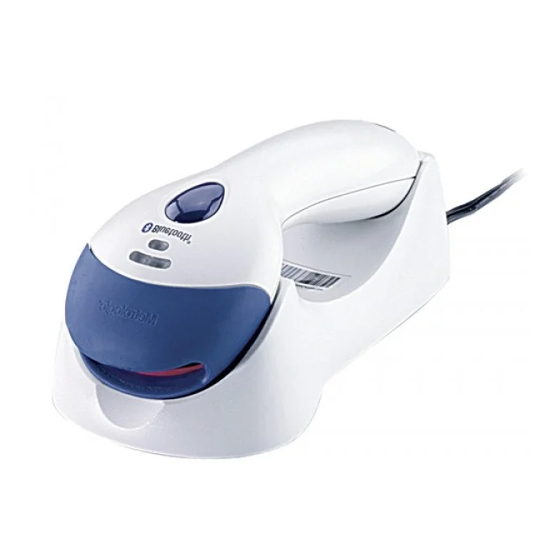
Page 5: Introduction
The cradle of the Voyager When resting in the cradle, the scanner can reach a fully charged state in 2.5 hours. When fully charged, the scanner can provide up to 12,000 scans. For power saving, the scanner can be put into a full sleep mode by depressing the CodeGate button for 5 seconds after the laser has shut down. -
Page 6: Scanner And Accessories
CANNER AND CCESSORIES Part # 9535-5 Voyager 9535-5M Voyager MS9535 VoyagerBT Wireless Hand Held Laser Scanner 70-79004 Installation and User’s Guide* 00-02544 MetroSelect Single-Line Programming Guide* 00-02024 Bluetooth Programming Addendum 70-73524 Wrist Strap Available on the Metrologic website - www.metrologic.com... -
Page 7: Quick Start
Connect the power supply into an AC outlet. The blue LED on the rear of the cradle will stay on. Pick up the scanner and scan the Bluetooth address code on the cradle; you will hear 3 continuous beeps. After 4 seconds, both the blue LEDs of the charger cradle and the scanner flashes, followed by 2 combination beeps. - Page 8 Auto-trigger mode When the scanner is at rest in the cradle, it is in auto-trigger mode. While in this mode, present a bar code in the scanning field and the data is automatically decoded and transmitted.
-
Page 9: Rs232 And Light Pen Scanner Installation
Caution: To maintain compliance with applicable standards, all circuits connected to the scanner must meet the requirements for SELV ( Safety Extra Low Voltage) according to EN 60950. To maintain compliance with standard CSA C22.2 No. 950/UL 1950 and norm EN 60950, the power source should meet applicable performance requirements for a limited power source. -
Page 10: Keyboard Wedge Scanner Installation
Power up the host system. Caution: To maintain compliance with applicable standards, all circuits connected to the scanner must meet the requirements for SELV ( Safety Extra Low Voltage) according to EN 60950. To maintain compliance with standard CSA C22.2 No. 950/UL 1950 and norm EN 60950, the power source should meet applicable performance requirements for a limited power source. -
Page 11: Usb Keyboard Scanner Installation
Turn on the host system. Caution: To maintain compliance with applicable standards, all circuits connected to the scanner must meet the requirements for SELV ( Safety Extra Low Voltage) according to EN 60950. To maintain compliance with standard CSA C22.2 No. 950/UL 1950 and norm EN 60950, the power source should meet applicable performance requirements for a limited power source. -
Page 12: Ibm Scanner Installation
Turn on the host system. Caution: To maintain compliance with applicable standards, all circuits connected to the scanner must meet the requirements for SELV ( Safety Extra Low Voltage) according to EN 60950. To maintain compliance with standard CSA C22.2 No. 950/UL 1950 and norm EN 60950, the... -
Page 13: Full Speed Usb With External Power Supply Scanner Installation
Turn on the host system. Caution: To maintain compliance with applicable standards, all circuits connected to the scanner must meet the requirements for SELV ( Safety Extra Low Voltage) according to EN 60950. To maintain compliance with standard CSA C22.2 No. 950/UL 1950 and norm EN 60950, the power source should meet applicable performance requirements for a limited power source. -
Page 14: Full Speed Usb With Power From Register Scanner Installation
Turn on the host system. Caution: To maintain compliance with applicable standards, all circuits connected to the scanner must meet the requirements for SELV ( Safety Extra Low Voltage) according to EN 60950. To maintain compliance with standard CSA C22.2 No. 950/UL 1950 and norm EN 60950, the power source should meet applicable performance requirements for a limited power source. -
Page 15: Establish Communication Between Scanner And Cradle
Each scanner will only communicate with the last cradle address scanned. Once a cradle is paired with a scanner, another scanner can not be paired with that cradle until the connection is broken. The connection can be easily broken by placing the unit into sleep mode by holding down the CodeGate button for three (3) seconds. -
Page 16: Charging The Scanner
LED turns steady. Manufacturer’s Suggestion: If the scanner is not be used for a long period of time, it is suggested that the unit be placed into normal or full sleep mode to save power. For normal sleep mode, scan the configuration bar codes in the Bluetooth Programming Addendum (00- 02024A). - Page 17 HARGING THE CANNER Safety Precautions for Lithium Batteries: • Do not place batteries in fire or heat the batteries • Do not store batteries near fire or other high temperature locations • Do not store or carry batteries together with metal objects •...
-
Page 18: Receiver / Charger Cradle
ECEIVER HARGER The cradle of MS9535 works both as a receiver and a charger. As a receiver, after establishing Bluetooth communication with the scanner, the cradle receives date being scanned by the scanner and transmits it to the host. To communicate with different host interfaces, the cradle is offered in various configurations. -
Page 19: Cradle Parts
Page Button The page button is located at the rear of the cradle. When the scanner associated with the cradle can not be found, press the page button; the scanner will begin beeping and the blue and amber LEDs will flash alternatively. -
Page 20: Scanner Parts
CANNER ARTS Amber LED CodeGate Button White LED Blue LED MS9535 Top View MS9535 Top View Output Window Plastic Feet/ Charge Contacts MS9535 Side View... -
Page 21: Audible Indicators
When the scanner is in operation, it provides audible feedback. These sounds indicate the status of the scanner. Eight settings are available for the tone of the beeper (normal, 6 alternate tones and no tone). To change the tones, refer to the MetroSelect Single-Line Programming Guide ( help files. -
Page 22: Visual Indicators
ISUAL NDICATORS The MS9535 has three LED indicators (blue, white and amber) located on the head of the scanner. When the scanner is in operation, the flashing or stationary activity of the LEDs indicates the status of the current scan and the scanner. - Page 23 LEDs will occur during startup and is accompanied by three beeps. Steady White, Blue off This indicates the laser is off and the scanner is still waiting for communication from the cradle. Flashing Blue This indicates the scanner is trying to establish communication with the cradle.
-
Page 24: Failure Modes
Return the unit for repair to an authorized service center. Three Beeps – on power up If the scanner beeps 3 times on power up then the non- volatile memory (NovRAM) that holds the scanner configuration has failed. If the scanner does not respond after reprogramming, return the scanner for repair to an authorized service center. -
Page 25: Programming Modes
FREE from Metrologic’s website (www.metrologic.com). MetroSet2 This user-friendly Windows-based configuration program allows you to simply ‘point-and-click’ at the desired scanner options. This program can be downloaded for FREE from Metrologic’s website (www.metrologic.com), or set-up disks can be ordered by calling 1-800-ID-METRO. -
Page 26: Upgrading The Flash Rom Firmware
The user merely connects the scanner to a communications port of the PC, launches the MetroSet 2 program, and blasts off to new software upgrades. Each MS9535 and its cradle, regardless of the version number or communication protocol, can be upgraded. In other words, all RS232/Light Pen (-41), keyboard wedge (-47), USB (-38), FS USB (C40), FS USB (D40), and IBM 468X/469X (-11) units can be upgraded. -
Page 27: Labels
ABELS Each scanner has a label on the back of the unit. This label has the model number, date of manufacture, serial number, CE and caution information. The following is an example of this label: EVITER TOUTE EXPOSITION-Lumiere laser emis par cette overture AVOID EXPOSURE –Laser light is emitted from this aperture... -
Page 28: Depth Of Field
EPTH OF IELD mils Minimum Bar Code Element Width... -
Page 29: Ir Activation
IR A CTIVATION... -
Page 30: Connecting To Other Bluetooth Devices
A Bluetooth communication between the scanner and the other device must be established before the system works. When MS9535 acts as Client: The MS9535 is defaulted to act as client when connected to other Bluetooth devices. Communication is established by scanning the Bluetooth address code of the other device. - Page 31 ONTINUED When MS9535 acts as Server: To enable the MS9535 to act as a server and to be discovered by another Bluetooth device, scan the below Provide Service code. This will allow other Bluetooth devices to send inquiries to the scanner and attempt communication.
-
Page 32: Troubleshooting Guide
UIDE Check transformer, outlet and power strip. Make sure the cable is plugged into the cradle properly. Place the scanner into cradle to recharge the battery. Establish communication between scanner and cradle before scanning a normal bar code... - Page 33 (Typical of Non-UPC/EAN codes) The scanner defaults to a minimum of 3-character bar code. If the scanner is setup to support ACK/NAK, RTS/CTS, XON/XOFF or D/E, verify that the host cable and host are supporting the handshaking properly.
- Page 34 Make sure that the proper PC type AT, PS2 or XT is selected. Verify correct country code and data formatting are selected. Adjust inter-character delay symptom. Enable Caps Lock detect setting of the scanner to detect whether the PC is operating in Caps Lock. Solution...
- Page 35 Try operating the scanner in Alt mode. Check to make sure that the baud rate and parity of the scanner and the communication port match and the program is looking for “RS-232” data. Check to make sure that the baud...
-
Page 36: Design Specifications
40 mm (1.6”) Scanner: 199 g (7.02 oz) Scanner: 5.2VDC ± 0.25V Cradle: 5.2VDC ± 0.25V Scanner: Operating = 1.15 W, Sleep = 150 mW Cradle: 0.6 W Scanner:Operating=230 mA@5VDC, Sleep=30mA@ 5VDC Cradle: 120 mA @ 5VDC Class II; 5.2V @ 2A... -
Page 37: Default Settings
EFAULT ETTINGS Many functions of the scanner and cradle can be “programmed” – that is, enabled or disabled. The scanner and cradle are shipped from the factory programmed to a set of default conditions. The default parameter has an asterisk (*) in the charts on the following pages. If an asterisk is not in the default column then the default setting is OFF or DISABLED. - Page 38 EFAULT ETTINGS PARAMETER Mod 43 Check on Code 39 MSI-Plessey 10/10 Check Digit MSI-Plessey Mod 10 Check Digit Paraf Support ITF ITF Symbol Lengths Minimum Symbol Length Symbol Length Lock Bars High as Code 39 Spaces High as Code 39 Bars High as Scanned Spaces High as Scanned DTS/SIEMENS...
- Page 39 Code 39 Transit Mod 10/ITF Transmit MSI-Plessy Parity Baud Rate 8 Data Bits 7 Data Bits Stop Bits CONTINUED LIGHT DEFAULT RS-232 1 msecs 10 msecs in KBW Scanner: Space Cradle: None 9600 Scanner: * Cradle: * 46XX...
- Page 40 EFAULT ETTINGS PARAMETER Transmit Sanyo ID Characters Nixdorf ID LRC Enabled UPC Prefix UPC Suffix Carriage Return Line Feed-Disabled by default in KBW Tab Prefix Tab Suffix “DE” Disable Command “FL” Laser Enable Command DTR Handshaking support RTS/CTS Handshaking Character Message RTS/CTS XON/XOFF Handshaking ACK/NAK...
- Page 41 EFAULT ETTINGS PARAMETER 100 msec to Find Supplement Programmable in 100 msec steps (max 800 msec) Coupon Code 128 † Programmable Code Lengths † Code Selects with programmable Code Length Locks Programmable Prefix characters Suffix characters Prefixes for Individual Code types Editing Inter Scan-Code delay programmable...
-
Page 42: Cradle And Cable Terminations
RADLE AND ABLE Cradle Pinout Connections The MS9535 cradle has 3 ports on the bottom. One is for power, and the other two are for interfaces connection.The 10-pin RJ45 modular jack has diffent configurations for different interfaces. 10-Pin RJ45 MI9535-547... - Page 43 RADLE AND ABLE MI9535-511 Function Ground RS-232 Transmit Output RS-232 Receive Input RTS Output CTS Input DTR Input IBM B- Transmit IBM A+ Receive Reserved ERMINATIONS CONTINUED MI9535C540 / MI9535D540 Full Speed USB Function Ground RS-232 Transmit Output RS-232 Receive Input RTS Output CTS Input USB +5V...
- Page 44 RADLE AND ABLE USB Port Ground Cable Connector Configurations (Host End) RS232/Light Pen Cable [ 9-pin D-type female connector to the PC Function Shield Ground RS-232 Transmit Output RS-232 Receive Input DTR Input/Light Pen Source Power/Signal Ground Light Pen Data CTS Input RTS Output +5VDC...
- Page 45 RADLE AND ABLE Cable [ MLPN Function Ground IBM A+ IBM B- Reserved Full Speed USB Cable with power from Register 54-54073A] MLPN Function +5VDC Ground Ground +12V +12V Ground Full Speed USB Cable with external Power Supply 54-54200A-N] MLPN Function +5VDC Ground...
-
Page 46: Cable Connector Configurations
RADLE AND ABLE Cable Connector Configuration The Keyboard Wedge cable [ female connector on one end, and a 6-pin mini DIN male on the other. Keyboard Wedge Cable Metrologic will supply an adapter cable with a 5-pin DIN male connector on one end and a 6-pin mini DIN female connector on the other. -
Page 47: Limited Warranty
The MS9535 scanners are manufactured by Metrologic at its Suzhou, China facility. The MS9535 scanners have a two (2) year limited warranty from the date of manufacture. Metrologic warrants and represents that all MS9535 scanners are free of all defects in... -
Page 48: Notices
Never attempt to look at the laser beam, even if the scanner appears to be nonfunctional. Never open the scanner in an attempt to look into the device. Doing so could result in hazardous laser light exposure. The use of optical instruments with the laser equipment will increase eye hazard. - Page 49 Manuale può provocare delle esposizioni a raggi laser rischiose. Il cliente non deve assolutamente tentare di riparare egli stesso lo scanner laser. Non guardate mai il raggio laser, anche se credete che lo scanner non sia attivo. Non aprite mai lo scanner per guardare dentro l’apparecchio. Facendolo potete esporVi ad una esposizione laser rischiosa.
- Page 50 Never attempt to look at the laser beam, even if the scanner appears to be nonfunctional. Never open the scanner in an attempt to look into the device. Doing so could result in hazardous laser light exposure. The use of optical instruments with the laser equipment will increase eye hazard.
- Page 51 Manuale può provocare delle esposizioni a raggi laser rischiose. Il cliente non deve assolutamente tentare di riparare egli stesso lo scanner laser. Non guardate mai il raggio laser, anche se credete che lo scanner non sia attivo. Non aprite mai lo scanner per guardare dentro l’apparecchio. Facendolo potete esporVi ad una esposizione laser rischiosa.
-
Page 52: Patents
ATENTS Patent Coverage The VoyagerBT METROLOGIC product may be covered by one or more of the following US Patents: US Patent No. 4,958,984; 5,081,342; 5,260,553; 5,340,971; 5,340,973; 5,424,525; 5,468,951; 5,484,992; 5,525,789; 5,528,024; 5,591,953; 5,616,908; 5,627,359; 5,661,292; 5,777,315; 5,789,730; 5,789,731; 5,811,780; 5,825,012; 5,828,048;... -
Page 53: Index
NDEX AC Input/Outlet... 5, 6, 7, 8, 9, 10 accessories ...2 Accessories ...2 adapter ...2 Approvals ...23 Audible ...17 Autodiscriminates ...32 Bar code ...17, 23 Bar Code .. 4, 17, 18, 19, 21, 23, 24, 29, 30, 32 Beep ... 4, 17, 18, 28, 29, 32, 34 cable...2 Cable ... - Page 54 parts ...2 PC ... 5, 22, 30, 32, 38, 40, 42 Pin Assignments...42 Port...6 Power Supply ...3 PowerLink... 5, 7, 8, 9, 10 Programming...17, 21 programming guide ...2 Razzberry tone ...17, 34 Razzberry Tone...19, 20 Red LED... 17, 18, 29 Repair...20, 43 RMA ...43 RS-2322, 31, 33, 34, 35, 36, 37, 38,...
- Page 56 July 2005 Printed in China 7 0 - 7 9 0 0 4 E...