
Related Manuals for Metrologic MS951


Summary of Contents for Metrologic MS951
- Page 1 METROLOGIC INSTRUMENTS, INC. MS951 Hand-Held Laser Scanner and MS951 Hand-Held Scanner with Built-in PC Keyboard Wedge Interface Installation and User’s Guide MLPN 2365 Printed in USA October 1998...
- Page 2 Copyright ® © 1998 by Metrologic Instruments, Inc. All rights reserved. No part of this work may be reproduced, transmitted, or stored in any form or by any means without prior written consent, except by reviewer, who may quote brief passages in a review, or provided for in the Copyright Act of 1976.
-
Page 3: Table Of Contents
Parts of the MS951 ........ - Page 4 MS951 - Depth of Field and Symbol Specification ....25, 26 MS961 - Depth of Field and Symbol Specification ....27, 28 Maintenance .
-
Page 5: Introduction
1 second and then the scanner can then scan the same symbol on the next pass. The MS951 Hand-Held Laser Scanner with Built-in PC Keyboard Wedge Interface is designed to be used for keyboard emulation only. However, many RS-232 programmable functions that are available in other Metrologic scanners are also available as keyboard wedge functions. - Page 6 Keyboard Country Type ! ** USA ! United Kingdom ! French ! German ! Italian ! Spanish ! Belgium ! Swiss ! IBM KB4700 Financial Keyboard ** Default setting. Refer to the Programming Guide MLPN 2366 for information on how to change the default settings.
-
Page 7: Scanner And Accessories
Scanner and Accessories following is a list of the parts included in the MS951 shipping carton. MS951 Hand-Held Laser Scanner - Refer to page 28 for available communication protocols Stand (MLPN 45482) Optional Power Transformer 120V or 220V or 240V (AC in) -
Page 8: Quick Start
Quick Start 1.) Plug in the scanner. When the MS951 is ready to scan, the red LED will turn on, followed by the green LED, and then the scanner will emit one beep. 2.) The scanner is shipped from the factory pro- grammed with default settings. -
Page 9: Operational Test
Listen for a single beep (red LED on) which indicates the scanner is ready for use. RS-232, Light Pen, OCIA and 46xx scanners: Plug the scanner’s coil cable into the MCA (Metrologic Connector Adaptor). Check the AC input requirements of the power supply to make sure the voltage matches the AC outlet. -
Page 10: Scanner Installation: Powered By External Power Supply
1. Turn off the host system. 2. If using a communication cable, connect the cable to the correct port on the host device and the MCA (Metrologic Connector Adaptor). If the host device is an IBM compatible PC with a male 9-pin serial port, connect the MCA to the port. -
Page 11: Scanner Installation: Powered By Host Device
If the host system supplies +5VDC power to the scanner, reposition the internal jumper within the MCA (Metrologic Connector Adaptor) before connecting the scanner to the host device. In addition, plug the 4 position ground jumper into the power supply connector located on the side of the MCA. -
Page 12: (Scanner With Built-In Pc Keyboard Wedge Interface)
6-pin mini DIN male on the other. Also included with the MS951 is an adaptor cable with a 5-pin male DIN on one end and a 6-pin female mini DIN on the other to mate to a specific keyboard. - Page 13 5-pin DIN female connector on one end, and a 6-pin mini DIN male on the other. Also included with the MS951 is an adaptor cable with a 5-pin male DIN on one end and a 6-pin female mini DIN on the other to mate to a specific keyboard.
-
Page 14: Configuration Of The Ms951/Ms961-48 Scanner
Configuration of the MS951/MS961- 48 Scanner The Keyboard Laser Scanner version of the MS951 is terminated with a 6-pin male mini DIN. The version 48 plugs directly into the external keyboard port of a register or notebook computer. Application Test: The MS951/MS961-48 is compatible with some but not all notebook computers equipped with an external keyboard port. -
Page 15: Version "11" 46X Interface
Port 9? (? = A, B, C, or E). A Port 9 type connector is present on all versions of the 46XX families of terminals. That is one reason it is the normal point of connection for Metrologic scanners. Another reason is that there is enough 12 volt power available to operate many Metrologic scanners. If the terminal configuration requires the use of a different physical port, for connecting bar code scanners, contact Metrologic to get particular adaptor cable information. -
Page 16: Configuring The Scanner With 46Xx Interface
For some slow application software, there are special features in the MS951 that may change the scanner operating characteristics to prevent data loss while not significantly slowing the scanner performance. -
Page 17: Ibm 4683 And 4693 Terminals Driven By A 46Xx Store Controller Running 4680.Os Or 4690.Os
4500 hand-held bar code reader (CCD, 4680.OS Port 9B), or an IBM 3687-2 fixed scanner (4680.OS Port 17) that matches the configuration of the scanner. Regarding the 4690.OS, at the time of this printing, Metrologic does not know exactly which terminal port configuration screen is used for selecting scanners. -
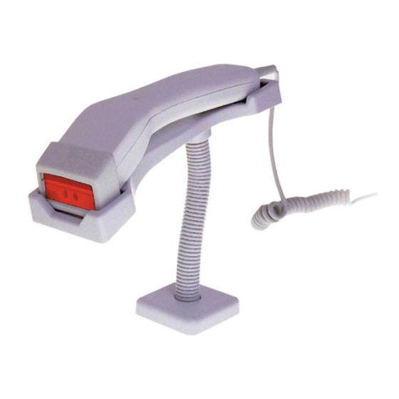
Page 18: Parts Of The Ms951
Parts of the MS951 Coil Cable Green and Red LEDs ScanQuest™ Infrared Object Sensor Laser Output Window Figure 1 When the red LED is on, this indicates that Green and Red LEDs the laser is on. When the green LED flashes on, the scanner has read a bar code success- fully. -
Page 19: Components Of The Ms900 Series Stand
Components of the MS900 Series Stand The following are the components used to build the MS900 series stand (MLPN: 45482): Figure 2 Cradle Wood Screws Stand Cover Internal Lock Washer Stand Base Flexible Shaft Installation of the MS900 Series Stand Use the 2½... - Page 20 Figure 3 Figure 4 Figure 5...
-
Page 21: Audible Indicators
Audible Indicators When the MS951 scanner is in operation, it provides audible indications. These sounds indicate the status of the scan and scanner. When the scanner first receives power, the red LED One Beep will blink, followed by the green LED, and then the scanner will emit one beep. -
Page 22: Visual Indicators
Visual Indicators There is a red and green LED at the top of the scanner. These LEDs indicate the status of the scan and scanner. Illumination of the LEDs will not occur if No Red or Green the scanner is not receiving power from the PC and if the scanner is receiving power but has remained dormant for a specified time thus turning the laser and motor off. - Page 23 Signaux optiques Sur la partie supérieure du scanner se trouvent une diode LED rouge et une diode LED verte. Quand le scanner est sous tension, les diodes rouge et verte clignotantes ou allumées vous informent sur l'état de palpage et de scanner. Ni la diode rouge, ni la diode verte n'est allumée Il existe deux raisons possibles quand les diodes ne s'allument pas.
- Page 24 Optische Anzeigen Auf der Oberseite des Scanners befinden sich eine rote und eine grüne Leuchtdiodenanzeige. Ist der Scanner eingeschaltet, so geben Ihnen die blinkenden oder feststehenden Leuchtdiodenanzeigen Aufschluß über den Scannerstatus. Weder rote oder Es gibt zwei mögliche Gründe, weshalb die Leuchtdiodenan- noch grüne zeigen nicht aufleuchten.
- Page 25 Segnali ottici Sulla parte superiore dello scanner si trovano due diodi luminosi: uno rosso e uno verde. Quando lo scanner è inserito, i diodi luminosi, che possono o essere accesi in continu- azione o lampeggiare, Vi informano sullo stato della scansione e dell’apparecchio. Né...
-
Page 26: Labels
Label Locations The MS951 scanner is either a CDRH Class II laser system or an IEC Class 1 Laser System. The unit will have a CDRH Class II caution label or an LASERKLASSE 1 label affixed below the model number. The model number label is on the bottom of the scanner’s head. -
Page 27: Ir Sensor Activation
IR Sensor Activation The scanning process is initiated by an infrared (IR) device that is below the output window. The signal extends approximately eight (8) inches beyond the output window in long range mode and in short rang mode, it extends approximately three (3) inches (Refer to Figure 6). -
Page 28: Scan Field
Scan Field The depth of field for the scanner is from the face of the output window to five (5) inches (Refer to Figure 7). If the scanner is in the stand, present the bar code to the scanner. When holding the scanner, position the output window within five inches of the bar code. -
Page 29: Ms951 - Depth Of Field And Symbol Specification
MS951 - Depth of Field and Symbol Specification (Refer to Figure 8) Code Type Minimum Small Code Density Depth of Field Element Mil. (1/1000") UPC/EAN 10.4 0.0cm - 10.3cm (0" - 4") UPC/EAN 13.0 100% 0.0cm - 12.8cm (0" - 5") - Page 30 Figure 8...
-
Page 31: Ms961 - Depth Of Field And Symbol Specification
MS961 - Depth of Field and Symbol Specification (Refer to Figure 9) Code Type Minimum Small Code Density Depth of Field Element Mil. (1/1000") UPC/EAN 10.4 0.0cm - 7.7cm (0" - 3") UPC/EAN 13.0 100% 0.0cm - 10.3cm (0" - 4") Code 39 Very High 0.0cm - 3.8cm... - Page 32 Figure 9...
-
Page 33: Maintenance
Maintenance Smudges and dirt can interfere with the proper scanning of a bar code. Therefore, the output window will need occasional cleaning. 1. Spray glass cleaner onto lint free, non-abrasive cleaning cloth. 2. Gently wipe the scanner window. Applications and Protocols The model number on each scanner includes the scanner number and communications protocol. -
Page 34: Ms951 Hand-Held Laser Scanner Specifications
Appendix A MS951 Hand-Held Laser Scanner Specifications Application: Hand-Held Laser Bar Code Scanner Max. Radiant Power: Class II laser product - 1.0 mW Laserklasse 1 - 0.5 mW Light Source: VLD 675 ± 5nm CDRH: Class II laser product IEC: Class 1 laser product;... - Page 35 Operational Depth of Field, UPC 100%: 0.0mm to 125mm (0" to 5") Scan Speed: 36 scan lines per second Scan Pattern: Single scan line Indicators: LED: red = laser on green = good read, decoding Beeper Operation: 3 tones or no beep Maintenance: Clean output window periodically Decode Capability:...
-
Page 36: Ms951 Hand-Held Laser Scanner W/Kbw Specifications
MS951 Hand-Held Laser Scanner with Built-in PC Keyboard Wedge Interface Specifications Application: Hand-Held Laser Scanner Light Source: VLD 675 ± 5nm CDRH: Class II laser product IEC: Class 1 laser product; EN 60825 Sept. 91 UL/CSA/TUV: UL Listed, UL114; CSA certified, C22.2 No. 950, UL 1950;... - Page 37 Operational Depth of Field, UPC 100%: 0.0mm to 125mm (0" to 5") Scan Speed: 36 scan lines per second Scan Pattern: Single scan line LED Indicators: red = laser on green = good read, decoding Beeper Operation: User Selected Beep on “Good Read” Maintenance: Clean output window periodically Decode Capability:...
-
Page 38: Default Settings
Appendix B Default Settings The scanner is shipped from the factory programmed to a set of default conditions. The default parameter of the scanner is marked with an asterisk ( * ) in the charts on the following pages. If an asterisk is not in the default column then the default setting is Off or Disabled. - Page 39 Parameter Default OCIA RS-232 Light Keyboard 46XX Wedge No Two Second Timeout Razzberry Tone on Timeout No Tone on Timeout Three Beeps on Timeout Beep Before Transmit Beep After Transmit Baud Rate 9600 Parity Space 8 Data Bits 7 Data Bits RTS/CTS Character RTS/CTS Message RTS/CTS...
- Page 40 Parameter Default OCIA RS-232 Light Keyboard 46XX Wedge Emulating IBM 4500 Emulating 3687/4014 Emulating IBM 1520 No Inter Record Delay 25 Millisecond (msc) Inter Record Delay 50 msc Inter Record Delay 125 msc Inter Record Delay Bars High Spaces High Transmit as Scanned Transmit as Code 39 Poll Light Pen 5 Volts...
- Page 41 Parameter Default OCIA RS-232 Light Keyboard 46XX Wedge 5 Digit Supps (Scan) Convert EAN-8 to EAN-13 Bookland (Scan) Supplement Required Mod 43 Check Digit Transmit Mod 43 Check Digit Transmit Start/Stop CLSI Editing (Enable) ITF Check Digit Transmit MOD 10 ITF Check Digit I 2 of 5 Symbol Lengths Variable...
- Page 42 Parameter Default OCIA RS-232 Light Keyboard 46XX Wedge Spain Keyboard Italy Keyboard UK Keyboard IBM KB4700 Financial Keyboard Alt Mode AutoDetection or Caps Lock User-Defined Caps Lock F0H Break Code Transmission 800 Microsecond Delay 7.5 Milisecond Delay 15 Milisecond Delay...
-
Page 43: Pin Assignments For The Coil Cable
Pin Assignments for the Coil Cable The MS951 scanners are terminated to a 10 position shielded modular connector. All of the coil cables (MLPN 44530) for the MS951 scanner are terminated the same. The difference between versions is the end of the cable going into the scanner. -
Page 44: Pin Assignments For The Mca (Dec9S)
Pin Assignments for the MCA951 (DEC9S) Located on the MCA is a 9-pin female D-type connector used to connect the MCA to the host device. The output signals on the 9-pin host end of the MCA are dependent upon which version of the scanner that is being used. The following is a list of the pin assignments for the different versions: Version “9”... -
Page 45: Pin Assignments For The 5-Pin Din And 6-Pin Din (Kbw)
The coil cable is terminated with a 5-pin DIN female connector on one end, and a 6-pin mini DIN male on the other. Metrologic will supply an adaptor cable with a 5-pin DIN male connector on one end and a 6-pin mini DIN female connector on the other. -
Page 46: Warranty And Disclaimer
This warranty is limited to repair, replacement or refund at Metrologic’s discretion. Faulty equipment must be returned to the Metrologic facility in Blackwood, New Jersey or Puchheim, Germany. To do this, contact Metrologic Customer Service/Repair for a Returned Material Authorization (RMA) number. - Page 47 Il leur est également réservé le droit de procéder à des modifications de cette brochure sans avoir à en avertir qui que ce soit. Metrologic se réserve en outre le droit de procéder à des modifications du produit qui y est décrit.
-
Page 48: Notices
Appendix E Notices Notice This equipment has been tested and found to comply with limits for a Class A digital device, pursuant to Part 15 of the FCC Rules. These limits are designed to provide reasonable protection against harmful interference when the equipment is operated in a commercial environment. This equipment generates, uses and can radiate radio frequency energy and, if not installed and used in accordance with the instruction manual, may cause harmful interference to radio communications. - Page 49 Anmerkung Nach Überprüfung dieses Geräts wurde festgestellt, daß es den Grenzwerten für Digitalgeräte der Klasse A gemäß Teil 15 der Richtlinien der US-amerikanischen Bundesbehörde für das Fernmeldewesen entspricht. Diese Grenzwerte wurden festgelegt, um einen angemessenen Schutz gegen schädliche Auswirkungen bei Einsatz des Geräts in einer Ladenumgebung zu gewähren. Das Gerät erzeugt und verwendet Hochfrequenzenergie und kann diese ausstrahlen, und kann, falls es nicht gemäß...
-
Page 50: Patents
Appendix F Patents “Patent Information This METROLOGIC product may be covered by one or more of the following U.S. Patents: U.S. Patent No. 4,360,798; 4,369,361; 4,387,297; 4,460,120; 4,496,831; 4,593,186; 4,607,156; 4,673,805; 4,736,095; 4,758,717; 4,816,660; 4,845,350; 4,896,026; 4,923,281; 4,933,538; 4,992,717; 5,015,833;... -
Page 51: Index
Index Default Settings 33-37 Accessories Depth of field 23-27, 30, 32 AC input/outlet 3, 5, 6, 29 Dimensions 29, 31 Adaptor Disclaimer cable 3, 8, 10, 40 3, 5-7, 13, 39 Application 3,7, 8, 9, 11, Electrical 30, 32 28, 29, 31, 39 30, 32 Approvals External power supply... - Page 52 Label(s) 21 Red led 1, 4-6, 13, 16, 17 LEDs 1, 4-6, 14, 17, 18, 29, 31 Repair 41 Light levels 30, 32 Rights Light source 29, 31 property List warranty LTPN 29, 39, 40 Roll, pitch, yaw 30, 32 RS-232 3-5, 28, 30, 38, 39 Maintenance 3, 5-7 13, 39...