
Related Manuals for Metrologic ARGUSSCAN MS7220


Summary of Contents for Metrologic ARGUSSCAN MS7220
- Page 1 METROLOGIC INSTRUMENTS, INC. MS7220 Argus Presentation ™ SCAN Laser Scanner Installation and User’s Guide...
- Page 3 São Paulo, SP, Brasil Copyright © 2002 by Metrologic Instruments, Inc. All rights reserved. No part of this work may be reproduced, transmitted, or stored in any form or by any means without prior written consent, except by reviewer, who may quote brief passages in a review, or provided for in the Copyright Act of 1976.
-
Page 4: Table Of Contents
ABLE OF ONTENTS Introduction....................1 Scanner and Accessories................1 Getting Started ....................3 Installation for OCIA Interface ...............5 Installation for Keyboard Wedge Interface ............7 Installation for Stand-Alone Keyboard Interface ..........8 Installation for RS232 or Light Pen Interfaces ..........9 Installation of an Auxiliary Scanner..............11 Scanner Parts....................13 The Multi-Function Button ................14 Audible Indicators ..................15... -
Page 5: Introduction
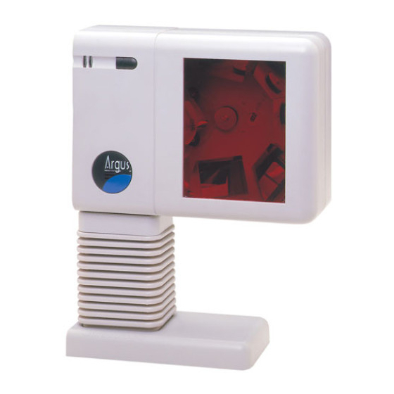
NTRODUCTION ™ ArgusScan is an aggressive, omnidirectional laser barcode scanner ideal for retail, convenience, liquor, and specialty store applications. Engineered with a large, easy-to-find optimal scan area, ArgusScan increases the first pass read rate for maximum productivity. ArgusScan is equipped with a multitude of standard features including: •... - Page 6 CANNER AND CCESSORIES ONTINUED The following items are dependent on the type of MS7220 Kit ordered. Some items may not be included in your kit. • AC to DC Power Transformer - Regulated 5.2V@ 650 mA output • One of the following may be included: •...
-
Page 7: Getting Started
ETTING TARTED Tools needed: • Phillips head screwdriver • ¼”-20 wrench • Drill with a #39 drill bit (drill for hard-mount installation only) Slide off the cable cover. Slide off the horizontal stand. Slide on the cable door and Loosen the lock nut, push back remove the foam insert. - Page 8 ETTING TARTED Return the metal base plate to its Return the foam insert to its original position then tighten the original position then slide lock nut. the horizontal stand back into place on the scanner. Before continuing, determine what communication interface is needed then follow the installation procedure for that interface on pages 5-11.
-
Page 9: Installation For Ocia Interface
OCIA I NSTALLATION FOR NTERFACE To power the unit with an external power supply: Follow the “Getting Started” steps on page 3. Turn off the host system. Connect the PowerLink cable to the jack labeled “OCIA ” on the MS7220. Connect the other end of the PowerLink cable to the host. - Page 10 OCIA I NSTALLATION FOR NTERFACE ONTINUED To power the unit from the host device: For OCIA only) Follow the “Getting Started” steps on page 3. Turn off the host system. Connect the PowerLink cable to the jack labeled “OCIA” on the MS7220. Connect the other end of the PowerLink cable to the host.
-
Page 11: Installation For Keyboard Wedge Interface
NSTALLATION FOR EYBOARD EDGE NTERFACE Follow the “Getting Started” steps on page 3. Turn off the host system. Disconnect the keyboard from the host. Connect the PowerLink cable to the jack labeled “Keyboard Wedge ” on the MS7220. Connect the “Y” end of the PowerLink cable to the keyboard and the keyboard port on the host. -
Page 12: Installation For Stand-Alone Keyboard Interface
NSTALLATION FOR TAND LONE EYBOARD NTERFACE Follow the “Getting Started” steps on page 3. Turn off the host system. Disconnect the keyboard from the host. Connect the PowerLink cable to the jack labeled “Stand-Alone Keyboard” on the MS7220. Stand-Alone Connect the other end of the PowerLink Keyboard cable to the keyboard port on the host. -
Page 13: Installation For Rs232 Or Light Pen Interfaces
RS232 NSTALLATION FOR IGHT NTERFACES Follow the “Getting Started” steps on page 3. Turn off the host system. Connect the PowerLink cable to the jack labeled “RS232 or Light Pen” on the MS7220. Connect the other end of the PowerLink cable to the host. RS232 Before continuing verify that the powerlink cable is connected to the... - Page 14 RS232 NSTALLATION FOR IGHT NTERFACES Step 10, page 9 continued. For RS232 Communication: Recall Defaults Scan 1 ³ Enable RS-232 Scan 2 ³ For Light Pen Communication: Recall Defaults Scan 1 ³ Enable Light Pen/Wand Scan 2 ³...
-
Page 15: Installation Of An Auxiliary Scanner
NSTALLATION OF AN UXILIARY CANNER Turn off the host system. Connect the round end of the PowerLink RS232 AUX cable 54-54667A ] to the RS232 jack of the auxiliary scanner. MLPN Connect the other end of the PowerLink RS232 AUX cable into the 1 jack from the left side of the MS7320. - Page 16 NSTALLATION OF AN UXILIARY CANNER 11. Configure the auxiliary scanner to send formatted data to the MS7220. Normal slave mode operation will only require reserve Code 32 to be set in the auxiliary scanner. The following bar code applies for all scanners, except the MS6720, to be used as an auxiliary scanner.
-
Page 17: Scanner Parts
CANNER ARTS Output Window Red LED Green LED Speaker Side Cover Cable Door Cable Jack Cover Horizontal Mount Base Multi-Function Button (see page 14) Cable Connection Area Figure 7a: Scanner Parts Foam Insert Figure 7b: Scanner Parts... -
Page 18: The Multi-Function Button
ULTI UNCTION UTTON Figure 8a: Multi-Function Button HANGING THE EEPER hort (<3 second) depression and the beeper tone will change. The new tone will be heard, followed by a short pause. Then two more of the new tones will be heard signifying the new setting has been stored in memory. -
Page 19: Audible Indicators
UDIBLE NDICATORS When the MS7220 scanner is in operation, it provides audible feedback. These sounds indicate the status of the scanner. Eight settings are available for the tone of the beep (normal, 6 alternate tones and no tone). To change the tone, use the Multi-Function Button or refer to the ®... -
Page 20: Failure Modes
AILURE ODES Flashing Green and One Razzberry Tone This indicates the scanner has experienced a laser subsystem failure. Return the unit for repair at an authorized service center. Flashing Red and Green and Two Razzberry Tones This indicates the scanner has experienced a motor failure. -
Page 21: Visual Indicators
ISUAL NDICATORS There is a red LED and a green LED on the front of the MS7220. When the scanner is on, the flashing or constant illumination of the LEDs indicates the status of the current scan and the scanner. No Red or Green LED The LEDs will not be illuminated if the scanner is not receiving power from the host or transformer. -
Page 22: Labels
ABELS Each scanner has a label on the back of the unit. The label contains information such as the model number, date of manufacture, and the serial number. Additional CE and caution information has been molded into the back of the case. The following is an example of the back of the case with the label and molded text. -
Page 23: Depth Of Field Specifications
EPTH OF IELD PECIFICATIONS 100% UPC B ASED ON ODES default) Depth of Field ( Figure 10: Top View of Depth of Field Figure 11: Side View of Depth of Field Specifications subject to change without notice. -
Page 24: Depth Of Field By Minimum Bar Code Element Width
EPTH OF IELD BY INIMUM LEMENT IDTH 100% UPC B ASED ON ODES Depth of Field (Default) Figure 12: Top View of Depth of Field Minimum Bar Code Element Width mils 10.4 Specifications subject to change without notice. - Page 25 EPTH OF IELD BY INIMUM LEMENT IDTH 100% UPC B ASED ON ODES Depth of Field (Default) Figure 13: Side View of Depth of Field Minimum Bar Code Element Width mils 10.4 Specifications subject to change without notice.
-
Page 26: Troubleshooting Guide
ROUBLESHOOTING UIDE The following guide is for reference purposes only. Contact a Metrologic representative at 1-800-ID-METRO or 1-800-436-3876 to preserve the limited warranty terms. MS7220 Series Troubleshooting Guide SYMPTOMS POSSIBLE CAUSE(S) SOLUTION All Interfaces No LEDs, beep No power is being Check transformer, outlet or motor spin supplied to the... - Page 27 ROUBLESHOOTING UIDE ONTINUED SYMPTOMS POSSIBLE CAUSE(S) SOLUTION The unit powers Scanning a particular UPC/EAN, Code 39, up, but does symbology that is not interleaved 2 of 5, Code 93, not scan and/or enabled Code 128 and Codabar are beep enabled by default. Verify that the type of bar code being read has been selected...
- Page 28 ROUBLESHOOTING UIDE ONTINUED SYMPTOMS POSSIBLE CAUSE(S) SOLUTION Scanner beeps The bar code may Check if it is a check at some bar have been printed digit/character/or border codes and NOT incorrectly problem for others of the same bar code symbology Scanner beeps The scanner is not Check if check digits are set...
- Page 29 ROUBLESHOOTING UIDE ONTINUED SYMPTOMS POSSIBLE CAUSE(S) SOLUTION Alpha Enable Caps Lock detect characters Computer is in Caps setting of the scanner to show as lower Lock mode detect whether the PC is case operating in Caps Lock Everything These characters may works except not be supported by Try operating the scanner in...
- Page 30 ROUBLESHOOTING UIDE ONTINUED SYMPTOMS POSSIBLE CAUSE(S) SOLUTION Power-up OK Com port not Check to make sure that the and scans OK operating properly. baud rate and parity of the but does not scanner and the communicate communication port match properly to the and the program is looking host.
-
Page 31: Rs232 Demonstration Program
RS232 D EMONSTRATION ROGRAM If an RS232 scanner is not communicating with your IBM compatible PC, key in the following BASIC program to test that the communication port and scanner are working. This program is for demonstration purposes only. It is only intended to prove that cabling is correct, the com port is working, and the scanner is working. -
Page 32: Applications And Protocols
PPLICATIONS AND ROTOCOLS The model number on each scanner includes the scanner number and factory default communications protocol. Version Scanner Communication Protocol(s) Identifier RS232, Light Pen, Keyboard Wedge, Stand- 7220 Alone Keyboard, OCIA, Low Speed Option The MS7220 with Built-in PC Keyboard Wedge Interface is designed to be used for keyboard emulation only. -
Page 33: Design Specifications
ESIGN PECIFICATIONS MS7220 D ESIGN PECIFICATIONS PERATIONAL Light Source: VLD 650 ± 10 nm Laser Power: 0.678 mW maximum Depth of Field: 0 mm to 215 mm 8.5" at default (programmable) Scan Speed: 2000 scans/second Scan Pattern: 5 fields of 4 parallel lines (omnidirectional) Scan Lines: Min Bar Width: 0.13 mm (5.2 mil) - Page 34 ESIGN PECIFICATIONS MS7220 D ESIGN PECIFICATIONS LECTRICAL Input Voltage: 5.2VDC ± 0.25V Power: 1.9 W Operating Current: 360 mA DC Transformers: Class II; 5.2 V @ 650 mA CDRH: Class IIa; EN 60825-1: 1994/A11:1996 Laser Class: Class 1 EMC: FCC, ICES-003 & EN 55022 Class A NVIRONMENTAL Operating Temperature: 0°C to 40°C (32°F to 104°F)
-
Page 35: Default Settings
EFAULT ETTINGS Many functions of the scanner can be "programmed" - that is, enabled or disabled. The scanner is shipped from the factory programmed to a set of default conditions. The default parameter of the scanner has an asterisk ( * ) in the charts on the following pages. If an asterisk is not in the default column then the default setting is Off or Disabled. - Page 36 EFAULT ETTINGS ONTINUED Light Parameter Default OCIA RS-232 46XX DTS/NIXDORF NCR F NCR S Poll Light Pen Source Beeper Tone Normal Beep/Transmit Before Sequence Transmit Communication Timeout None Razzberry Tone on Timeout Three Beeps on Timeout No Beeps on Timeout Enter Power Save Mode 10 mins.
- Page 37 EFAULT ETTINGS ONTINUED Light Parameter Default OCIA RS-232 46XX Convert EAN-8 to EAN- Transmit UPC-A Number System Transmit UPC-A Manufacturer ID# Transmit UPC-A Item ID# Transmit Codabar Start/Stop Characters CLSI Editing (Enable) Transmit Mod 43 Check Digit on Code 39 Transmit Code 39 Stop/Start Characters Transmit Mod 10/ITF...
- Page 38 EFAULT ETTINGS ONTINUED Light Parameter Default OCIA RS-232 46XX Carriage Return Line Feed - disabled by default in KBW Tab Prefix Tab Suffix "DE" Disable Command "FL" Laser Enable Command DTR Handshaking Support RTS/CTS Handshaking Character RTS/CTS Message RTS/CTS XON/XOFF Handshaking ACK/NAK Two Digit Supplements...
- Page 39 EFAULT ETTINGS ONTINUED Light Parameter Default OCIA RS-232 46XX Coupon Code 128 code Programmable Code 7 avail. Lengths Programmable Prefix 10 avail. Characters Suffix Characters Prefixes for individual Code Types Editing Inter Scan-Code Delay Programmable (100 µsec 800 µsec steps) Function/Control Key Support Minimum Element Width...
- Page 40 EFAULT ETTINGS ONTINUED Default settings for “Aux” interface The slave scanner and the MS7220 always communicate via RS232. Data is relayed to the host via various primary interfaces. Light Parameter Default OCIA RS-232 46XX Aux Baud Rate 38400 Aux parity space Aux data bits Aux stop bits...
-
Page 41: Ms7220 Stands
MS7220 S TANDS Vertical Stand Kit [ 46-46405 ] MLPN See page 38 for installation instructions. Kit Includes: a. #8 x 1 round head wood screw 18-18057 ] Qty. 4 MLPN b. M3 x .5 x 6mm pan head screw 18-18670 ] Qty. -
Page 42: Vertical Stand Installation
MS7220 S TANDS Vertical Stand Installation [ 46-46405 ] MLPN Remove the three screws Disassemble the horizontal stand and securing the cable cover to the remove the horizontal cover plate. unit and slide it up and off the scanner. Disconnect the cable and slide the horizontal stand up and off the unit. -
Page 43: Optional Flex Stand Installation
MS7220 S TANDS Optional Flexible Stand Installation [ 46-46404 ] MLPN Remove the three screws Disassemble the horizontal stand. Remove securing the cable cover to the the lock nut and the short coupler. They will unit and slide it up and off the not be used on the flex stand. -
Page 44: Scanner And Cable Terminations
CANNER AND ABLE ERMINATIONS Scanner Pinout Connections The MS7220 scanner interfaces terminate to 10-pin modular jacks located on the back of the unit. The serial # label indicates the interface enabled when the scanner is shipped from the factory. MS7220-12 OCIA Function Ground... -
Page 45: Cable Connector Configurations
CANNER AND ABLE ERMINATIONS ONTINUED MS7220 Auxilary Port RS232 IN Only Function Ground RS-232 Receive Input RS-232 Transmit Output RTS in CTS out Cable Connector Configurations “Standard” PowerLink cable 9-pin D-type female connector to the PC Function Shield Ground RS-232 Transmit Output RS-232 Receive Input DTR Input 9-Pin D-Type Connector... - Page 46 CANNER AND ABLE ERMINATIONS ONTINUED Cable Connector Configuration The PowerLink cable is terminated with a 5-pin DIN female connector on one end, and a 6-pin mini DIN male on the other. PowerLink Cable 5-Pin DIN, Female 6-Pin DIN, Male Metrologic will supply an adapter cable with a 5-pin DIN male connector on one end and a 6-pin mini DIN female connector on the other.
-
Page 47: Limited Warranty
METROLOGIC EXCEED THE ACTUAL AMOUNT PAID TO METROLOGIC FOR THE PRODUCT. METROLOGIC RESERVES THE RIGHT TO MAKE ANY CHANGES TO THE PRODUCT DESCRIBED HEREIN. Corporate Headquarters Metrologic Instruments, Inc. Customer Service: 1-800-ID-METRO 90 Coles Road Tel: 856-228-8100 Blackwood, NJ 08012-4683 Fax: 856-228-6673 Email: info@metrologic.com... -
Page 48: Notices
OTICES Notice This equipment has been tested and found to comply with limits for a Class A digital device, pursuant to Part 15 of the FCC Rules. These limits are designed to provide reasonable protection against harmful interference when the equipment is operated in a commercial environment. This equipment generates, uses and can radiate radio frequency energy and, if not installed and used in accordance with the instruction manual, may cause harmful interference to radio communications. -
Page 49: Patents
OTICES ONTINUED European Standard Warning This is a class A product. In a domestic environment this product may cause radio interference in which case the user may be required to take adequate measures. Funkstöreigenschaften nach EN 55022:1998 Warnung! Dies ist eine Einrichtung der Klasse A. Diese Einrichtung kann im Wohnbereich Funkstörungen verursachen;... -
Page 50: Index
NDEX Accessories .......1 Maintenance ......18 Adapter ........2, 42 Mechanical.......29 Audible........15 Min Bar Width ......29 Autodiscriminates ....29 Normal Depth of Field....35 Bar Code .....19, 20, 21 Notices.......44, 45 Beep ........15, 32 OCIA 1, 2, 5, 6, 28, 29, 31-36, 40 Cable ... 2-9, 11-13, 26, 29, 38-42 Operating Current ....30 Caution ......5, 6, 7, 8, 9 Operation ......29, 44... - Page 52 April 2002 Printed in USA 0 0 - 0 2 5 5 4 A...