
Related Manuals for Pentair Pool and Spa Control System SunTouch


Summary of Contents for Pentair Pool and Spa Control System SunTouch
- Page 1 SunTouch Pool and Spa Control System Installation and User’s Guide IMPORTANT SAFETY INSTRUCTIONS READ AND FOLLOW ALL INSTRUCTIONS SAVE THESE INSTRUCTIONS...
- Page 2 Pentair Water Pool and Spa, Inc. Other trademarks and trade names may be used in this document to refer to either the entities claiming the marks and names or their products. Pentair Water Pool and Spa, Inc. disclaims proprietary interest in marks and names of others.
-
Page 3: Table Of Contents
IMPORTANT SAFETY PRECAUTIONS ... iii Technical Support ... vi Section 1: SunTouch Pool and Spa Control System Overview ... 1 SunTouch Control System Overview ... 1 SunTouch Solar Mode ... 1 SunTouch Pool/Spa Mode ... 1 SunTouch Control Panel ... 2 SunTouch Control Buttons ... - Page 4 Advanced Menu (8/13): System Type ... 24 Advanced Menu (8/13): Reset Factory ... 25 Diagnostics Menu (9/13): Firmware Rev ... 25 Diagnostics Menu: Solar Temp ... 25 Diagnostics Menu: Self Test ... 25 Circuit Functions Menu (10/13) ... 26 Assigning Circuit Functions ... 26 Freeze Protection ...
- Page 5 Connecting SunTouch to Heaters ... 57 Connecting to a standard heater ... 57 Connecting to a Laars heater ... 58 Connecting to a Pentair MiniMax, Pentair MasterTemp ... 58 Connecting to a Sta-Rite heater ... 58 SunTouch Solar System Installation ... 59 SunTouch Solar System Start-Up ...
-
Page 6: Important Safety Precautions
IMPORTANT SAFETY PRECAUTIONS Important Notice: Attention Installer: This manual contains important information about the installation, operation and safe use of this product. This information should be given to the owner and/or operator of this equipment. When installing and using this electrical equipment, basic safety precautions should always be followed, including the following: WARNING: IMPORTANT SAFETY INSTRUCTIONS PERTAINING TO A RISK OF FIRE, ELECTRIC SHOCK, OR INJURY TO PERSONS. -
Page 7: Safety Notice
IMPORTANT SAFETY PRECAUTIONS General Installation Information 1. All work must be performed by a licensed electrician, and must conform to all national, state, and local codes. 2. Install to provide drainage of compartment for electrical components. 3. If this system is used to control underwater lighting fixtures, a ground-fault circuit interrupter (GFCI) must be provided for these fixtures. -
Page 8: Technical Support
Technical Support Sanford, North Carolina (8 A.M. to 5 P.M. ET) Moorpark, California (8 A.M. to 5 P.M. PT) Phone: (800) 831-7133 Fax: (800) 284-4151 Web sites visit www.pentairpool.com and staritepool.com SunTouch Pool and Spa Control System Installation and User’s Guide... -
Page 9: Section 1: Suntouch Pool And Spa Control System Overview
SunTouch Control System Overview Welcome to the Pentair SunTouch pool and spa control system - The next generation in intelligent control systems. The SunTouch control system can be easily configured to operate in “Solar Only” mode for solar systems, or in “Pool/Spa” mode for shared equipment systems, or single body pool or spa systems. The SunTouch system is also compatible with the IntelliChlor ®... -
Page 10: Suntouch Control Panel
SunTouch Control Panel Use the SunTouch control panel buttons to program and control pool and spa operations. You can schedule daily operations to run automatically using the SunTouch menu features, and manually adjust temperature settings, switch lights on and off, and setup pool/spa equipment. The SunTouch LCD displays the current temperature settings, current time and equipment status information. - Page 11 Control Buttons (Continued) ➂ Left button: and return to the Main status screen. (-) TEMP Right button: or parameter, or scroll through the available selected menu items. To exit the Main menu, press the Left arrow button. (+) TEMP (-) TEMP) and (+)TEMP button temperature controls: Set temperature Actual temperature the (-) TEMP button to lower set temperature or the (+) TEMP button to raise the set...
-
Page 12: Suntouch Main Status Screen (Solar Only Mode)
SunTouch Main Status Screen (Solar Only) The SunTouch “Solar Only” main status screen display description is given below. Lower current set point temperature setting AIR temperature: In “Solar Only” mode the main screen toggles the display between the current AIR temperature and the actual and set point water temperature. -
Page 13: Operating Suntouch In Solar Only Mode
Operating SunTouch in Solar Only Mode SunTouch Solar Only mode In “Solar only” mode, you can control your SunTouch solar system to heat your pool and spa. From the control panel you can set the temperature, and the differential temperature controls for the water up heat up to the set temperature. -
Page 14: Adjusting The Water Temperature Setting (Solar Only Mode)
Solar Only Menus The SunTouch “Solar Only” mode menus are shown below: Set Water Temp System Control System Mode Time Set Start Temp Diff StopTemp Diff Solar Freeze Cleaner Freeze Air Sensor Adjusting the water temperature setting (Solar Only mode) If you have already set the pool and spa water temperature in the “SET WATER TEMP”... -
Page 15: System Control
Solar Only Menus (Continued) System Control Use this feature to operate the SunTouch solar system in “AUTO” mode, or manually switch solar on or off. Menu button: The Set Water Temp settings is displayed. Right button: Press the button to display the “System Control” setting. System Control Up/Down button: The selections are: AUTO... -
Page 16: Start And Stop Temp Differentials
Solar Only Menus (Continued) Start and Stop Temp Differentials: to start and stop solar water heating. Menu button: The Solar Status setting is displayed. Right button: Press the button until the “Start Temperature Deferential” setting is Start Tem Diff displayed. Temp Diff: 6°... -
Page 17: Freeze Protection In Solar Only Mode
Freeze Protection in Solar Only mode The SunTouch freeze protection function is active once the optional air sensor is installed and enabled (see page 8). Freeze protection is enabled whenever the outside temperature is 36º F or lower. When freezing conditions are detected by the air sensor the filter pump will be switched on and water will circulate continuously through the system. -
Page 18: Selecting The Heat Source
Adjusting the water temperature setting in Pool/Spa mode • Adjusting the pool water temperature: the “Pool” circuit. To activate the circuit, press the button, then press the Up or Down • Press the Left or Right source is displayed on the lower display line. The spa water temperature can be adjusted from 40° F to 104°... -
Page 19: Suntouch Main Status Screen (Pool/Spa Mode - Shared Equipment)
SunTouch Main Status Screen (Pool/Spa mode - Shared Equipment) Use the SunTouch display to view daily pool and spa operations. The “Schedule” menu feature (page 17) is typically used for these operations. For manual spa operation, pressing the SPA Up button will activate the spa circuit, switch on the filter pump, display the current spa water, air temperature setting, and heat source. -
Page 20: Pool/Spa Mode Menus (Dual Body Of Water)
Pool/Spa Mode Menus (Shared Equipment) Circuit On/Off 1/13 Filter Pump: [On/Off] - Default Off - See page 13 AUX 1, AUX 2, AUX 3 [On/Off] Heat 2/13 Pool Temperature [40˚ F - 104˚ F] or [4˚ C - 40˚ C] - see page 14 Pool Heat Source [Off/Heater/Solar/Solar Prf] - To display "Solar/Solar Prf"... -
Page 21: Menu Descriptions (Pool/Spa Mode)
Pool/Spa Mode Menus The following describes the 13 menus provided for Pool/Spa Mode. Each menu item and it’s number (1 through 13) is displayed on the top line of the main screen. Circuit On/Off Menu (1/13) Use the “Circuit On/Off” feature to manually switch the pool filter pump, AUX 1, AUX 2, and AUX 3 relay output ON or OFF. -
Page 22: Heat Menu (2/13)
Circuit On/Off Menu (1/13) To return to the menu items, press the Left button. Pool 77°F / 79°F 9:45 AM AUX 1 Note: The AUX 1 relay circuit can also be switched on or off using the control panel Down arrow button. When the Down arrow button is pressed to switch the AUX 1 circuit on, AUX 1 is displayed. -
Page 23: Spa Temperature And Heat Source
Heat Menu (2/13) (Continued) Spa Temperature and Heat Source To set the spa temperature and switch the heater on or off: Menu button: Select the Heat menu. Main Menu 2/13 Right button: Select the spa temperature setting. Heat Up/Down button: Press the button until the Spa Temperature setting displays. Adjust to the desired spa set point temperature Spa Temperature (from 40°... -
Page 24: Delay Cancel Menu (3/13)
The Delay Cancel feature is mainly for use by service technicians when it’s necessary to shut the filter pump off immediately, and know the heater has not been running. Heaters manufactured by Pentair do not require this cool-down period and do not need the delay to be set up. -
Page 25: Schedules Menu (4/13)
Schedules Menu (4/13) Scheduled start and stop programs can be assigned to pool, spa and auxiliary circuits (AUX 1, AUX 2, AUX 3) functions. The start and stop times can be programed to run automatically within a 12 hour period. The default run time for a scheduled circuit is 8:00 AM to 5:00 PM which can be adjusted in 15 minutes increments. -
Page 26: Schedule Your Spa Or Pool
Schedules Menu (4/13) Schedule your Spa or Pool You can set a daily start and stop time to switch the filter pump on and rotate the pool or spa valves into the “Spa” or “Pool” position. The heater will automatically heat the spa or pool water up to the set point temperature as set in the “Heat”... -
Page 27: Clock Menu (5/13)
Clock Menu (5/13) Use the Clock menu to set the SunTouch system time. The current time in hours, minutes and AM/PM is displayed on the main screen. The system clock settings are used for the SunTouch system scheduled operations. The SunTouch system clock will continue to run even if power is removed from the SunTouch system at the enclosure. -
Page 28: Solar Menu (6/13)
Solar Menu (6/13) Use the solar settings to setup solar or configure solar as a heat pump: Setting Up Solar Control: Ensure that the solar temperature sensor is installed. Installing Solar Heating: First, install the solar sensor at the collectors and connect to the SunTouch enclosure. -
Page 29: Valves Menu (7/13)
Valves Menu (7/13) This feature allows you assign a circuit to the extra valve output (Valve C) on the SunTouch motherboard. The SunTouch system can drive the auxiliary valve actuator for applications such as solar heating and water features and for freeze protection. By assigning any one of the auxiliary (AUX 1, AUX 2, AUX 3) circuits to control the valve actuator, you can conserve auxiliary circuits for high voltage relays for controlling pumps and lights. -
Page 30: Advanced Menu (8/13): Pool/Spa Delays
Advanced Menu (8/13): Pool/Spa Delays The pool and spa delays feature allows you to assign a delay function to the following equipment. • Heater Cool-Down Delay Cancel: Shuts Filter Pump off immediately. Some heaters require a cool-down cycle before being switched off. This can be setup to run the filter pump an additional ten minutes to dissipate residual heat built up inside the heater combustion chamber. -
Page 31: Advanced Menu (8/13): Calibrate Water, Air And Solar Sensors
Advanced Menu (8/13): Calibrate water, air and solar sensors The SunTouch system includes two temperature sensors for monitoring water and ambient air temperature. An additional air sensor for controlling solar heating systems can also be installed for solar systems. Generally, these sensors are accurate and do not require calibration. -
Page 32: Advanced Menu (8/13): Air Sensor
Advanced Menu (8/13): Air Sensor If an optional ambient air temperature sensor is installed, the sensor must be enabled to display the current air temperature on the main status screen. The optional air temperature sensor is used to protect the system plumbing and equipment against freeze damage. -
Page 33: Advanced Menu (8/13): Reset Factory
Advanced Menu (8/13): Reset Factory SunTouch system configuration data is stored and retained in “Flash” memory in an EEPROM located on the SunTouch motherboard. The SunTouch user system configuration data can be erased to restore the factory defaults settings. If the optional QuickTouch QT4 wireless controller is installed it will need to be reconfigured. Reset to factory default settings Menu button: Select the Advanced menu. -
Page 34: Circuit Functions Menu (10/13)
Circuit Functions Menu (10/13) Assigning Circuit Functions From the Circuit Functions menu you can assign special logic to the auxiliary relay circuits AUX 1 and AUX 2. For example, when setting up an automatic pool cleaner pump, you could assign AUX 1 the circuit function FLOOR CLEANER. -
Page 35: Preset Circuit Functions
Circuit Functions Menu (10/13) Preset Circuit Functions o l l c t i c t i o l l c t i c t i (Continued) l a i . c i t i l i c i t t l i f s / l t l i f l l a... -
Page 36: Settings Menu (11/13): Quicktouch (Qt4) Wireless Remote
Settings Menu (11/13): QuickTouch The QuickTouch QT4 wireless remote controller provides switching of up to four circuits. For example, you can use the QT4 wireless remote to activate the spa circulation, and for operating three auxiliary pieces of equipment (such as heat enabled, lights, jet pump, heat boost, air blower, waterfall, etc.). Each of the four functions on the QT4 wireless controller has an on and an off button. -
Page 37: Pump Menu (12/13)
10 minutes to allow the heater to cool down. Pentair heaters do not require a cool down time. To override the “heater cool-down,” press the Filter Pump button again to switch off the pump. -
Page 38: Intelliflo 4 Pump
Pump Menu (12/13) (Continued) ® IntelliFlo 4 pump From the IntelliFlo 4x160 menu you can assign a circuit for the IntelliFlo 4x160 pump to control four different pump speeds. The pump speed can be adjusted to run from 400 to 3450 RPM in increments of 10 RPM. For more information about the IntelliFlo 4x160 pump, refer to the IntelliFlo 4x160 Installation and User’s Guide (P/N 357269). -
Page 39: Intellichlor Menu (13/13)
IntelliChlor Menu (13/13) The IntelliChlor electronic chlorination system needs to be connected to the SunTouch system to use the following IntelliChlor settings. While in normal operating mode (Pool, Spa mode or Spa Fill (Spillway), SunTouch will control the chlorinator output level. When IntelliChlor is connected to the SunTouch, chlorination levels can only be changed from the SunTouch control panel. -
Page 40: Intellichlor Menu (13/13): Status And Error Messages
IntelliChlor Menu (13/13): Status and Error Messages If an error alert, or warning is detected by IntelliChlor, the error message will be displayed on the SunTouch control panel screen. All status and error messages can be viewed from the IntelliChlor menu. For troubleshooting information, refer to the IntelliChlor Electronic Chlorine Generator User’s Guide (P/N 520589). -
Page 41: Suntouch Main Status Screen (Pool/Spa Mode - Single Body System)
SunTouch Main Status Screen (Pool/Spa Mode - Single Body System) Use the SunTouch display to view the daily operations of your spa or pool. Using the UP arrow button (HI-TEMP) to manually switch the filter pump on and off and activate the heater. LOW temperature control can also be assigned to the UP arrow button. -
Page 42: Hi-Temp / Lo-Temp Circuit Control
High/Low Temperature Circuit Control (Single Body System) HI-TEMP / LO-TEMP Circuit Control HIGH 75°F / 85°F 11:51AM HEATER LOW Temperature control circuit: control button. Use the LOW temperature circuit to switch on the heater (when heater is enabled) and filter pump. -
Page 43: Pool/Spa Mode (Single Body Of Water) Menus
Pool/Spa Mode (Single Body of Water) Menus For menu descriptions, see “The Pool/Spa Mode Menus” on page 13. Circuit On/Off 1/13 Filter Pump: [On/Off] - Default Off - see page 13 AUX 1, AUX 2, AUX 3 [On/Off] Heat 2/13 LOW TEMP [40˚... - Page 44 Blank Page SunTouch Pool and Spa Control System Installation and User’s Guide...
-
Page 45: Section 2: Installation And Setup
SunTouch System Installation Steps Summary The recommended SunTouch system installation steps are: Review, prepare and install SunTouch Power Center (pages 44): Review high voltage connections. Prepare and install the SunTouch Power Center at the equipment pad. AC power for SunTouch should be provided from the main-panel circuit breaker located at the house. -
Page 46: Suntouch Solar Package Contents
SunTouch Solar Package Contents SunTouch Solar (P/N 520819) • SunTouch Power Center - QTY 1 • Valve actuator assembly (P/N 263045) - QTY 1 • Solar valve (P/N 263047) - QTY 1 • Temperature sensors (20 ft. water, solar 40 inches) - QTY 2 SunTouch Solar with non-solar 3-way valve (P/N 520856) •... -
Page 47: Suntouch System Overview
SunTouch System Overview QuickTouch (QT4) Wireless remote kit (P/N 520148) (Optional) Temperature Sensors (Water, Air and Solar) SunTouch enclosure (with two resettable circuit breakers (18 VAC and 24 VAC). Electrical Ratings: Input: 120/240 VAC, 60/50 Hz, 820/410 mA maximum. Output: 120 VAC, 20 FLA/120 LRA, 1.5 HP. -
Page 48: Suntouch Power Center
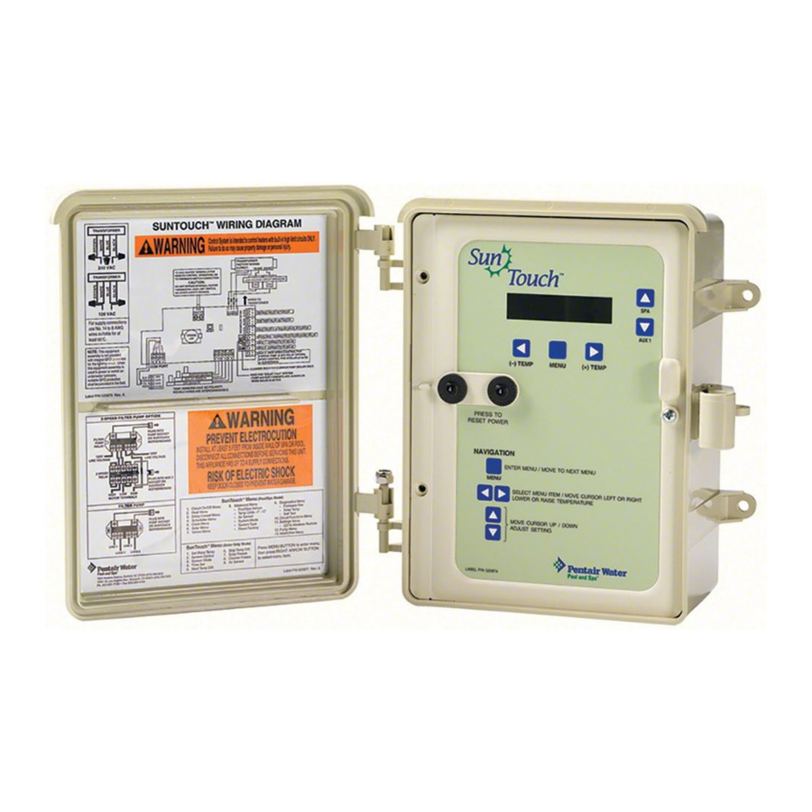
SunTouch Power Center Low voltage push-button Enclosure front door 1” Grommet for low voltage SunTouch Pool and Spa Control System Installation and User’s Guide (Front View) circuit breakers (18 VAC / 24 VAC) Control Panel LCD and buttons wires (Air and water Two ½"... -
Page 49: Plumbing Requirements
Plumbing Requirements It is important that the pool and spa plumbing system be in accordance with local codes and the Recommended Hydraulic Schematics. Before starting, please review the diagrams and the following recommended guidelines: The spa should be at or above the level of the pool. If the spa is attached to the pool, provide a dam between the two bodies of water to allow the spa to overflow into the pool. -
Page 50: Equipment Location
Plumb the solar feed and return lines between the filter and the heater. Install a three-port valve at the feed line. Use a solar valve (P/N 263047)), to allow automatic draining of the panels. A solar booster pump should be used when the distance to the panels exceed 200 ft., or the panels are elevated higher than 25 ft. -
Page 51: Solar Hydraulics System
Solar Hydraulics System Plumb the SunTouch solar system in accordance with recommended hydraulics shown below. • 2” diameter plumbing is advised to ensure maximum flow of water through the solar panels. A solar booster pump should be added if panels are installed at a very high elevation. •... -
Page 52: Suntouch Power Center High Voltage Connections
SunTouch Power Center High Voltage Connections WARNING BEFORE OPENING THE FRONT PANEL OF THE SUNTOUCH POWER CENTER TO ACCESS THE HIGH VOLTAGE COMPARTMENT AND LOW VOLTAGE RACEWAY, SWITCH THE MAIN POWER OFF INTO THE HOME AT THE MAIN CIRCUIT BREAKER BOX, AND SWITCH OFF THE MAIN POWER TO THE SUNTOUCH POWER CENTER. -
Page 53: Grounding And Bonding To The Suntouch Power Center
Grounding and Bonding to the SunTouch Power Center Connect a ground wire from the primary electrical panel to the SunTouch ground bus bar. Also ground each piece of high voltage (120 VAC or 240 VAC) equipment that is connected to the SunTouch Power Center relays. -
Page 54: Preparing The Suntouch Power Center
Preparing the SunTouch Power Center Before mounting the SunTouch Power Center, first open the front door and the front panel to access the conduit knockouts and low voltage raceway. Opening the front panel To access the SunTouch Power Center electronics compartment: 1. -
Page 55: Mounting The Suntouch Power Center
Mounting the SunTouch Power Center The SunTouch Power Center can be mounted on a flat vertical surface, such as a wall or post. Note: Select a convenient location to mount the SunTouch Power Center, making sure that the location is greater than 5 feet from the pool or spa and no further than 15 feet from the pool/spa valve. -
Page 56: Removing Electrical Conduit Knockouts
Removing Electrical Conduit Knockouts Before installing SunTouch power center electrical conduit, read the following recommended guidelines. Remove the power center conduit knockouts as needed: • Determine the number of low and high voltage circuits being used in the SunTouch power center, the conduit size and runs needed based on the wire size, and the number of conductors within the conduit. -
Page 57: Installing Conduit And Wire To The Suntouch Power Center
Installing Conduit and Wire to the SunTouch Power Center • Use No. 14 (min.) to No. 6 (max.) AWG for power relay circuits depending on the power requirement. Be sure to follow all regulation safety codes for the number and size of conductors that can be installed in various sizes of conduit. -
Page 58: Transformer Connections
Transformer Connections High Voltage Wiring The high voltage wiring section is located inside the SunTouch enclosure. The SunTouch system can be connected either to 120 VAC or 240 VAC. The SunTouch system should be wired to receive continuous power (connect directly to sub-panel). The maximum current rating is 820/410 mA at 120/240 VAC 60 Hz/50 •... -
Page 59: Suntouch Motherboard Connections
SunTouch Motherboard Connections The SunTouch system motherboard is mounted onto the back of the control panel located in the Power Center. The motherboard provides the voltage connections to switch the filter pump, heater, auxiliary relays, motorized valves, and connections for temperature sensors. To access the motherboard, refer to “Accessing the SunTouch Motherboard,”... -
Page 60: Accessing The Suntouch Motherboard
Accessing the SunTouch Motherboard The SunTouch motherboard provides connectors for three auxiliary relays, valve actuators and sensors. To access the SunTouch Power Center electronics compartment: 1. Loosen the retaining screw on the front panel. Open the hinged front panel to access the electronics compartment. -
Page 61: Installing Auxiliary Relays
Installing Auxiliary Relays There can be a maximum of three standard auxiliary relays installed in the SunTouch Power Center. Depending on the SunTouch kit, relays may not be included in the kit. Relays must be installed at the site. When using a 2-Speed pump, the optional 2-Speed relay (P/N 520198) can be installed, replacing the standard relay which is located in the right-side of the Power Center. - Page 62 Installing relays (Continued) Standard relay (Location 3): Position the relay (coil facing upward) on top of the mounting studs. Align the relay flanges with the screw holes. Using a 1/4 in nut driver, secure the relay in place with the two retaining screw. 2-Speed Relay (location 3): Position the relay bracket on top of the mounting studs.
-
Page 63: Installing Valve Actuators
Installing Valve Actuators For shared equipment systems there are two motorized valve actuators (CVA-24T, P/N 263045) included with the SunTouch kit. To install a valve actuator: 1. Remove the valve knob, handle and the four screws, from the valve cover (indicated with arrows). 2. -
Page 64: Installing And Connecting Temperature Sensors
Installing and Connecting Temperature Sensors Water Temperature Sensor To install the water sensor: 1. Select a convenient location to mount the water sensor in the plumbing system between the filter pump and filter. Drill a 5/16" diameter hole in one side of the pipe, 2. -
Page 65: Connecting Suntouch To Heaters
Refer to your heater documentation for specific wiring instructions for connecting the heater to an external control (typically using a two-wire remote control connection). For connection to millivolt or line voltage heaters, contact Pentair Technical Support (see page iv). Connecting to a standard heater The following installation instructions are for gas heaters and heat pumps with low voltage thermostats. -
Page 66: Connecting To A Laars Heater
Connecting to a Pentair MiniMax, MasterTemp To connect a Pentair MiniMax, MasterTemp, or Purex Laars heater to SunTouch: 1. Switch the power OFF to the heater. 2. Remove the factory installed jumper from the “Ext Switch” connector. 3. Connect the two-wire cable from J12 on the SunTouch motherboard to the “Ext Switch” terminal as shown below. -
Page 67: Suntouch Solar System Installation
SunTouch Solar System Installation • To ensure maximum flow of water through the solar panels, a solar booster pump should be added if panels are installed at a very high elevation. • It is recommended that the solar panels are mounted in a way that gravity will allow draining whenever the filter pump is not on. -
Page 68: Suntouch Pool/Spa Controller System Start-Up
SunTouch Pool/Spa Controller System Start-Up Perform the following start-up procedures to ensure that the SunTouch enclosure is installed correctly. Before you power up the SunTouch enclosure check the following: Check Electronics Check that the following plugs are seated correctly on the motherboard: •... -
Page 69: Setting Up The Suntouch System For The First Time (After Equipment Installation)
Setting up the SunTouch System for the First Time (after equipment installation) Use the following steps if you are setting up the SunTouch system for the first time. Note: The following setup steps assume that the SunTouch enclosure is installed at the equipment pad and ready for operation. - Page 70 6. Configuring the heater system options Pool/Spa mode (page 14) Set the type of heat source being used (Heater, Solar, Solar Preferred). 7. Configure the QuickTouch wireless remote buttons (page 28) Assign four circuits to the QuickTouch remote buttons. Once you have checked that all buttons operate properly, place labels on remote buttons.
-
Page 71: Section 3: Troubleshooting
Troubleshooting Use the following troubleshooting information to help resolve problems that may occur when using the SunTouch system. If by following the recommended actions you are still unable to resolve the problems, please contact Technical Support (see page vi). Frequently Asked Questions (FAQ) How do I setup a two-speed pump? A two-speed pump operates using two relays and one or more circuits. -
Page 72: Suntouch Error Messages
SunTouch Error Messages Error Messages If the system detects that a sensor is not connected to the SunTouch Power Center or it is defective, an error message is displayed in the Diagnostics menu (page 25). The following lists the sensor errors. "... -
Page 73: Problem Solving A Solar System
Problem Solving a Solar System SunTouch solar is not operating Verify the circuit breaker at sub-panel is not tripped. If the 3 AMP Circuit Breaker on the on SunTouch is tripped, it is most often due to a defective Circuit Board or Valve Actuator. Try disconnecting each one separately to determine which one is at fault. -
Page 74: Temperature Vs. Resistance Data
Temperature vs. Resistance Data SunTouch systems use 10k Ω thermistor sensors. When the solar sensor is disconnected from the SunTouch system, the sensor will read 10k Ω at 77º F (25ºC). Refer to the tables on the following pages for the resistance at other temperatures. -
Page 75: Intellichlor Error Messages
IntelliChlor Error Messages IntelliChlor status and error messages are displayed in the “Chlorinator” menu (see page 32). Use the following information to resolve IntelliChlor system problems. To access the IntelliChlor menu, press Menu > Diagnostics > Chlorinator. System Problem Diagnosis Use the following information to resolve system problems. -
Page 76: Quick Touch Wireless Problems
Problem: The Quick Touch remote will not work, or will not work dependably. g i l c i t . l l g i l n i l l l i n i l c t i y l t s t i s l i s l i... - Page 77 Problem: The Quick Touch remote will not work, or will not work dependably (Continued). s t i t t i y l t y l t i a f y t i t t i n i l SunTouch Pool and Spa Control System Installation and User’s Guide t t i c t i t t i...
-
Page 78: Intelliflo 4X160 Warning And Alarm Conditions
IntelliFlo 4x160 Warning and Alarm Conditions The IntelliFlo 4x160 alarms and warnings are indicated by flashing LEDs on the control panel. For example, if a “Drive Temperature” warning occurs, the LED will blink two times, then Off, then blink two times. This sequence is repeated until the condition is cleared. -
Page 79: Wiring Suntouch To The Intellichlor Salt Chlorine Generator
Wiring SunTouch to the InteliiChlor Salt Chlorine Generator Be sure to check the wire color and function of the IntelliChlor salt chlorine generator before connecting it to the SunTouch COM port on the motherboard. See the wiring table below for the pin configuration. Failure to wire the salt chlorine generator properly can permanently damage the SunTouch system or chlorine generator. - Page 80 Blank Page SunTouch Pool and Spa Control System Installation and User’s Guide...
-
Page 81: Appendix
Emergency Shut-Off switch The SunTouch system can be used for commercial spa applications that require an Emergency Shut-Off (ESO3) switch. It can be installed with new or existing pool and spa system. In the event of an emergency, the spa can be shut off by pushing the red emergency button. This action interrupts power to the filter pump, jet pump, an optional auxiliary pump, air blower, or equipment connected to AUX 1, or AUX 2. -
Page 82: Installing The Eso Circuit Board
Installing the ESO Circuit Board To access the SunTouch Power Center electronics compartment: Safety Notice: Important Safety Instructions - When installing and using this electrical equipment, basic safety precautions should always be followed. Before installing the Emergency Shut-Off Switch, read all safety information on page i through iv. - Page 83 Installing the ESO Circuit Board 6. Connecting the ESO switch: Route a two-wire cable through grommet located on the left-side of the SunTouch Power Center, up into the low voltage raceway to the ESO switch circuit board. 7. Connect the two wires to J13 on the ESO switch circuit board. Connect the other end of the cable to the emergency switch as shown below.
-
Page 84: Glossary
Glossary Control Panel: The five button controller with LCD (liquid crystal display) is connected to the SunTouch motherboard located in the Power Center. High Voltage Compartment: The high voltage compartment in the SunTouch Power Center for the transformer. IntelliChlor: Electronic salt chlorinator. Uses a process known as electrolysis to produce sodium hypochlorite (liquid chlorine) from a low concentration of salt added to the pool water. - Page 85 Notes SunTouch Pool and Spa Control System Installation and User’s Guide...
- Page 86 Notes SunTouch Pool and Spa Control System Installation and User’s Guide...
- Page 88 *520785* P/N 520785 - Rev A...