Pentair SunTouch Installation And User Manual
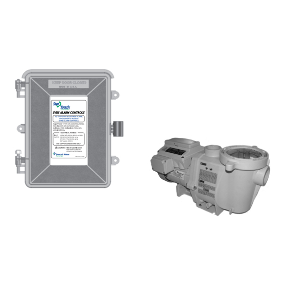
Safety vacuum release system (svrs) audible alarm for use with intelliflo vs+ svrs and intellipro vs+ svrs pumps
Hide thumbs
Also See for SunTouch:
- Installation and user manual (88 pages) ,
- Quick reference manual (2 pages) ,
- Installation and user manual (92 pages)
Table of Contents
Advertisement
Quick Links
Advertisement
Table of Contents

Related Manuals for Pentair SunTouch


Summary of Contents for Pentair SunTouch
- Page 1 ™ SunTouch Safety Vacuum Release System (SVRS) Audible Alarm ® (for use with IntelliFlo VS+ SVRS and IntelliPro ® VS+ SVRS pumps) Installation User’s Guide IMPORTANT SAFETY INSTRUCTIONS READ AND FOLLOW ALL INSTRUCTIONS SAVE THESE INSTRUCTIONS SVRS Audible Alarm Installation and User’s Guide...
- Page 2 Pentair Water Pool and Spa, Inc. Those names and brands may be the trademarks or registered trademarks of those parties or others.
-
Page 3: Table Of Contents
Contents Warnings and Important Safety Precautions ............ii Section 1: ........................1 Safety Vacuum Release System (SVRS) Audible Alarm Overview ....................1 Emergency Shut-Off switch (ESO3) Accessory ............1 IntelliFlo Operation Modes ..................1 Schedule Mode ......................1 Manual Mode ......................2 SVRS Power Center Control Panel ................ -
Page 4: Warnings And Important Safety Precautions
WARNINGS AND IMPORTANT SAFETY PRECAUTIONS SERIOUS BODILY INJURY OR DEATH CAN RESULT IF THIS PRODUCT IS NOT INSTALLED AND USED CORRECTLY. INSTALLERS, POOL OPERATORS AND POOL OWNERS MUST READ THESE WARNINGS AND ALL INSTRUCTIONS BEFORE USING THIS PRODUCT. The SVRS Alarm is intended for use in swimming pool applications and can only be used with The IntelliFlo®... - Page 5 WARNINGS AND IMPORTANT SAFETY PRECAUTIONS RISK OF ELECTRICAL SHOCK OR ELECTROCUTION: PUMPS REQUIRE HIGH VOLTAGE WHICH CAN SHOCK, BURN, OR CAUSE DEATH. BEFORE WORKING ON PUMP! Always disconnect power to the pool pump at the circuit breaker from the pump before servicing the pump.
- Page 6 WARNINGS AND IMPORTANT SAFETY PRECAUTIONS Two Speed Pump Controls Notice (Title 20 Compliance) Please read the following important Safety Instructions. When using two-speed pumps manufactured on or after January 1, 2008, the pump's default circulation speed MUST be set to the LOWEST SPEED, with a high speed override capability being for a temporary period not to exceed one normal cycle, or two hours, whichever is less.
- Page 7 WARNINGS AND IMPORTANT SAFETY PRECAUTIONS Only use a pumping system rated for the corresponding flow. FAILURE TO DO SO CAN RESULT IN HAIR OR BODY ENTRAPMENT WHICH CAN CAUSE SERIOUS PERSONAL INJURY OR DEATH. If in doubt about the rating of your system, consult a qualified pool service profes- sional.
- Page 8 WARNINGS AND IMPORTANT SAFETY PRECAUTIONS The Virginia Graeme Baker Pool and Spa Safety Act imposes certain new requirements on owners and operators of swimming pools and spas. Pools or spas constructed on or after December 20, 2008, shall utilize: (A) No submerged suction outlets, a gravity drainage system with ASME/ANSI cover(s), one or more unblockable outlets;...
-
Page 9: Section 1
Section 1 Safety Vacuum Release System (SVRS) Audible Alarm Overview The Safety Vacuum Release System (SVRS) audible alarm device is designed to be used with an IntelliFlo® VS+ SVRS pump or IntelliPro® VS+ SVRS pump. The pump is connected to the SVRS audible alarm circuit board via a 50 ft. two-conductor cable. -
Page 10: Manual Mode
• Each of the four pump speed buttons Manual mode (see page 9): are setup manually from the pump’s control panel. If an SVRS blockage event occurs in manual mode, check the suction outlets for a blockage then press the RESET/RESTART button to deactivate the alarm. -
Page 11: Main Menus
➂ MENU button: Use the Menu button to access the main menu items. There are five (5) menu items to select from. Press the MENU button to scroll though each of the five menu items. The main menu items are displayed MENU along with the menu number (1/5). -
Page 12: Service / Alarm Mode
Service / Alarm Mode Enter Service mode: Press the Menu button then Main Menu [1/5] Service / Alarm the Right arrow button to enter Service mode. Note: “Service” mode disables the Alarm mode and *Alarm Disabled* allows manual control of the pump. When the SVRS Service Mode Alarm is powered up and in “Service”... -
Page 13: Firmware Version
Displays the total SVRS event alarms. Total SVRS Event Count xxx0 Displays SVRS event alarms since last viewed. SVRS Error Since Last View xxx0 Displays total Communication alarms. Total Com Error Count xxx0 Communication alarms occur when the system is not communicating with the pump. -
Page 14: Troubleshooting (Status And System Alert Messages)
Troubleshooting (Status and System Alert Messages) The following alert messages may be displayed if a system error is detected. The pump is not running. Either the pump is in Pump is Not ‘manual” mode or is not scheduled to run at this time. Running To start the pump;... -
Page 15: Required Action For Svrs Blockage Event
Required Action for SVRS blockage Event (Schedule Mode, SVRS Auto Restart “Disabled”) IMPORTANT NOTE: Disabling the “SVRS Auto Restart” setting does not mean that the SVRS suction blockage feature is also being disabled. When the pump stops due to a SVRS blockage alarm, after the blockage has been removed, pressing the Reset/Restart button on the SVRS Alarm control panel will “Soft Prime”... - Page 16 Required Action for SVRS blockage Event (Schedule Mode, SVRS Auto Restart “Enabled”) Check for Drain System Normal SVRS Alarm !!! Blockage !!! 1520 RPM 340 Watt Blockage Alarm Pump in “Schedule” mode SVRS Audible Alarm ON (due to blockage) and SVRS “Auto Restart” (Display toggles two alert messages) feature “Enabled”...
-
Page 17: Required Action For Svrs Blockage Event
Required Action for SVRS blockage Event (Manual Mode, SVRS Auto Restart “Enabled/Disabled”) Pump in “Manual” mode and SVRS “Auto Restart” System Normal feature “Enabled or Disabled.” 1520 rpm 340 Watt Note: The pump will not restart automatically in “Soft Prime” mode. Pump Stopped and SVRS Audible Alarm ON due to blockage: Check for blockage in pool/spa. -
Page 18: Enable Or Disable The "Svrs Auto Restart" Setting
Enable or Disable the “SVRS Auto Restart” Setting To enable or disable the SVRS Auto Restart setting: 1. Check that the green power LED is on. 2. Press the Menu button. “Settings” is displayed. 3. Press the Select button. “Pump Address” is displayed. 4. -
Page 19: Intelliflo Vs+ Svrs And Intellipro Vs+ Svrs Pump Overview
IntelliFlo VS+ SVRS and IntelliPro VS+ SVRS Pump Overview The IntelliFlo VS+ SVRS and IntelliPro VS+ SVRS variable speed pump with the safety vacuum release system (SVRS) protection feature operates at a maximum system flow rate of up to 174 gallons per minute (GPM). The pump can operate from 1100 RPM to 3450 RPM with preset speeds of 1100, 1500, 2350 and 3110 RPM. -
Page 20: Intelliflo Pump Control Panel Buttons And Display Messages
Programming the IntelliFlo VS+ SVRS Pump By setting a start time and a stop time, Speeds 1-8 can be programmed to run a certain speed at a certain time of day. To run a scheduled pump speed, press the Start button (LED on). The LCD screen will display “Running Schedules” when it is ready to run a scheduled speed. - Page 21 15. Use the Left arrow button to move the cursor to the hour column if desired. 16. Press the Enter button to save the setting. 17. Press Down arrow. “Set Stop Time” is displayed 18. Press the Select button to change the stop time. 19.
-
Page 22: Section 2: Installation
Section 2 Installation Before installing the SVRS Alarm power center read the following guidelines: • Switch OFF AC power at the main circuit breaker panel, located at the house before high and low voltage connection to the power center. • AC power for the power center must be provided from the main circuit breaker panel located at the house. -
Page 23: Mounting The Svrs Power Center
Mounting the SVRS Alarm Power Center The SVRS Alarm Power Center can be mounted on a flat vertical surface, such as a wall or post. Note: Select a convenient location to mount the SVRS Alarm Power Center. DO NOT install the SVRS Power Center enclosure less five (5) feet from the pool/spa, filter and no further than 15 feet from the pool/spa valve. -
Page 24: Grounding And Bonding To The Svrs Power Center
Grounding and Bonding to the SVRS Alarm Power Center Connect a ground wire from the primary electrical panel to the SVRS Alarm power center ground bus bar. Also ground each piece of high voltage (120 VAC or 240 VAC) equipment that is connected to the SVRS Alarm power center relays. -
Page 25: High Voltage Transformer Wiring
High Voltage Transformer Wiring The high voltage wiring section is located inside the SVRS Alarm power center. The SVRS Alarm power center can be connected either to 120 VAC or 240 VAC. The SVRS Alarm power center should be wired to receive continuous power (connect directly to sub-panel). -
Page 26: Installing The Svrs Audible Alarm System
Installing the SVRS Audible Alarm System The following illustration shows the IntelliFlo VS+ SVRS pump connected to the SVRS Alarm circuit board using the pump’s RS-485 two-wire communication cable (provide with pump) and the SVRS audible alarm connected to the SVRS circuit board using a 50 ft. -
Page 27: Connection The Audible Alarm Plate
Install the alarm plate (See Figure 1) 1. Strip back the ends of 50 ft. cable conductors ¼ in. Loosen the two screws on the back of the alarm plate. Wrap each wire around each screw. Tight the screws to secure the wires. 2. -
Page 28: Connecting Intelliflo Pump To Svrs Power Center
Connecting IntelliFlo VS+ SVRS pump to the SVRS Alarm Power Center The IntelliFlo VS+ SVRS pump is connected to the SVRS Alarm circuit board center using the 50 ft. two-conductor communication cable (provided with pump). To connect the IntelliFlo pump communication cable (See Figure 2) 1. -
Page 29: Emergency Shut-Off Switch (Eso3) Accessory
ESO3’s alarm. ESO3 and IntelliFlo VS+SVRS SVRS alarm SUB PANEL power center CIRCUIT BREAKERS ESO3 Alarm EMERGENCY SHUT-OFF SunTouch PUSH TO ALARM SVRS Audible Alarm PULL TO RESET IntelliFlo VS+SVRS pump IntelliFlo VS+SVRS Low Voltage... -
Page 30: Mounting The Eso3
Mounting the ESO3 Select a convenient location to mount the Emergency Shut-Off switch (ESO3) near the SVRS audible alarm. Provide a UL-Listed double-gang electrical outlet box. The electrical box must be rated for outdoor/wet location use if the ESO3 is located outside. - Page 31 5. Connecting the ESO3 circuit board to the SVRS Alarm circuit board: Using the provided cable, connect AUX 3 on the SVRS alarm circuit board to one of the two-pin sockets located on the left side of the ESO3 circuit board as shown below. CLNR CLNR SVRS Alarm circuit board...
-
Page 32: Connecting The Eso3 Switch To The Circuit Board
Connecting the ESO3 Switch to the Circuit Board (see Figure 3) 7. Connecting the ESO3 switch: Route a two-wire cable (sold separately) through grommet located on the left-side of the SVRS Alarm power center, up into the low voltage raceway to the ESO3 switch circuit board. -
Page 33: Installing Auxiliary Relays
Installing Auxiliary Relays There can be a maximum of three standard auxiliary relays installed in the SVRS Alarm power center. Relays must be installed at the site. All SVRS Alarm high voltage double pole relays are rated at 3HP/30A at 240 VAC (1½ HP/30A at 120 VAC). - Page 34 Standard relay (Location 2): Position the relay (coil facing upward) in the relay compartment at about a 30° angle. Slide the tip of relay flange under head of the left-side screw. Rotate the relay downward to align the right-side flange with the screw hole. Using a 1/4 in nut driver, secure the relay in place with the retaining screw.
- Page 35 Notes SVRS Audible Alarm Installation and User’s Guide...
- Page 36 *521169* P/N 521169 Rev A SVRS Audible Alarm Installation and User’s Guide...