Siemens simatic et200sp Manual
Modular i/o system with ip20 degree of protection
Hide thumbs
Also See for simatic et200sp:
- System manual (320 pages) ,
- Manual (270 pages) ,
- Operating instructions manual (166 pages)
Table of Contents
Advertisement
Quick Links
Advertisement
Table of Contents

Related Manuals for Siemens simatic et200sp


Summary of Contents for Siemens simatic et200sp
- Page 2 ___________________ Analog input module Preface ___________________ Documentation guide ___________________ Product overview AI Energy Meter 480VAC ST ___________________ SIMATIC Wiring (6ES7134-6PA20-0BD0) ___________________ Configuration / address space ET 200SP ___________________ Analog input module Quick start AI Energy Meter 480VAC ST ___________________ Reading and processing measured values (6ES7134-6PA20-0BD0) ___________________...
- Page 3 Note the following: WARNING Siemens products may only be used for the applications described in the catalog and in the relevant technical documentation. If products and components from other manufacturers are used, these must be recommended or approved by Siemens. Proper transport, storage, installation, assembly, commissioning, operation and maintenance are required to ensure that the products operate safely and without any problems.
-
Page 4: Preface
Siemens recommends strongly that you regularly check for product updates. For the secure operation of Siemens products and solutions, it is necessary to take suitable preventive action (e.g. cell protection concept) and integrate each component into a holistic, state-of-the-art industrial security concept. -
Page 5: Table Of Contents
Table of contents Preface ..............................4 Documentation guide ..........................8 Product overview ..........................11 Area of application ........................11 Properties of the AI Energy Meter 480VAC ST ..............13 Wiring ..............................15 Terminal and block diagram ....................15 Connection examples ......................18 Current transformer selection data .................. - Page 6 Table of contents Operating hours counter ........................62 How the operating hours counter works ................62 Reset operating hours counters ..................... 63 8.2.1 Reset operating hours counters via user data ............... 63 8.2.2 Resetting operating hours counters via data record DS 143 ..........65 Limit monitoring ............................
- Page 7 Table of contents User data variants ..........................135 User data variants with 32 bytes input data / 12 bytes output data ........135 Measured value data records ......................155 Overview of all measured value data records ..............155 Measured value data record for base measurements (DS 142) .......... 156 Structure for energy counters (DS 143) ................
-
Page 8: Documentation Guide
ET 200SP distributed I/O system, e.g. diagnostics, communication, Web server, designing interference-free controllers. You can download the documentation free of charge from the Internet (http://w3.siemens.com/mcms/industrial-automation-systems-simatic/en/manual- overview/tech-doc-et200/Pages/Default.aspx). Changes and supplements to the manuals are documented in a Product Information. You can download the product information free of charge from the Internet (https://support.industry.siemens.com/cs/us/en/view/73021864). - Page 9 You need to register once to use the full functionality of "mySupport". You can find "mySupport" in the Internet (https://support.industry.siemens.com/My/ww/en). "mySupport" - Documentation In the Documentation area of "mySupport", you have the possibility to combine complete manuals or parts of them to make your own manual.
- Page 10 Solutions are shown in interplay with multiple components in the system - separated from the focus in individual products. You can find the application examples on the Internet (https://support.industry.siemens.com/sc/ww/en/sc/2054). TIA Selection Tool With the TIA Selection Tool, you can select, configure and order devices for Totally Integrated Automation (TIA).
-
Page 11: Product Overview
Product overview Area of application Introduction Energy efficiency is playing an increasingly important role in industry. Rising energy prices, increasing pressure to improve profitability and the growing awareness of climate protection are important factors for reducing energy costs and for introducing an energy data management system. - Page 12 Product overview 2.1 Area of application Measuring with AI Energy Meter 480VAC ST A typical supply network of a production plant is usually divided into three voltage ranges: ● The infeed of the entire plant ● The subdistribution, for example, to individual lines within the plant ●...
-
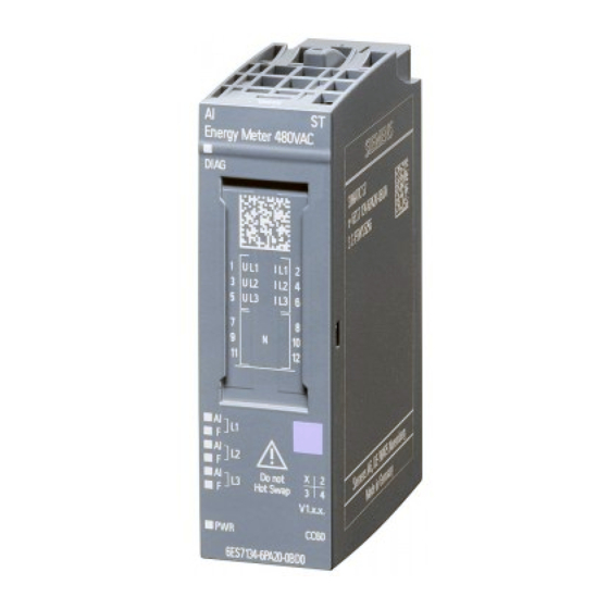
Page 13: Properties Of The Ai Energy Meter 480Vac St
Product overview 2.2 Properties of the AI Energy Meter 480VAC ST Properties of the AI Energy Meter 480VAC ST Article number 6ES7134-6PA20-0BD0 View of the module ① ⑥ Module type and name LED for supply voltage ② ⑦ LED for diagnostics Function class ③... - Page 14 ● BaseUnit Type D0 ● Labeling strips ● Reference identification label You can find additional information on the accessories in the ET 200SP distributed I/O system (http://support.automation.siemens.com/WW/view/es/58649293) system manual. Analog input module AI Energy Meter 480VAC ST (6ES7134-6PA20-0BD0) Manual, 12/2015, A5E36061895-AA...
-
Page 15: Wiring
Wiring Terminal and block diagram In an ET 200SP station, the AI Energy Meter 480VAC ST forms its own potential group together with its dark BaseUnit. General safety instructions WARNING Danger to life due to electric shock Touching live parts can lead to death or severe injuries. Before beginning any work deenergize the system and the Energy Meter and short-circuit installed transformers. - Page 16 Wiring 3.1 Terminal and block diagram Protecting the connection cables To protect the connection cables at U and U , make sure there is adequate cable protection, especially after cross-section transitions. If short-circuit resistance according to IEC 61439-1:2009 is ensured by the design, there is no need for separate cable protection for the AI Energy Meter 480VAC ST.
- Page 17 Wiring 3.1 Terminal and block diagram Usable BaseUnit The ET 200SP Distributed I/O System manual explains that a potential group always starts with a light BaseUnit. The AI Energy Meter 480VAC ST makes an exception in this case and only uses the dark BaseUnits type D0, 6ES7193-6BP00-0BD0. The BaseUnit is not in contact with the power bus and passes the potential through from the left to the right slot.
-
Page 18: Connection Examples
Wiring 3.2 Connection examples Connection examples The following figures show the connection of the Energy Meter for three-phase, two-phase and single-phase measurements. Note that the Energy Meter must always be connected via a current transformer. The use of voltage transformers is optional. Connection type Wiring diagram Comment... - Page 19 Wiring 3.2 Connection examples Connection type Wiring diagram Comment 3P4W1 Balanced load Three-phase measurement, Connection with one current and one voltage 4 wires transformer 2P3W Any load Two-phase measurement, 3 Connection with two current transformers conductors Energy Meter supplies the value "0" for all measured values of Phase 3 as well as for some cross-phase measured values.
- Page 20 Wiring 3.2 Connection examples Connection type Wiring diagram Comment 1P2W Measuring the load in an AC network with a current and a voltage converter Single-phase measurement, 2 conductors Energy Meter supplies the value "0" for all measured values of Phases 2 and 3 as well as for some cross-phase measured values.
-
Page 21: Current Transformer Selection Data
Wiring 3.3 Current transformer selection data Current transformer selection data Introduction Connection via a current transformer is always required for the current measurement. Use toroids with an accuracy class of 0.5, 1 or 3. Dimensioning of the current transformer The correct dimensioning of the current transformer is important for the following reasons: ●... - Page 22 Wiring 3.3 Current transformer selection data Maximum length of the connection cable To avoid overloading or damaging the current transformer, the burden Z specified on the data sheet of the current transformer (in VA) must not be exceeded. To prevent this being exceeded, the entire burden resistance (consisting of the resistance of the connection cable and the internal resistance of the AI Energy Meter 480VAC ST (see figure below) must be below a certain resistance value (depending on Z...
- Page 23 Wiring 3.3 Current transformer selection data Example: Usage of a current transformer 500/5 A You use a current transformer with a transmission ration of 500/5 A that has a rated burden of 5 VA according to the data sheet. The maximum primary current in the application amounts to 400 A. This means that the maximum secondary current I amounts to 4 A.
- Page 24 Wiring 3.3 Current transformer selection data Checking the ratio of burden load and power loss The rated burden of the transformer must be 1.5 to 2 times greater than the power loss in the connection circuit to ensure that the transformer is not overloaded and that the current limitation is ensured during a short-circuit.
-
Page 25: Configuration / Address Space
Configuration / address space Configuring Introduction To configure the AI Energy Meter 480VAC ST after connecting it, use configuration software such as STEP 7. In addition, you can also change numerous parameters of the AI Energy Meter 480VAC ST in RUN via the user program. Configuring You configure the AI Energy Meter 480VAC ST with: ●... -
Page 26: Selecting The Module Versions
Configuration / address space 4.2 Selecting the module versions Selecting the module versions Introduction The AI Energy Meter 480VAC ST has different module versions. During the configuration you use the selection of the module version to specify which measured values can be read. Each module version supplies quality information via the input user data. -
Page 27: Module Versions At Configuration With Step 7
Configuration / address space 4.2 Selecting the module versions 4.2.1 Module versions at configuration with STEP 7 Module versions with fixed user data assignment Module version User data Address space Comment 2 I / 2 Q No cyclic user data. 2-byte inputs Information about the structure of the 2 I / 2 Q 2-byte outputs... -
Page 28: Module Versions At Configuration With Gsd File
Configuration / address space 4.2 Selecting the module versions 4.2.2 Module versions at configuration with GSD file Module versions with fixed user data assignment Module ver- User data Address space Comment sion 2 I / 2 Q No cyclic user data. 2-byte inputs Information about the structure of the 2 I / 2 Q 2-byte outputs... -
Page 29: Changing Over The User Data Variant During Operation
Configuration / address space 4.2 Selecting the module versions 4.2.3 Changing over the user data variant during operation Introduction You change the user data variant in the output data of each user data variant in Byte 0. The following figure shows to which user data you can change over at various module versions during operation. -
Page 30: Recommendations For Selecting The Module Version
Configuration / address space 4.2 Selecting the module versions Result The user data variant is switched with the next cycle. Note Information about user data changeover The parameterized user data variant is set in the following cases: • A "0" is written in byte 0 in the output data of a user data variant. •... -
Page 31: Applicable Modules
Configuration / address space 4.3 Applicable modules Applicable modules Configuring with STEP 7 The following table shows with which controllers the different module versions can be configured with STEP 7. Table 4- 1 Module versions configured with STEP 7 Module version Controller 2 I / 2Q 32 I / 12 Q... - Page 32 Configuration / address space 4.3 Applicable modules Configuring with GSD file The following table shows with which controllers the different module versions can be configured using a GSD file. Table 4- 2 Module versions configuring with GSD file Module version Controller 2 I / 2Q 32 I / 12 Q...
-
Page 33: Quick Start
Quick start Introduction This section shows you how to read and view your first measured values on the Energy Meter 480 VAC ST in a particularly quick and easy way. Requirement You have already connected the Energy Meter to your network with one of the connection types shown in the section Wiring (Page 15). - Page 34 Quick start Result Once the Energy Meter has been switch on, it provides the measured values for the user data variant "Basic measurements" with the ID 254 or FE Read and check the measured values provided by the Energy Meter in the output data. The table below shows the structure of the user data variant, the measured variables and the data type of the measured values in STEP 7 (TIA Portal) that are stored in the 32 bytes of output data of the module.
-
Page 35: Reading And Processing Measured Values
32-bit measured values. Note the conversion can cause loss of accuracy. For more information, read FAQ: Processing 64-bit-floating-point numbers in S7-300/400 (https://support.industry.siemens.com/cs/ww/en/view/56600676) Validity of the measured values After turning on the supply voltage UL1, the first measured values are available after approximately 2 seconds. - Page 36 Reading and processing measured values 6.1 Basics for reading measured values Initial startup of the module After the first startup or restart of the module, the parameters are transferred to the module. You can preset a user data variant in the parameters of the hardware configuration. This remains in effect until a different user data variant is selected in the output data (byte 0).
-
Page 37: Quality Information
Reading and processing measured values 6.2 Quality information See also Reading measured values from user data cyclically (Page 40) Read measured value from a measured value data record (Page 42) Quality information Introduction The AI Energy Meter 480VAC ST supplies quality information about the measurement in a status word. - Page 38 Reading and processing measured values 6.2 Quality information Structure of the quality information Image 6-1 Quality information for low and high byte of the measured value ID 65503 Analog input module AI Energy Meter 480VAC ST (6ES7134-6PA20-0BD0) Manual, 12/2015, A5E36061895-AA...
- Page 39 Reading and processing measured values 6.2 Quality information Operating quadrant Image 6-2 Quadrant in the quality bits See also Module version "32 I / 12 Q" (Page 125) Analog input module AI Energy Meter 480VAC ST (6ES7134-6PA20-0BD0) Manual, 12/2015, A5E36061895-AA...
-
Page 40: Reading Measured Values From User Data Cyclically
Reading and processing measured values 6.3 Reading measured values from user data cyclically Reading measured values from user data cyclically Requirement ● STEP 7 is open. ● AI Energy Meter 480VAC ST is configured. Scaling of measured values in the user data Since the value range of 16-bit values is often smaller than the value range of the physical value, a scaling factor is supplied together with the basic value in the user data for the respective measured or calculated values. - Page 41 Reading and processing measured values 6.3 Reading measured values from user data cyclically Example The user data variant 254 (FE ) "Total power L1L2L3" is configured on the AI Energy Meter 480VAC ST. The measured value for "Current L1" should be read. Table 6- 1 Total power L1L2L3 Byte...
-
Page 42: Read Measured Value From A Measured Value Data Record
Reading and processing measured values 6.4 Read measured value from a measured value data record Read measured value from a measured value data record Introduction To read measured values of a measured value data record, use the RDREC instruction. The read values are stored in a PLC variable with user-defined data type (UDT). -
Page 43: Energy Counters
Energy counters How the energy meter works Introduction The AI Energy Meter 480VAC ST provides 42 energy counters that detect both line-based and phase-based energy values. ● Active energy (total, outflow, inflow) ● Reactive energy (total, outflow, inflow) ● Apparent energy (total) How energy recording works Based on the measured currents and voltages and the calculation cycle the Energy Meter calculates the active, reactive and apparent energy. - Page 44 Energy counters 7.1 How the energy meter works Changing properties in RUN You can change the following properties of energy counters in runtime: ● Enable / disable energy counter ● Reset energy counter ● Set initial values for the energy counter ●...
- Page 45 Energy counters 7.1 How the energy meter works Example The following figure shows the effect of initial value, reset and start/stop parameters with activated gating using the energy counter as an example: ① The counter is reset to the value specified in the configuration. The gate is closed. The counter does not count. ②...
-
Page 46: Configuring Counters
Energy counters 7.2 Configuring counters Configuring counters Overview You can configure the energy counters of the AI Energy Meter 480VAC ST as follows: ● Activate / Deactivate ● Start / stop counters using gate ● Set and reset start value Energy counter gate You have the option of starting and stopping the energy counter using the gate. -
Page 47: Evaluate Energy Counter And Overflow Counter
Energy counters 7.3 Evaluate energy counter and overflow counter Set and reset start value The counters can be set to their start value via the output data of each user data variant. With energy counters, you have to reset the bit of the energy counter in control byte 2 of the data record 143. -
Page 48: Resetting Energy Counters And Overflow Counters
Energy counters 7.4 Resetting energy counters and overflow counters Resetting energy counters and overflow counters Introduction At the beginning of a new work order, it may be useful to reset the energy and overflow counter of the Energy Meters Resetting here means setting the energy counters to their start values and resetting the overflow counters to 0. - Page 49 Energy counters 7.4 Resetting energy counters and overflow counters Procedure at module version with 12 bytes of output data 1. Set the category of the energy counters (active, reactive, apparent energy) to 1 in Control byte 2 via Bit 0 to 2 (in Byte 1, 6, 8 or 10 of the output data). 2.
-
Page 50: Resetting Energy Counters And Overflow Counters Via Data Record Ds 143
Energy counters 7.4 Resetting energy counters and overflow counters 7.4.2 Resetting energy counters and overflow counters via data record DS 143 Introduction At all the module versions you can reset the energy counters and their overflow counters via the data record DS 143. Resetting is possible for: ●... - Page 51 Energy counters 7.4 Resetting energy counters and overflow counters 3. In Control byte 1 of the DS 143 set Bit 7 for the moment of application of the start values of the desired energy counters: – Bit 7 to 0, if the start value are to be applied immediately after the transfer of the data record –...
-
Page 52: Example For Energy Counters And Overflow Counters Via Data Record Ds 143
Energy counters 7.4 Resetting energy counters and overflow counters Start values You specify the moment for the application of the start values in Control byte 1 via Bit 7. After the reset the energy counters count with the specified start values (default = 0) and the overflow counters begin again with 0. - Page 53 Energy counters 7.4 Resetting energy counters and overflow counters 2. Create a user-defined PLC data type and allocate the values of the data record in a DB or instance DB. Byte 0 and byte 1: Enter the value 01 in Byte 0 and the value 00 to Byte 1.
- Page 54 Energy counters 7.4 Resetting energy counters and overflow counters 3. Write the data record to the AI Energy Meter 480VAC ST module using the "WRREC" instruction. The input parameters must be allocated as follows: – REQ: A new write job is triggered if REQ = TRUE. –...
-
Page 55: Data Record For Energy Counter (Ds 143)
Energy counters 7.5 Data record for energy counter (DS 143) Data record for energy counter (DS 143) 7.5.1 Structure for energy counters (DS 143) Energy meter data record 143 for different actions The energy meter data record 143 includes all energy meters available on the module phase-by-phase. - Page 56 Energy counters 7.5 Data record for energy counter (DS 143) Byte Measured variable Data type Unit Value range Measured value ID 128...129 Overflow counter active energy inflow L1 UINT 61190 130..131 Overflow counter active energy outflow L1 UINT 61191 132...133 Overflow counter reactive energy inflow L1 UINT 61192...
- Page 57 Energy counters 7.5 Data record for energy counter (DS 143) Status information When data record 143 is read with the RDREC instruction, Bytes 2 to 7 supply phase- specific status information for energy counters, overflow counters and operating hours counters. The status information enables you can see which counters are returning their values in the data record 143.
- Page 58 Energy counters 7.5 Data record for energy counter (DS 143) Control information When data record 143 is written with the WRREC instruction, Bytes 2 to 7 are used as phase-specific control information for energy counters, overflow counters and operating hours counter. The length of the control information amounts to 2 bytes for each phase: ●...
- Page 59 Energy counters 7.5 Data record for energy counter (DS 143) Error while transferring the data record The module always checks all the values of the transferred data record. Only if all the values were transferred without errors does the module apply the values from the data record. The WRREC instruction for writing data records returns corresponding error codes when errors occur in the STATUS parameter.
-
Page 60: Structure Of The Control And Feedback Interface For Ds 143
Energy counters 7.5 Data record for energy counter (DS 143) 7.5.2 Structure of the control and feedback interface for DS 143 Introduction Bytes 2 to 7 of data record 143 form the phase-based control and feedback interface for the measured value data record of the energy counter. ●... - Page 61 Energy counters 7.5 Data record for energy counter (DS 143) Control information When data record 143 is written with the WRREC instruction, Bytes 2 to 7 are used as phase-specific control information for energy counters, overflow counters and operating hours counter. The length of the control information amounts to 2 bytes for each phase: ●...
-
Page 62: Operating Hours Counter
Operating hours counter How the operating hours counter works Introduction The AI Energy Meter 480VAC ST provides one operating hours counter for each phase, which counts the operating hours of the load connected to a phase when there is current greater than the configurable "Low limit for measuring current". -
Page 63: Reset Operating Hours Counters
Operating hours counter 8.2 Reset operating hours counters Reset operating hours counters Introduction At the beginning of a new work order, it may be useful to reset the operating hours counters of the Energy Meter. Resetting here means that the operating hours counters are reset to their start value. - Page 64 Operating hours counter 8.2 Reset operating hours counters Procedure at module version with 2 bytes of output data Set the reset bit (Bit 5) in Control byte 1 from 0 to 1 through an edge change. Image 8-2 Resetting the operating hours counters at module version with 2 bytes of output data Start values After the reset the operating hours counters count with the specified start values (default = 0).
-
Page 65: Resetting Operating Hours Counters Via Data Record Ds 143
Operating hours counter 8.2 Reset operating hours counters 8.2.2 Resetting operating hours counters via data record DS 143 Introduction At all the module versions you can reset the operating hours counters via the data record DS 143. Resetting is possible for: ●... -
Page 66: Limit Monitoring
Limit monitoring How limit monitoring works Introduction The AI Energy Meter 480VAC ST supports monitoring of parameterizable low or high limits for up to 16 analog measured or calculated variables. You can also define multiple limits for each measured or calculated variable, in order to define a high or low value range. -
Page 67: Influence Of Hysteresis And Delay Time On Limit Monitoring
Limit monitoring 9.2 Influence of hysteresis and delay time on limit monitoring Hardware interrupt at a limit violation The hardware interrupt provides the following information: ● Measured value ID of the monitored measured or calculated variable ● Number of the limit (0 = Limit 1. 15 = Limit 16) ●... - Page 68 Limit monitoring 9.2 Influence of hysteresis and delay time on limit monitoring The following figure shows the value-over-time for two measured values using the example of a high and low limit as well as the influence of hysteresis and delay time on the counting of the limit violations.
-
Page 69: Reset, Activate And Deactivate Counters For Limit Violation
Limit monitoring 9.3 Reset, activate and deactivate counters for limit violation Reset, activate and deactivate counters for limit violation Introduction At the beginning of a new work order, it may be useful to reset or also activate / deactivate the counters for limit violations of the Energy Meter. Resetting here means that the counters for limit violations are reset to 0. - Page 70 Limit monitoring 9.3 Reset, activate and deactivate counters for limit violation Activating / Deactivating counters for limit violations Activating / Deactivating of the counters for limit violations is only possible for module versions with 12 bytes of output data. Requirements: "Gate for limit value monitoring" was parameterized during configuration of the module using STEP 7 or by writing the data record DS 128.
-
Page 71: Minimum And Maximum Values
Minimum and maximum values 10.1 Minimum and maximum values Introduction The AI Energy Meter 480VAC ST determines the respective highest and lowest measured or calculated value for a series of measured and calculated values. The values are stored retentively in the module and can be read using measured value data records 144 and 145. Benefits Using the stored minimum and maximum values, for example, you can detect further irregularities in addition to limit monitoring. -
Page 72: Resetting Minimum And Maximum Values
Minimum and maximum values 10.2 Resetting minimum and maximum values Changing properties in RUN The following table shows the supported control information: Control information Default value Available in Reset saved maximum values Module version starting at 2 bytes of output data Reset saved minimum values Module version starting at 2 bytes of output data... - Page 73 Minimum and maximum values 10.2 Resetting minimum and maximum values Procedure at module version with 12 bytes of output data 1. Set the category of the measured values to 1 in Control byte 2 via Bit 0 to 4 in the output data.
-
Page 74: Phase-Based Measured Values
Phase-based measured values 11.1 Phase-based measured values Introduction The AI Energy Meter 480VAC ST makes the measured values of individual phases available. ● Through the user data variants – Phase-specific measurement Phase L1 with user data variants 154 (9A ) and 155 –... - Page 75 Phase-based measured values 11.1 Phase-based measured values Measured value data records Through the measured value data records DS 142, DS 147, DS 148 and DS 149 you can evaluate the following measured values for each phase of an AC / three-phase network: ●...
-
Page 76: Parameters
Parameters 12.1 Parameters Parameters of the AI Energy Meter 480VAC ST (DS 128, DS 129, DS 130) As a rule the AI Energy Meter 480VAC ST is already integrated in the hardware catalog of STEP 7 (TIA Portal) or STEP 7 V5.5 or higher. In this case STEP 7 (TIA Portal) or STEP 7 V5.5 or higher checks the parameterized properties for plausibility during designing. - Page 77 Parameters 12.1 Parameters Parameters Value range Default setting Reconfigura- Effective range with configuration tion in RUN software, e.g. STEP 7 (TIA Portal) GSD file GSD file PROFINET IO PROFIBUS DP Connection type 3P4W - 3 phases, Module Module Disabled • 4 conductors (only 1P2W, 1P2W - 1-phase...
- Page 78 Parameters 12.1 Parameters Parameters Value range Default setting Reconfigura- Effective range with configuration tion in RUN software, e.g. STEP 7 (TIA Portal) GSD file GSD file PROFINET IO PROFIBUS DP Full-scale value for No full-scale value Module No full-scale value - •...
- Page 79 Parameters 12.1 Parameters Parameters Value range Default setting Reconfigura- Effective range with configuration tion in RUN software, e.g. STEP 7 (TIA Portal) GSD file GSD file PROFINET IO PROFIBUS DP Enable gate of operat- Channel/phase • ing hours counter • Current transformer Channel/phase Module...
-
Page 80: Description Of Parameters
Parameters 12.2 Description of parameters 12.2 Description of parameters Hardware interrupt Enable the hardware interrupt for the entire module here. Diagnostics line voltage Activate the diagnostics line voltage here. If there is no voltage or too little voltage at L1, the message "No supply voltage at L1"... - Page 81 Parameters 12.2 Description of parameters Minimum and maximum value calculation Enable calculation of the minimum and maximum values here. The minimum and maximum value are calculated from the start of the measurement. The calculated values are stored retentively in the Energy Meter. Diagnostics overflow current The measured current is monitored after expiration of the "Tolerance time"...
- Page 82 Parameters 12.2 Description of parameters Diagnostics underflow voltage Line voltage (measuring range) is monitored for tolerance. A violation of the underflow triggers a diagnostic interrupt. Diagnostics low limit voltage Low limit for voltage is monitored. A violation of the low limit triggers a diagnostic interrupt. Diagnostics overflow cumulative values A cumulative overflow in the calculated variables is displayed.
- Page 83 Parameters 12.2 Description of parameters Operating hours counter Enable the operating hours counter here. The counting starts from a programmable minimum current value. The counter can be reset or pre-defined using data record or output bit. Enable gate of operating hours counter Enable the gate for the operating hours counter here.
- Page 84 Parameters 12.2 Description of parameters Limit monitoring Enable the monitoring of the limit for a freely definable measured value here. Limit violations are counted and the count values stored retentively. Measured value ID for limit Enter the ID of a measured value that you want to use for limit monitoring. Limit gate via DQ Enable the gate via DQ here.
-
Page 85: Interrupts/Diagnostic Alarms
Interrupts/diagnostic alarms 13.1 Status and error display LED display ① DIAG (green/red) ② Error (red) ③ PWR (green) ④ Status (green) Image 13-1 LED display Analog input module AI Energy Meter 480VAC ST (6ES7134-6PA20-0BD0) Manual, 12/2015, A5E36061895-AA... - Page 86 Interrupts/diagnostic alarms 13.1 Status and error display Meaning of the LED displays The following table explains the meaning of the status and error displays. Remedial measures for diagnostic alarms can be found in the section Diagnostic alarms (Page 88). DIAG LED Table 13- 1 Meaning of the DIAG LED DIAG...
-
Page 87: Interrupts
Interrupts/diagnostic alarms 13.2 Interrupts 13.2 Interrupts The AI Energy Meter ST analog input module supports hardware and diagnostic interrupts. 13.2.1 Hardware interrupts Hardware interrupts The module generates a hardware interrupt at the following events: ● Violation of low limit 1 to 16 ●... -
Page 88: Diagnostics Interrupt
Interrupts/diagnostic alarms 13.3 Diagnostic alarms 13.2.2 Diagnostics interrupt Diagnostic interrupt The module generates a diagnostic error interrupt at the following events: ● Channel is temporarily unavailable ● Hardware interrupt lost ● Error ● Supply voltage missing ● Parameter assignment error ●... - Page 89 Interrupts/diagnostic alarms 13.3 Diagnostic alarms Table 13- 6 Error types Diagnostic message Error code Meaning Solution Undervoltage Line voltage (measuring range) is moni- Observe the line voltage range tored for tolerance. Violation leads to volt- Overvoltage age overflow/underflow Overload The measured current is monitored after Observe the current range expiration of the "Tolerance time"...
-
Page 90: Diagnostics Response
Interrupts/diagnostic alarms 13.4 Diagnostics response 13.4 Diagnostics response Diagnostics response This section describes the response of the AI Energy Meter 480VAC ST when diagnostics information is reported. Measured values in the case of diagnostics Even in the case of diagnostics, measured values continue to be displayed as long as they can still be acquired. - Page 91 Interrupts/diagnostic alarms 13.4 Diagnostics response Loss of the supply voltage At a loss of supply voltage at U (phase 1), all measurements are interrupted. After the supply voltage is restored, the AI Energy Meter 480VAC ST operates again with the configuration / parameter assignment stored in the CPU.
-
Page 92: Technical Specifications
Technical specifications 14.1 Technical specifications Technical specifications of the AI Energy Meter 480VAC ST 6ES7134-6PA20-0BD0 6ES7134-6PA20-0BD0 General information Product type designation AI Energy Meter 480VAC ST Usable BaseUnits BU type D0, BU20-P12+A0+0B Color code for module-specific color identification CC00 label Product function Voltage measurement Voltage measurement with voltage transformer... - Page 93 Technical specifications 14.1 Technical specifications 6ES7134-6PA20-0BD0 Line frequency Valid range, low limit 47 Hz Valid range, high limit 63 Hz Power loss Power loss, typ. 0.6 W Address area Address space per module Address space per module, max. 256 bytes; for input and output data each Hardware configuration Automatic code Mechanical coding element...
- Page 94 Technical specifications 14.1 Technical specifications 6ES7134-6PA20-0BD0 Measuring range 45 Hz Frequency measurement, min. • 65 Hz Frequency measurement, max. • Measuring inputs for voltage 277 V Measurable line voltage between phase and • neutral conductor 480 V Measurable line voltage between the line con- •...
- Page 95 In accordance with EN 60079-15 (Electrical apparatus for potentially explosive atmospheres; Type of protection "n") and EN 60079-0 (Electrical apparatus for potentially explosive gas atmospheres - Part 0: General Requirements) Dimension drawing See ET 200SP BaseUnits (http://support.automation.siemens.com/WW/view/en/59753521) manual Analog input module AI Energy Meter 480VAC ST (6ES7134-6PA20-0BD0) Manual, 12/2015, A5E36061895-AA...
- Page 96 Technical specifications 14.1 Technical specifications Analog input module AI Energy Meter 480VAC ST (6ES7134-6PA20-0BD0) Manual, 12/2015, A5E36061895-AA...
-
Page 97: Parameter Data Records
Parameter data records Configuration via parameter data records The parameter data records of the module have an identical structure, regardless of whether you configure the module with PROFIBUS DP or PROFINET IO. Parameter assignment in the user program You can reassign the module parameters in RUN mode, for example change the diagnostics behavior, define new limits or configure a modified user data mapping. -
Page 98: Structure Of The Parameter Data Record 128 For The Entire Module
Parameter data records A.2 Structure of the parameter data record 128 for the entire module Structure of the parameter data record 128 for the entire module Structure of data record 128 Image A-1 Parameter data record 128 Header information The figure below shows the structure of the header information. Image A-2 Header information Analog input module AI Energy Meter 480VAC ST (6ES7134-6PA20-0BD0) - Page 99 Parameter data records A.2 Structure of the parameter data record 128 for the entire module Module header information The figure below shows the structure of the header information for a module. Image A-3 Module header information Analog input module AI Energy Meter 480VAC ST (6ES7134-6PA20-0BD0) Manual, 12/2015, A5E36061895-AA...
- Page 100 Parameter data records A.2 Structure of the parameter data record 128 for the entire module Module parameter block The figure below shows the structure of the module parameter block. Enable a parameter by setting the corresponding bit to "1". Analog input module AI Energy Meter 480VAC ST (6ES7134-6PA20-0BD0) Manual, 12/2015, A5E36061895-AA...
- Page 101 Parameter data records A.2 Structure of the parameter data record 128 for the entire module Image A-4 Module parameter block You can find the user data variant in the section Overview of the user data variants (Page 135). Channel header information The following figure shows the structure of the header information for a channel.
- Page 102 Parameter data records A.2 Structure of the parameter data record 128 for the entire module Channel parameter block The figure below shows the structure of the channel parameter block. Enable a parameter by setting the corresponding bit to "1". Analog input module AI Energy Meter 480VAC ST (6ES7134-6PA20-0BD0) Manual, 12/2015, A5E36061895-AA...
- Page 103 Parameter data records A.2 Structure of the parameter data record 128 for the entire module Analog input module AI Energy Meter 480VAC ST (6ES7134-6PA20-0BD0) Manual, 12/2015, A5E36061895-AA...
- Page 104 Parameter data records A.2 Structure of the parameter data record 128 for the entire module Image A-6 Channel parameter block Error while transferring the data record The module always checks all the values of the transferred data record. Only if all the values were transferred without errors does the module apply the values from the data record.
- Page 105 Parameter data records A.2 Structure of the parameter data record 128 for the entire module Error code in STATUS parame- Meaning Solution (hexadecimal) Byte 0 Byte 1 Byte 2 Byte 3 Parameter for user data variant not possi- Check Byte 9. Select a different user data ble.
-
Page 106: Structure Of The Parameter Data Record 129 For Limit Monitoring
Parameter data records A.3 Structure of the parameter data record 129 for limit monitoring Structure of the parameter data record 129 for limit monitoring Structure of data record 129 Image A-7 Structure of data record 129 Header information The figure below shows the structure of the header information. Image A-8 Header information DS 129 Analog input module AI Energy Meter 480VAC ST (6ES7134-6PA20-0BD0) - Page 107 Parameter data records A.3 Structure of the parameter data record 129 for limit monitoring Limit parameter block The following diagram shows the structure of the parameter blocks for limit monitoring. Analog input module AI Energy Meter 480VAC ST (6ES7134-6PA20-0BD0) Manual, 12/2015, A5E36061895-AA...
- Page 108 Parameter data records A.3 Structure of the parameter data record 129 for limit monitoring Image A-9 Limit parameter data block Analog input module AI Energy Meter 480VAC ST (6ES7134-6PA20-0BD0) Manual, 12/2015, A5E36061895-AA...
- Page 109 Parameter data records A.3 Structure of the parameter data record 129 for limit monitoring Error while transferring the data record The module always checks all the values of the transferred data record. Only if all the values were transferred without errors does the module apply the values from the data record. The WRREC instruction for writing data records returns corresponding error codes when errors occur in the STATUS parameter.
-
Page 110: Structure Of The Parameter Data Record 130 For User-Data Mapping
Parameter data records A.4 Structure of the parameter data record 130 for user-data mapping Structure of the parameter data record 130 for user-data mapping Structure of data record 130 Image A-10 Structure of data record 130 Header information The figure below shows the structure of the header information. Image A-11 Header information DS 130 Analog input module AI Energy Meter 480VAC ST (6ES7134-6PA20-0BD0) - Page 111 Parameter data records A.4 Structure of the parameter data record 130 for user-data mapping Parameter block for user data mapping The following diagram shows the structure of the parameter blocks for user data mapping. Image A-12 Parameter block for user data mapping Analog input module AI Energy Meter 480VAC ST (6ES7134-6PA20-0BD0) Manual, 12/2015, A5E36061895-AA...
- Page 112 Parameter data records A.4 Structure of the parameter data record 130 for user-data mapping Error while transferring the data record The module always checks all the values of the transferred data record. Only if all the values were transferred without errors does the module apply the values from the data record. The WRREC instruction for writing data records returns corresponding error codes when errors occur in the STATUS parameter.
-
Page 113: Measured Variables
Measured variables Measured variables for data records and user data The following table provides an overview of all measured variables that are used in the data records and user data. Note that the format and unit differ in the evaluation of records and user data. Table B- 1 Measured variables for data records and user data Meas-... - Page 114 Measured variables Meas- Measured variables Data Unit Value range Connection type ured type 1P2W 3x1P2W 2P3W 3P4W 3P4W1 value ID Frequency REAL 45.0 ... 65.0 ✓ ✓ ✓ ✓ ✓ Total apparent power REAL -3.0 x 10 … ✓ ✓ ✓...
- Page 115 Measured variables Meas- Measured variables Data Unit Value range Connection type ured type 1P2W 3x1P2W 2P3W 3P4W 3P4W1 value ID Max. total apparent REAL -3.0 x 10 … ✓ ✓ ✓ ✓ ✓ power +3.0 x 10 Max. total active power REAL -3.0 x 10 …...
- Page 116 Measured variables Meas- Measured variables Data Unit Value range Connection type ured type 1P2W 3x1P2W 2P3W 3P4W 3P4W1 value ID Min. total power factor REAL 0.0 ... 1.0 ✓ ✓ ✓ ✓ ✓ Total active energy in- REAL 0.0 ... 3.4 x 10 ✓...
- Page 117 Measured variables Meas- Measured variables Data Unit Value range Connection type ured type 1P2W 3x1P2W 2P3W 3P4W 3P4W1 value ID 61180 Active energy inflow L1 LREAL 0.0 ... 1.8 x 10 ✓ ✓ ✓ ✓ ✓ 61181 Active energy outflow LREAL 0.0 ...
- Page 118 Measured variables Meas- Measured variables Data Unit Value range Connection type ured type 1P2W 3x1P2W 2P3W 3P4W 3P4W1 value ID 61221 Active energy outflow LREAL 0.0 ... 1.8 x 10 ✓ ✓ ✓ 61222 Reactive energy inflow LREAL varh 0.0 ... 1.8 x 10 ✓...
- Page 119 Measured variables Meas- Measured variables Data Unit Value range Connection type ured type 1P2W 3x1P2W 2P3W 3P4W 3P4W1 value ID 62311 Active energy outflow UDINT 0 ... 4294967295 ✓ ✓ ✓ 62312 Reactive energy inflow UDINT Varh 0 ... 4294967295 ✓...
- Page 120 Measured variables Meas- Measured variables Data Unit Value range Connection type ured type 1P2W 3x1P2W 2P3W 3P4W 3P4W1 value ID 65517 Counter limit violation UDINT 0 ... 4294967295 ✓ ✓ ✓ ✓ ✓ 65518 Counter limit violation UDINT 0 ... 4294967295 ✓...
- Page 121 Measured variables Meas- Measured variables Data Unit Value range Connection type ured type 1P2W 3x1P2W 2P3W 3P4W 3P4W1 value ID 66035 Total active power -27648 ... 27648 ✓ ✓ ✓ ✓ ✓ L1L2L3 66036 Total reactive power 1 var -27648 ... 27648 ✓...
-
Page 122: Module Versions
Module versions Module version "2 I / 2 Q" User data of the module The module has 2 bytes of input user data and 2 bytes of output user data for status and control information. At this module version measured variables can be read solely via measured value data records (no measured variables can be evaluated via user data). - Page 123 Module versions C.1 Module version "2 I / 2 Q" Allocation of the input user data Image C-1 Allocation of the status bytes in the input user data (2 bytes) Structure of output user data The structure of the output user data is fixed. Table C- 2 Structure of output user data (2 bytes) Byte...
- Page 124 Module versions C.1 Module version "2 I / 2 Q" Assignment of the output user data Via the output user data you control for all phases ● Resetting for all minimum values, maximum values, limits, operating hours counter and energy counters. ●...
-
Page 125: Module Version "32 I / 12 Q
Module versions C.2 Module version "32 I / 12 Q" Module version "32 I / 12 Q" User data of the module The module occupies 32 bytes of input user data and 12 bytes of output user data. Of these the module uses 2 bytes input data for status information and 12 bytes output data for control information. - Page 126 Module versions C.2 Module version "32 I / 12 Q" Allocation of the input user data You can change the measured variables during operation. You can choose between different user data variants. Image C-3 Assignment of the input user data (32 bytes) Analog input module AI Energy Meter 480VAC ST (6ES7134-6PA20-0BD0) Manual, 12/2015, A5E36061895-AA...
- Page 127 Module versions C.2 Module version "32 I / 12 Q" Structure of output user data The structure of the output user data is fixed and is the same at all the selectable user data variants. Via the output user data you control globally or phase-specifically ●...
- Page 128 Module versions C.2 Module version "32 I / 12 Q" Control bytes for all three phases Image C-5 Allocation of the control bytes for all three phases (bytes 1 and 2) Analog input module AI Energy Meter 480VAC ST (6ES7134-6PA20-0BD0) Manual, 12/2015, A5E36061895-AA...
- Page 129 Module versions C.2 Module version "32 I / 12 Q" Control bytes for limit monitoring Image C-6 Allocation of the control bytes for limit monitoring (bytes 3 to 5) Analog input module AI Energy Meter 480VAC ST (6ES7134-6PA20-0BD0) Manual, 12/2015, A5E36061895-AA...
- Page 130 Module versions C.2 Module version "32 I / 12 Q" Control bytes for each individual phase Image C-7 Allocation of the control bytes for each individual phase (bytes 6 to 11) Analog input module AI Energy Meter 480VAC ST (6ES7134-6PA20-0BD0) Manual, 12/2015, A5E36061895-AA...
-
Page 131: User-Specific" Module Version
Module versions C.3 "User-specific" module version "User-specific" module version User data of the module The module occupies between 16 and 256 bytes of input user data and 12 bytes of output user data. Of these the module uses 2 bytes input data for status information and 12 bytes output data for control information. - Page 132 Module versions C.3 "User-specific" module version Allocation of the input user data You can change the measured variables during operation. You can choose between different user data variants. The allocation of the status information in Byte 0 and 1 corresponds to the module version 32 I / 12 Q, see appendix Module version "32 I / 12 Q"...
-
Page 133: Module Version "Ee@Industry Measurement Data Profile E0 / E1 / E2 / E3
Module versions C.4 Module version "EE@Industry measurement data profile E0 / E1 / E2 / E3" Module version "EE@Industry measurement data profile E0 / E1 / E2 / E3" User data of the module The four versions according to EE@Industry use between 4 and 104 bytes of input user data and 12 bytes of output user data. - Page 134 Module versions C.4 Module version "EE@Industry measurement data profile E0 / E1 / E2 / E3" Table C- 9 Measurement data profile E3 Byte Allocation Data type Unit Value range Measured value ID 0...3 Active power L1 REAL -3.0 x 10 ...
-
Page 135: User Data Variants
User data variants User data variants with 32 bytes input data / 12 bytes output data User data 30 bytes are available for transferring the measured values in a cycle at the module version 32 I / 12 Q. Therefore this module version supports dynamic switching between 22 preconfigured user data variants that contain a specific selection of measured values. - Page 136 User data variants D.1 User data variants with 32 bytes input data / 12 bytes output data Total power L1L2L3 (ID 254 or FE Table D- 2 Total power L1L2L3 Byte Allocation Data type Unit Value range Measured value ID User data variant BYTE 254 (FE...
- Page 137 User data variants D.1 User data variants with 32 bytes input data / 12 bytes output data Active power L1L2L3 (ID 253 or FD Table D- 3 Active power L1L2L3 Byte Allocation Data type Unit Value range Measured value ID User data variant BYTE 253 (FD...
- Page 138 User data variants D.1 User data variants with 32 bytes input data / 12 bytes output data Reactive power L1L2L3 (ID 252 or FC Table D- 4 Reactive power L1L2L3 Byte Allocation Data type Unit Value range Measured value ID User data variant BYTE 252 (FC...
- Page 139 User data variants D.1 User data variants with 32 bytes input data / 12 bytes output data Apparent power L1L2L3 (ID 251 or FB Table D- 5 Apparent power L1L2L3 Byte Allocation Data type Unit Value range Measured value ID User data variant BYTE 251 (FB...
- Page 140 User data variants D.1 User data variants with 32 bytes input data / 12 bytes output data Basic measured values L1L2L3 (ID 250 or FA Table D- 6 Basic measured values L1L2L3 Byte Allocation Data type Unit Value range Measured value ID User data variant BYTE...
- Page 141 User data variants D.1 User data variants with 32 bytes input data / 12 bytes output data Total energy L1L2L3 (ID 249 or F9 Table D- 7 Total energy L1L2L3 Byte Allocation Data type Unit Value range Measured value ID User data variant BYTE 249 (F9...
- Page 142 User data variants D.1 User data variants with 32 bytes input data / 12 bytes output data Energy L1 (ID 248 or F8 Table D- 8 Energy L1 Byte Allocation Data type Unit Value range Measured value ID User data variant BYTE 248 (F8 Quality information = QQ...
- Page 143 User data variants D.1 User data variants with 32 bytes input data / 12 bytes output data Energy L2 (ID 247 or F7 Table D- 9 Energy L2 Byte Allocation Data type Unit Value range Measured value ID User data variant BYTE 247 (F7 Quality information = QQ...
- Page 144 User data variants D.1 User data variants with 32 bytes input data / 12 bytes output data Energy L3 (ID 246 or F6 Table D- 10 Energy L3 Byte Allocation Data type Unit Value range Measured value ID User data variant BYTE 246 (F6 Quality information = QQ...
- Page 145 User data variants D.1 User data variants with 32 bytes input data / 12 bytes output data Basic variables quality values three-phase measurement (ID 240 or F0 Table D- 12 Basic variables quality values three-phase measurement Byte Allocation Data type Unit Value range Meas-...
- Page 146 User data variants D.1 User data variants with 32 bytes input data / 12 bytes output data Basic variables energy counter measurement (periodic) overflow counter (ID 239 or EF Table D- 13 Basic variables energy counter measurement (periodic) overflow counter Byte Allocation Data type...
- Page 147 User data variants D.1 User data variants with 32 bytes input data / 12 bytes output data Basic variables measurement data profile (ID 227 or E3 Table D- 14 Basic variables measurement data profile Energy E3 Byte Allocation Data type Unit Value range Measured...
- Page 148 User data variants D.1 User data variants with 32 bytes input data / 12 bytes output data Basic variables measurement data profile (ID 226 or E2 Table D- 15 Basic variables measurement data profile Energy E2 Byte Allocation Data type Unit Value range Meas-...
- Page 149 User data variants D.1 User data variants with 32 bytes input data / 12 bytes output data Basic variables phase-specific measurement (ID 159 or 9F Table D- 18 Basic variables phase-specific measurement L1 Byte Allocation Data type Unit Value range Measured value ID User data variant...
- Page 150 User data variants D.1 User data variants with 32 bytes input data / 12 bytes output data Basic variables phase-specific measurement (ID 158 or 9E Table D- 19 Basic variables phase-specific measurement L1a Byte Allocation Data type Unit Value range Measured value ID User data variant...
- Page 151 User data variants D.1 User data variants with 32 bytes input data / 12 bytes output data Basic variables phase-specific measurement (ID 157 or 9D Table D- 20 Basic variables phase-specific measurement L2 Byte Allocation Data type Unit Value range Measured value ID User data variant...
- Page 152 User data variants D.1 User data variants with 32 bytes input data / 12 bytes output data Basic variables phase-specific measurement (ID 156 or 9C Table D- 21 Basic variables phase-specific measurement L2a Byte Allocation Data type Unit Value range Measured value ID User data variant...
- Page 153 User data variants D.1 User data variants with 32 bytes input data / 12 bytes output data Basic variables phase-specific measurement (ID 155 or 9B Table D- 22 Basic variables phase-specific measurement L3 Byte Allocation Data type Unit Value range Measured value ID User data variant...
- Page 154 User data variants D.1 User data variants with 32 bytes input data / 12 bytes output data Basic variables phase-specific measurement (ID 154 or 9A Table D- 23 Basic variables phase-specific measurement L3a Byte Allocation Data type Unit Value range Measured value ID User data variant...
-
Page 155: Measured Value Data Records
Measured value data records Overview of all measured value data records Energy Meter 480VAC ST writes the measured values in several data records that you can read acyclically using the RDREC instruction in the user program. The following tables show the structure of the individual data records: ●... -
Page 156: Measured Value Data Record For Base Measurements (Ds 142)
Measured value data records E.2 Measured value data record for base measurements (DS 142) Measured value data record for base measurements (DS 142) Measured variables of the module The following table provides an overview of all the measured variables that data record 142 supplies. - Page 157 Measured value data records E.2 Measured value data record for base measurements (DS 142) Byte Measured variable Data type Unit Value range Measured value ID 110...113 Total active power L1L2L3 REAL -3.0 x 10 … +3.0 x 10 114...117 Phase angle L1 REAL °...
- Page 158 For a description of the conversion of the 64-bit floating-point numbers (data type LREAL) into 32-bit floating-point numbers (data type REAL) please refer to the Internet (http://support.automation.siemens.com/WW/view/en/56600676). Analog input module AI Energy Meter 480VAC ST (6ES7134-6PA20-0BD0) Manual, 12/2015, A5E36061895-AA...
-
Page 159: Structure For Energy Counters (Ds 143)
Measured value data records E.3 Structure for energy counters (DS 143) Structure for energy counters (DS 143) Energy meter data record 143 for different actions The energy meter data record 143 includes all energy meters available on the module phase-by-phase. The data record can be used for different actions: ●... - Page 160 Measured value data records E.3 Structure for energy counters (DS 143) Byte Measured variable Data Unit Value range Meas- type ured value ID 128...129 Overflow counter active energy inflow L1 UINT 61190 130..131 Overflow counter active energy outflow L1 UINT 61191 132...133 Overflow counter reactive energy inflow L1...
- Page 161 Measured value data records E.3 Structure for energy counters (DS 143) Status information When data record 143 is read with the RDREC instruction, Bytes 2 to 7 supply phase- specific status information for energy counters, overflow counters and operating hours counters.
- Page 162 Measured value data records E.3 Structure for energy counters (DS 143) Control information When data record 143 is written with the WRREC instruction, Bytes 2 to 7 are used as phase-specific control information for energy counters, overflow counters and operating hours counter.
- Page 163 Measured value data records E.3 Structure for energy counters (DS 143) Error while transferring the data record The module always checks all the values of the transferred data record. Only if all the values were transferred without errors does the module apply the values from the data record. The WRREC instruction for writing data records returns corresponding error codes when errors occur in the STATUS parameter.
-
Page 164: Measured Value Data Record For Maximum Values (Ds 144)
Measured value data records E.4 Measured value data record for maximum values (DS 144) Measured value data record for maximum values (DS 144) Measured variables of the module The largest values ever measured or calculated from the time AI Energy Meter 480VAC ST was started are stored in this data record. -
Page 165: Measured Value Data Record For Minimum Values (Ds 145)
Measured value data records E.5 Measured value data record for minimum values (DS 145) Byte Measured variable Format Unit Default Measured Connection type value ID 1P2W 3x1P2W 2P3W 3P4W 3P4W1 90...93 Max. total apparent REAL ✓ ✓ ✓ ✓ ✓ power 94...97 Max. -
Page 166: Measured Value Data Record For Phase-Based Measured Values L1 (Ds 147)
Measured value data records E.6 Measured value data record for phase-based measured values L1 (DS 147) Byte Measured variable Format Unit Default Measured Connection type value ID 1P2W 3x1P2W 2P3W 3P4W 3P4W1 66...69 Min. reactive power REAL +3.0 x 10 ✓... -
Page 167: Measured Value Data Record For Phase-Based Measured Values L2 (Ds 148)
Measured value data records E.7 Measured value data record for phase-based measured values L2 (DS 148) Byte Measured varia- Format Unit Value range Meas- Connection type ured 1P2W 3x1P2W 2P3W 3P4W 3P4W1 value 28...31 Phase angle L1 REAL ° 0.0 ... 360.0 61178 ✓... - Page 168 Measured value data records E.7 Measured value data record for phase-based measured values L2 (DS 148) Byte Measured varia- Format Unit Value range Meas- Connection type ured 1P2W 3x1P2W 2P3W 3P4W 3P4W1 value 2...3 Qualifier L2 WORD 0b 00 00 00 00 65501 ✓...
-
Page 169: Measured Value Data Record For Phase-Based Measured Values L3 (Ds 149)
Measured value data records E.8 Measured value data record for phase-based measured values L3 (DS 149) Measured value data record for phase-based measured values L3 (DS 149) Measured variables of the module (DS 149) Byte Measured variable For- Unit Value range Meas- Connection type ured... -
Page 170: Measured Value Data Record For Advanced Measurement And Status Values (Ds 150)
Measured value data records E.9 Measured value data record for advanced measurement and status values (DS 150) Byte Measured variable For- Unit Value range Meas- Connection type ured 1P2W 3x1P2W 2P3W 3P4W 3P4W1 value 80...83 Min. voltage UL1-N REA 0.0 ... 1000000.0 ✓... - Page 171 Measured value data records E.9 Measured value data record for advanced measurement and status values (DS 150) Byte Measured variable Format Unit Value range Measured value ID 62...65 Counter limit violation GW 11 UDINT 0 ... 4294967296 65520 66...69 Counter limit violation GW 12 UDINT 0 ...
-
Page 172: Tips And Tricks
On the basis of an application example we show you how the measured values of the AI Energy Meter can be processed further and visualized. You can find this application example on the Internet (http://support.automation.siemens.com/WW/view/en/86299299) IT network You must create an artificial N-conductor (for example, by means of a 1:1 voltage transformer) in IT networks due to the missing neutral conductor.