Lexmark CX725 Service Manual
Hide thumbs
Also See for CX725:
- User manual (157 pages) ,
- User manual (273 pages) ,
- User manual (182 pages)
Table of Contents
Advertisement
Quick Links
Download this manual
See also:
User Manual
Advertisement
Table of Contents

Related Manuals for Lexmark CX725


Summary of Contents for Lexmark CX725
-
Page 1: Service Manual
CX725 and XC4150 7528-576, -578, -598 Service Manual • Start diagnostics • Maintenance • Safety and notices • Trademarks • Index January 25, 2016 www.lexmark.com P/N 12G3423... -
Page 2: Product Information
Trademarks Lexmark and the Lexmark logo are trademarks of Lexmark International, Inc., registered in the United States and/or other countries. PCL® is a registered trademark of the Hewlett-Packard Company. PCL is Hewlett-Packard Company’s designation of a set of printer commands (language) and functions included in its printer products. -
Page 3: Table Of Contents
7528 Table of contents Product information..................2 Edition notice....................2 Notices and safety information..............13 Laser notice................................13 Avis relatif à l'utilisation du laser........................13 Notificació del làser............................13 Aviso de láser..............................13 Aviso sobre laser..............................14 Avvertenze sui prodotti laser.......................... 14 Laserinformatie..............................14 Lasererklæring.............................. - Page 4 7528 安全信息........................... 21 安全情報........................... 22 安全資訊........................... 22 Preface......................23 Conventions................................23 General caution statements........................... 23 General information................... 25 Finding the serial number..........................25 Paper and specialty media guide......................... 26 Paper guidelines................................26 Using specialty media ..............................27 Supported paper sizes, types, and weights ......................29 Data security notice............................
- Page 5 7528 Light print check ................................59 Skewed print service check ............................. 62 Fixing scan quality issues..........................64 Dark image quality (using the ADF or scanner) check ..................64 Vertical lines (process direction using the ADF) check ..................65 Spots (using the flatbed scanner) check ....................... 66 ADF skew check ................................
- Page 6 7528 Region mismatch service check..........................173 Maintenance kit service check ..........................174 Cartridge or photoconductor error service check..................... 174 Mismatched paper size service check ......................... 175 Insufficient memory service check ........................176 Complex page service check..........................176 Flash memory failure service check........................177 Insufficient flash memory service check ......................
- Page 7 7528 Network service check ............................265 Toner meter cycle (TMC) card service check.....................268 USB service check ..............................269 Control panel USB cable service check......................269 Toner patch sensing service check ........................270 Auto alignment service check..........................272 Service menus...................277 Understanding the printer control panel....................277 Using the control panel ............................277 Understanding the status of the power button and indicator light ..............278 Using the home screen............................278 Menus list..................................279...
- Page 8 7528 Registration adjustment............................305 Scanner Manual Registration ..........................307 ADF registration adjustment...........................307 Flatbed registration adjustment ..........................308 Removal procedures............................308 Cover removals............................... 309 Front cover removal..............................309 Top cover removal...............................311 Left cover removal ..............................316 Right cover removal..............................318 Motor cover removal ..............................319 Toner door removal..............................322 Toner door mount bracket removal........................324 Toner door mount frame removal .........................326 Output bin cover removal ............................330 Top frame cover removal............................331...
- Page 9 7528 Motor (black only retract) removal ........................363 Right removals..............................365 Sensor (weather station) removal ........................365 Sensor (paper size) removal ...........................366 Sensor (waste toner contact) removal ........................368 TMC card removal..............................369 Motor (duplex/MPF) removal ..........................369 Motor (fuser) removal ............................... 372 HVPS removal ................................373 Sensor (MPF paper present) removal ........................
- Page 10 7528 Media feeder removal ..............................422 Isolation unit removal ...............................423 Aligner idler gears removal ............................425 ADF and flatbed removals..........................426 ADF removal ................................426 Facade removal .................................430 Speaker removal ................................431 ADF top cover removal.............................431 ADF left hinge removal ............................432 ADF right hinge removal ............................433 Scanner front cover removal..........................
- Page 11 7528 Cleaning the scanner glass ............................482 Cleaning the printhead lenses..........................483 Cleaning the main tray duplex turnaround......................484 Parts catalog..................... 486 Legend................................486 Assembly 1: Covers 1............................487 Assembly 2: Covers 2............................489 Assembly 3: Control panel..........................491 Assembly 4: ADF and flatbed........................493 Assembly 5: Fuser............................
- Page 12 7528 Appendix C: Theory of operation............529 Paper path and transport components..................... 529 Tray section.................................529 MPF section ................................530 Isolation unit section..............................531 Aligner section ................................532 Fuser section ................................534 Duplex section ................................535 Print engine theory............................537 Electrophotographic process ..........................537 EP process basics ..............................537 ADF theory................................544 ADF paper path................................545 ADF paper path sensors............................546...
-
Page 13: Notices And Safety Information
7528 Notices and safety information Laser notice The printer is certified in the U.S. to conform to the requirements of DHHS 21 CFR, Chapter I, Subchapter J for Class I (1) laser products, and elsewhere is certified as a Class I laser product conforming to the requirements of IEC 60825-1. -
Page 14: Aviso Sobre Laser
7528 han diseñado para que el ser humano no acceda nunca a las radiaciones láser por encima del nivel de Clase I durante su uso normal, ni en tareas de mantenimiento o intervenciones de servicio técnico prescritas. Aviso sobre laser Esta impressora foi certificada nos EUA por estar em conformidade com os requisitos do DHHS 21 CFR capítulo I, subcapítulo J, para produtos a laser de Classe I (1) e, nos demais países, foi certificada como um produto a laser de Classe I em conformidade com os requisitos da IEC 60825-1. -
Page 15: Laser-Hinweis
7528 der ikke er en direkte laserstråling, der overskrider Klasse I-niveauet under normal brug, brugers vedligeholdelse eller de foreskrevne servicebetingelser. Laser-Hinweis Der Drucker wurde in den USA zertifiziert und entspricht den Anforderungen der Vorschriften DHHS 21 CFR Kapitel I für Laserprodukte der Klasse I (1), andernorts ist er als Laserprodukt der Klasse I zertifiziert, das den Anforderungen von IEC 60825-1 entspricht. -
Page 16: レーザーについて
7528 レーザーについて 本機は、米国において クラス I(1)レーザー製品に対する DHHS 21 CFR、Chapter I、Subchapter J の要件に準 拠し、その他の国では IEC 60825-1 の要件に準拠するクラス I レーザー製品として認可されています。 クラス I レーザー製品は、危険性がないとみなされています。 本機には、クラス IIIb(3b)AlGaInP レーザーが内蔵 されています。これは、650 ~ 670 ナノメートルの波長で、定格 15 ミリワットで動作するレーザーであり、整備不可 のプリントヘッドアセンブリに収容されています。 レーザーシステムとプリンタは、通常の操作、ユーザーによるメンテ ナンス、または所定のサービス条件の下で、ユーザーがクラス I レベルを超えるレーザー放射に絶対にさらされない ように設計されています。 레이저 고지사항 프린터는 미국에서 레이저 제품용 DHHS 21 CFR Chapter I, Subchapter J의 요구 사항을 준수하며 이외 지역 에서... -
Page 17: Consignes De Sécurité
7528 CAUTION—SHOCK HAZARD: When you see this symbol, there is a danger from hazardous voltage in the area of the product where you are working. Unplug the product before you begin, or use caution if the product must receive power in order to perform the task. CAUTION—POTENTIAL INJURY: The lithium battery in this product is not intended to be replaced. -
Page 18: Información De Seguridad
7528 Información de seguridad • La seguridad de este producto se basa en las pruebas y comprobaciones del diseño original y los componentes específicos. El fabricante no se hace responsable de la seguridad en caso de uso de piezas de repuesto no autorizadas. •... -
Page 19: Informazioni Sulla Sicurezza
7528 LET OP—KANS OP ELEKTRISCHE SCHOK: Wanneer u dit symbool ziet, bestaat er een gevaar voor gevaarlijke spanning in het gebied van het product waaraan u werkt. Haal de stekker van het product uit het stopcontact voordat u begint, of let extra goed op als het product stroom nodig heeft om een taak te kunnen uitvoeren. -
Page 20: Sicherheitshinweise
7528 Sicherheitshinweise • Die Sicherheit dieses Produkts basiert auf Tests und Zulassungen des Originaldesigns und der spezifischen Komponenten. Sofern nicht autorisierte Ersatzteile eingesetzt werden, übernimmt der Hersteller keinerlei Verantwortung in Bezug auf die Sicherheit dieses Produkts. • Die Wartungsinformationen für dieses Produkt wurden für ausgebildete Servicemitarbeiter zusammengestellt und dürfen nicht von anderen verwendet werden. -
Page 21: Turvallisuusohjeet
7528 FORSIKTIG – FARE FOR ELEKTRISK STØT: Dette symbolet betyr at det er fare for farlig spenning i det området av produktet der du arbeider. Koble fra produktet før du begynner, eller vær forsiktig hvis produktet må ha strøm for å kunne utføre oppgaven. FORSIKTIG –... -
Page 22: 安全情報
7528 当心—可能的伤害:本产品中的锂电池不可更换。如果不正确更换锂电池,可能会有爆炸危险。不要再 充电、拆解或焚烧锂电池。丢弃旧的锂电池时应按照制造商的指导及当地法规进行处理。 安全情報 本製品の安全性は、本来の設計、特定コンポーネントの試験、承認に基づいています。承認されていない交換 • 部品をお客様が使用した場合、メーカーは安全性に対して責任を負いません。 本製品のメンテナンス情報は、専門のサービス担当者による利用を目的としており、その他の人を対象としてい • ません。 本製品の分解や保守サービスを行う場合は、感電や傷害の危険性があります。専門のサービス担当者はこの • 危険性を理解し、十分な対策を講じる必要があります。 危険!感電の恐れあり: この表記がある場合、対象製品の作業領域には、高電圧による危険性が生じていま す。作業を始める前に、製品から電源コードを取り外してください。また作業時に、製品に給電する必要がある 場合は、十分に注意するようにしてください。 危険!ケガの恐れあり: この製品に使用されているリチウム電池は、交換を前提としていません。リチウム電 池の交換を誤ると破裂する危険性があります。リチウム電池の充電、解体、焼却はしないでください。使用済 みのリチウム電池を廃棄する際は、製造元の指示およびお使いの地域の法律に従ってください。 安全資訊 本產品安全性係以原始設計及特定元件之測試與核准為依據。如有使用未獲授權替換組件之情形者,製造 • 商對安全性概不負責。 • 本產品之維護資訊僅供專業維修人員使用,而非預定由他人使用。 • 拆裝及維修本產品時,有可能造成電擊與人員損傷之危險。專業維修人員應瞭解前項危險並採取必要措施。 請當心-有觸電的危險:當您看到此符號時,表示您所在產品工作區有危險電壓。開始工作之前,請先 拔掉產品電源線,若產品必須接上電源方能執行作業,用電時請務必小心。 請當心-有潛在傷害的危險:本產品中的鋰電池原本並不需要予以更換。若未正確更換鋰電池,可能會 有爆炸的危險。請勿將鋰電池充電、拆裝或焚燒。請遵照製造商的指示及當地法規,丟棄用過的電池。 Notices and safety information... -
Page 23: Preface
7528 Preface This manual contains maintenance procedures for service personnel. It is divided into the following chapters: • General information provides a general description of the printer, tools, and equipment needed to service the printer. • Diagnostic information contains diagnostic aids such as error code tables, symptoms, and service checks that you can use to isolate failing field replaceable units (FRUs). - Page 24 CAUTION—POTENTIAL INJURY: Only a Lexmark Inline Surge Protector that is properly connected between the printer and the power cord provided with the printer may be used with this product. The use of non-Lexmark surge protection devices may result in a risk of fire, property damage, or poor printer performance.
-
Page 25: General Information
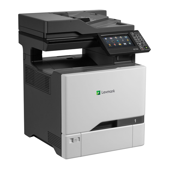
General information The Lexmark CX725 is a network‑capable, multi‑function, A4 laser printer that print both color and monochrome print jobs. All information in this service manual pertains to all models unless explicitly noted. The printers are available in the following models: Model Configurations... -
Page 26: Paper And Specialty Media Guide
7528 Paper and specialty media guide Paper guidelines Select the correct paper or specialty media to reduce printing problems. For the best print quality, try a sample of the paper or specialty media before buying large quantities. Paper characteristics The following paper characteristics affect print quality and reliability. Consider these factors before printing on them: Weight “Supported paper types and weights”... -
Page 27: Using Specialty Media
7528 Selecting paper Using the appropriate paper prevents jams and helps ensure trouble‑free printing. To help avoid paper jams and poor print quality: • Always use new, undamaged paper. • Before loading paper, know the recommended printable side of the paper. This information is usually indicated on the paper package. - Page 28 Print samples on labels being considered for use before buying large quantities. • For more information on label printing, characteristics, and design, see the Card Stock & Label Guide on the Lexmark Web site at http://support.lexmark.com. • Use labels designed specifically for laser printers.
-
Page 29: Supported Paper Sizes, Types, And Weights
7528 Supported paper sizes, types, and weights The following tables provide information on standard and optional paper sources and the sizes, types, and weights of paper they support. Note: For an unlisted paper size, select the closest larger listed size. Supported paper sizes Paper sizes supported by the trays and multipurpose feeder Paper size... - Page 30 7528 Paper size Dimensions 550‑sheet tray Multipurpose feeder Two‑sided printing 10 Envelope 105 x 241 mm (4.1 x 9.5 in.) Monarch Envelope 98.4 x 190.5 mm (3.9 x 7.5 in.) 98 x 162 mm (3.9 x 6.4 in.) to Other Envelope 176 x 250 mm (6.9 x 9.8 in.) Universal 104.8 x 148 mm (4.13 x 5.83 in.)
-
Page 31: Data Security Notice
7528 Paper size Dimensions Scanner glass Oficio 216 x 340 mm (8.5 x 13.4 in.) Universal 104.8 x 148 mm (4.13 x 5.83 in.) to 215.9 x 360 mm (8.5 x 14.17 in.) 76.2 x 123.8 mm (3 x 4.9 in.) to 215.9 x 1321 mm (8.5 x 52 in.) Custom scan size Supported only in long‑edge orientation. -
Page 32: Tools Required For Service
7528 • Hard disk memory—Some printers have a hard disk drive installed. The printer hard disk is designed for printer-specific functionality and cannot be used for the long‑term storage of data that is not print-related. The hard disk does not provide the capability for users to extract information, create folders, create disk or network file shares, or transfer FTP information directly from a client device. - Page 33 7528 • Diagonal side cutters • Spring hook • Feeler gauges • Analog or digital multimeter • Parallel wrap plug 1319128 • Twinax/serial debug cable 1381963 • Coax/serial debug cable 1381964 • Flash light (optional) • 3 mm hex wrench General information...
- Page 34 7528...
-
Page 35: Diagnostic Information
7528 Diagnostic information CAUTION—SHOCK HAZARD: To avoid the risk of electrical shock and to prevent damage to the printer, remove the power cord from the electrical outlet before you connect or disconnect any cable or electronic card or assembly for personal safety and to prevent damage to the printer. Disconnect any connections between the printer and computers or peripherals. -
Page 36: Fixing Print Quality Issues
7528 The progress bar appears on the splash screen. The printer begins to POST, and the motors and sensors are polled and tested. Scanner calibration starts. The home screen displays. Printer calibration may begin. Note: If any of the tests fail, the printer displays an error code. Fixing print quality issues Initial print quality check Before troubleshooting print problems, perform the following:... - Page 37 7528 Actions Step 1 Go to step 3. Go to step 2. From the home screen, touch Settings > Device > Preferences. Check if the paper type and size settings match the paper type and size set on the tray. Do the settings match? Step 2 Go to step 3.
-
Page 38: Background Or Gray Background Check
7528 Background or gray background check Leading edge ABCDE ABCDE ABCDE Trailing edge Action Step 1 Go to step 2. Go to step 3. From the home screen, touch Settings > Reports > Device > Device Statistics. Check the status of the imaging unit if it was recently replaced. Does the status show that the imaging unit was recently replaced? Step 2 Go to step 3. -
Page 39: Blank Or White Pages Check
7528 Action Step 8 Go to step 9. The problem is solved. Remove the printhead, and then clean the printhead lenses. See “Printhead removal” on page 413. Does the problem remain? Step 9 Contact the next The problem is level of support. solved. - Page 40 7528 Action Step 5 Go to step 6. The problem is solved. • If the affected color is cyan, magenta, or yellow, then replace the developer unit of the affected color. • If the affected color is black, then replace the imaging unit. Does the problem remain? Step 6 Go to step 8.
-
Page 41: Gapping Or Half Color Page Check
7528 Action Step 13 Go to step 14. The problem is solved. Replace the cable. Does the problem remain? Step 14 Go to step 15. The problem is solved. Replace the printhead. See “Printhead removal” on page 413. Does the problem remain? Step 15 Contact the next The problem is... -
Page 42: Blurred Print Or Color Misalignment Check
7528 Action Step 4 Go to step 5. The problem is solved. • If the affected color is cyan, magenta, or yellow, then replace the developer unit of the affected color. • If the affected color is black, then replace the imaging unit. Does the problem remain? Step 5 Contact the next... -
Page 43: Horizontal Colored Lines Or Banding Check
7528 Action Step 6 Go to step 7. The problem is solved. Perform the color alignment service check for all the colors. Does the problem remain? Step 7 Go to step 8. The problem is solved. Perform the auto alignment sensors service check. Does the problem remain? Step 8 Go to step 9. - Page 44 7528 Actions Step 1 Go to step 2. Go to step 3. Enter the Diagnostics menu, and then navigate to: Advanced Print Quality Samples > Advanced Print Quality Samples Check the test page for lines. Are the lines white? Step 2 Go to step 3.
-
Page 45: Text Or Images Cut Off Check
7528 Text or images cut off check Leading edge ABCDE ABCDE ABCDE Trailing edge Actions Step 1 Contact the next Go to step 2. level of support. From the home screen, touch Settings > Device > Preferences. Check if the paper type and size settings match the paper type and size set on the tray. -
Page 46: Vertical White Lines Check
7528 Action Step 5 Go to step 6. Go to step 7. Check the printer for toner leaks. Are there toner leaks? Step 6 Go to step 7. The problem is solved. Clean the printer thoroughly using a toner vacuum. Perform a print job to clear the remaining toner from the imaging components. - Page 47 7528 Action Step 1 Go to step 5. Go to step 2. Enter the Diagnostics menu, and then navigate to: Advanced Print Quality Samples > Advanced Print Quality Samples Check the test page. Did the print defect appear on all the pages? Step 2 Go to step 3.
-
Page 48: Ghost Images Check
7528 Ghost images check Leading edge A B C D A B C D A B C D A B C D Trailing edge Action Step 1 Go to step 2. Go to step 4. From the home screen, touch Status/supplies > Hardware. Check the status of the black and color imaging components. -
Page 49: Solid Color Or Black Image Check
7528 Action Step 7 Contact the next The problem is level of support. solved. Replace the fuser. See “Fuser removal” on page 387. Does the problem remain? Solid color or black image check Action Step 1 Go to step 2. Go to step 3. -
Page 50: Vertical Colored Lines Or Banding Check
7528 Action Step 5 Go to step 6. The problem is solved. Replace the printhead. See “Printhead removal” on page 413. Does the problem remain? Step 6 Go to step 7. The problem is solved. Check the toner cartridge contacts for damage, and replace if necessary. -
Page 51: Image Void Scan Direction Check
7528 Action Step 1 Go to step 2. Go to step 4. Enter the Diagnostics menu, and then navigate to: Advanced Print Quality Samples > Advanced Print Quality Samples Check the test page. Is only one color producing the defect? Step 2 Go to step 3. - Page 52 7528 Action Step 3 Go to step 4. Go to step 5. Check if the problem affects only one color. Does the problem affect only one color? Step 4 Go to step 6. The problem is solved. • If the affected color is cyan, magenta, or yellow, then reseat the developer unit of the affected color.
-
Page 53: Image Void Process Direction Check
7528 Image void process direction check Action Step 1 Go to step 2. The problem is solved. Load paper from a fresh package. Note: Paper may absorb moisture due to high humidity. Store paper in its original wrapper until it is ready to be used. Does the problem remain? Step 2 Go to step 3. -
Page 54: Dark Print Check
7528 Action Step 9 Go to step 10. The problem is solved. Replace the printhead. See “Printhead removal” on page 413. Does the problem remain? Step 10 Contact the next The problem is level of support. solved. Replace the controller board. See “Controller board removal”... -
Page 55: Missing Color Check
7528 Action Step 5 Go to step 6. The problem is solved. Remove the imaging kit, and then reseat the developer unit of the affected color. Does the problem remain? Step 6 Go to step 7. The problem is solved. Check the HVPS cable for proper connection and damage, and replace if necessary. -
Page 56: Uneven Print Density Check
7528 Action Step 2 Go to step 3. The problem is solved. Reseat all the developer units in the imaging kit. Enter the Diagnostics menu, and then navigate to: Advanced Print Quality Samples > Advanced Print Quality Samples Check the test page. Does the problem remain? Step 3 Go to step 4. -
Page 57: Repeating Defects Check
7528 Action Step 2 Go to step 3. The problem is solved. Change the paper size and type, or adjust the size settings in the tray. Does the problem remain? Step 3 Go to step 4. Go to step 5. Check the paper for texture or rough finish. - Page 58 7528 Action Step 4 Contact the next The problem is level of support. solved. • If the affected color is cyan, magenta, or yellow, then replace the developer unit of the affected color. • If the affected color is black, then replace the imaging unit. Does the problem remain? Step 5 Go to step 6.
-
Page 59: Random Marks Check
7528 Random marks check Action Step 1 Go to step 2. Go to step 3. Check the printer for toner leaks. Are there toner leaks? Step 2 Go to step 3. The problem is solved. Clean the printer thoroughly using a toner vacuum. Perform a print job to clear the remaining toner from the imaging components. - Page 60 7528 Action Step 3 Go to step 4. Go to step 12. Enter the Diagnostics menu, and then navigate to: Advanced Print Quality Samples > Advanced Print Quality Samples Check the test page. Is only one color affected? Step 4 Go to step 6.
- Page 61 7528 Action Step 11 Go to step 12. The problem is solved. Replace the motor. See “Motor (EP drive) removal” on page 350. Does the problem remain? Step 12 Go to step 14. Go to step 13. Remove the printhead, and then check the printhead lenses for dust or debris.
-
Page 62: Skewed Print Service Check
7528 Action Step 20 Go to step 21. The problem is solved. Reseat the HVPS and make sure that the contacts freely move. Does the problem remain? Step 21 Go to step 22. The problem is solved. Replace the transfer module. See “Transfer module removal”... - Page 63 7528 Action Step 6 Go to step 8. Go to step 7. Check the isolation unit for dust or debris. Is the isolation unit free of dust or debris? Step 7 Go to step 8. The problem is solved. Remove the dust or debris. Does the problem remain? Step 8 Go to step 11.
-
Page 64: Fixing Scan Quality Issues
7528 Fixing scan quality issues Dark image quality (using the ADF or scanner) check Actions Step 1 Go to step 2. Go to step 3. Isolate the scanner system by printing the advanced print quality samples directly from the printer. Enter the Diagnostics menu, and then navigate to: Advanced Print Quality Samples >... -
Page 65: Vertical Lines (Process Direction Using The Adf) Check
7528 Actions Step 8 Contact the next The problem is level of support. solved. Replace the printer controller board. See “Controller board removal” on page 409. Does the problem remain? Vertical lines (process direction using the ADF) check Actions Step 1 Go to step 2. -
Page 66: Spots (Using The Flatbed Scanner) Check
7528 Actions Step 7 Contact the next The problem is level of support. solved. Replace the flatbed. See “Flatbed removal” on page 435. Perform a scan-to-print test using both the ADF and scanner unit assemblies. Does the problem remain? Spots (using the flatbed scanner) check Actions Step 1 Go to step 2. -
Page 67: Adf Skew Check
7528 Actions Step 6 Contact the next The problem is level of support. solved. Replace the flatbed. See “Flatbed removal” on page 435. Perform a scan-to-print test using both the ADF and scanner unit assemblies. Does the problem remain? ADF skew check Actions Step 1 Go to step 2. - Page 68 7528 Actions Step 7 Go to step 8. The problem is solved. Open, and then properly close the following ADF top cover. Does the problem remain? Step 8 Go to step 9. The problem is solved. From the home screen, navigate to: Settings >...
-
Page 69: Media Damage (Using The Adf) Check
7528 Media damage (using the ADF) check Actions Step 1 Go to step 2. Go to step 3. Isolate the scanner system by printing the advanced print quality samples directly from the printer. Enter the Diagnostics menu, and then navigate to: Advanced Print Quality Samples >... -
Page 70: Paper Jams
7528 Paper jams Avoiding jams Load paper properly • Make sure that the paper lies flat in the tray. Correct loading of paper Incorrect loading of paper • Do not load or remove a tray while the printer is printing. •... -
Page 71: Identifying Jam Locations
7528 • Flex, fan, and align the paper edges before loading. • Do not use paper that has been cut or trimmed by hand. • Do not mix paper sizes, weights, or types in the same tray. • Make sure that the paper size and type are set correctly on the computer or printer control panel. •... -
Page 72: Paper Jam In Trays
7528 Paper jam in trays Pull out the tray. Warning—Potential Damage: A sensor inside the optional tray is easily damaged by static electricity. Touch a metal surface before removing the jammed paper in the tray. Remove the jammed paper. Note: Make sure that all paper fragments are removed. Insert the tray. -
Page 73: Paper Jam Behind Door E
7528 Paper jam behind door E Open door E. Remove the jammed paper. Note: Make sure that all paper fragments are removed. Close door E. Paper jam in the multipurpose feeder Remove paper from the multipurpose feeder. Pull out the tray. Remove the jammed paper. -
Page 74: Paper Jam In The Standard Bin
7528 Insert the tray. Paper jam in the standard bin Remove the jammed paper. Note: Make sure that all paper fragments are removed. Open doors A and D, and then remove any paper fragments. CAUTION—HOT SURFACE: The inside of the printer might be hot. To reduce the risk of injury from a hot component, allow the surface to cool before touching it. -
Page 75: Paper Jam In Door A
7528 Close doors D and A. Paper jam in door A Paper jam in the fuser Open door A. CAUTION—HOT SURFACE: The inside of the printer might be hot. To reduce the risk of injury from a hot component, allow the surface to cool before touching it. Remove the jammed paper. - Page 76 7528 Open the fuser access door. Remove the jammed paper. Note: Make sure that all paper fragments are removed. Close door A. Diagnostic information...
- Page 77 7528 Paper jam in the duplex unit Open door A. CAUTION—HOT SURFACE: The inside of the printer might be hot. To reduce the risk of injury from a hot component, allow the surface to cool before touching it. Open the duplex cover. Remove the jammed paper.
-
Page 78: Paper Jams
7528 200 paper jams 200 paper jam messages Error code Description Action 200.05 Paper fed from the MPF never cleared the sensor “Sensor (input): Paper failed to clear (input). service check” on page 200.12 Paper fed from tray 1 was detected earlier than “Sensor (input): Paper arrived too early expected at the sensor (input). - Page 79 7528 Sensor (input): Paper arrived too early service check Action Step 1 Go to step 3. Go to step 2. From the home screen, touch Settings > Device > Preferences. Check if the paper size matches the size set on the tray guides. Does the paper size match the size set on the tray? Step 2 Go to step 3.
- Page 80 7528 Action Step 2 Go to step 3. The problem is solved. Change the paper size or adjust the size setting in the tray. Does the problem remain? Step 3 Go to step 5. Go to step 4. Check the paper path for paper jams and fragments. Is the paper path free of jams and fragments? Step 4 Go to step 5.
- Page 81 7528 Sensor (input): Paper failed to clear service check Action Step 1 Go to step 3. Go to step 2. From the home screen, touch Settings > Device > Preferences. Check if the paper size matches the size set on the tray guides. Does the paper size match the size set on the tray? Step 2 Go to step 3.
- Page 82 7528 Action Step 9 Go to step 10. The problem is solved. Check the motor cable for proper connection and damage, and replace if necessary. Does the problem remain? Step 10 Contact the next The problem is level of support. solved.
- Page 83 7528 Action Step 7 Go to step 9. The problem is solved. Enter the Diagnostics menu, and then navigate to: Printer diagnostics & adjustments > Sensor tests Find the sensor (Input). Does the sensor status change while toggling the sensor? Step 8 Go to step 9.
-
Page 84: Paper Jams
7528 Action Step 5 Go to step 8. Go to step 6. Enter the Diagnostics menu, and then navigate to: Printer diagnostics & adjustments > Sensor tests Find the sensor (Input). Does the sensor status change while toggling the sensor? Step 6 Go to step 7. -
Page 85: Paper Jams
7528 Action Step 3 Go to step 5. Go to step 4. Check the paper path for partially fed or jammed paper. Is the paper path free of partially fed or jammed paper? Step 4 Go to step 5. The problem is solved. - Page 86 7528 Error code Description Action 202.24 Paper fed from tray 2 cleared the sensor (fuser “Sensor (fuser exit): Paper cleared too exit) earlier than expected. early service check” on page 202.25 Paper fed from tray 2 never cleared the sensor “Sensor (fuser exit): Paper failed to clear (fuser exit).
- Page 87 7528 Action Step 4 Go to step 5. The problem is solved. Remove the paper jams and fragments. Does the problem remain? Step 5 Go to step 7. Go to step 6. Check the fuser rollers for damage. Are the rollers free of damage? Step 6 Go to step 7.
- Page 88 7528 Action Step 6 Go to step 7. The problem is solved. Remove the obstructions in the fuser area. Does the problem remain? Step 7 Go to step 8. The problem is solved. Check the fuser for damage or life expiration, and replace if necessary.
- Page 89 7528 Action Step 14 Go to step 15. The problem is solved. Replace the motor. See “Motor (fuser) removal” on page 372. Perform a print job. Does the problem remain? Step 15 Contact the next Go to step 16. level of support. Enter the Diagnostics menu, and then navigate to: Printer diagnostics &...
- Page 90 7528 Action Step 4 Go to step 5. The problem is solved. Remove the jams and fragments. Does the problem remain? Step 5 Go to step 7. Go to step 6. Check the fuser for obstructions. Is the fuser free from obstructions? Step 6 Go to step 7.
- Page 91 7528 Action Step 12 Go to step 13. The problem is solved. Check the motor cable for proper connection and damage, and replace if necessary. Does the problem remain? Step 13 Contact the next The problem is level of support. solved.
- Page 92 7528 Action Step 7 Go to step 8. The problem is solved. Replace the fuser. See “Fuser removal” on page 387. Does the problem remain? Step 8 Contact the next The problem is level of support. solved. Perform a print job. Does the problem remain? Sensor (fuser exit) static jam service check Action...
-
Page 93: Paper Jams
7528 Action Step 7 Contact the next The problem is level of support. solved. Check the sensor for damage, and replace if necessary. Perform a print job. Does the problem remain? 203 paper jams 203 paper jam messages Error code Description Action 203.91... -
Page 94: Paper Jams
7528 Action Step 6 Go to step 7. The problem is solved. Check the cable on the JDSNS connector on the controller board for proper connection and damage, and replace if necessary. Does the problem remain? Step 7 Contact the next The problem is level of support. -
Page 95: Paper Jams
7528 Action Step 5 Contact the next Go to step 6. level of support. Enter the Diagnostics menu, and then navigate to: Printer diagnostics & adjustments > Sensor tests Find the sensor (Narrow media). Does the sensor status change while toggling the sensor? Step 6 Go to step 7. -
Page 96: Paper Jams
7528 Action Step 4 Go to step 5. The problem is solved. Remove the partially fed or jammed paper. Does the problem remain? Step 5 Contact the next Go to step 6. level of support. Enter the Diagnostics menu, and then navigate to: Printer diagnostics &... - Page 97 7528 Error code Description Action 230.25 Paper fed from tray 2 never cleared the sensor “Sensor (duplex path 1): Paper failed to (duplex path 1). clear service check” on page 230.32 Paper fed from tray 3 was detected earlier than “Sensor (duplex path 1): Paper arrived expected at the sensor (duplex path 1).
- Page 98 7528 Action Step 5 Contact the next The problem is level of support. solved. Perform a print job. Does the problem remain? Sensor (duplex path 1): Paper failed to arrive service check Action Step 1 Go to step 3. Go to step 2. From the home screen, touch Settings >...
- Page 99 7528 Action Step 9 Go to step 11. Go to step 10. Enter the Diagnostics menu, and then navigate to: Printer diagnostics & adjustments > Sensor tests Find the sensor (Duplex path 1). Does the sensor status change while toggling the sensor? Step 10 Go to step 11.
- Page 100 7528 Action Step 4 Go to step 5. The problem is solved. Change the paper size or adjust the size setting in the tray. Does the problem remain? Step 5 Go to step 7. Go to step 6. Check the paper path for paper jams and obstructions. Is the paper path free of jams and obstructions? Step 6 Go to step 7.
- Page 101 7528 Action Step 12 Contact the next The problem is level of support. solved. Replace the motor. See “Motor (duplex/MPF) removal” on page 369. Perform a print job. Does the problem remain? Sensor (duplex path 1): Paper cleared too early service check Action Step 1 Go to step 3.
-
Page 102: Paper Jams
7528 Action Step 8 Contact the next The problem is level of support. solved. Perform a print job. Does the problem remain? 231 paper jams 231 paper jam messages Error code Description Action 231.12 Paper fed from tray 1 was detected earlier than “Sensor (duplex path 2): Paper arrived expected at the sensor (duplex path 2). - Page 103 7528 Sensor (duplex path 2): Paper arrived too early service check Action Step 1 Go to step 3. Go to step 2. From the home screen, touch Settings > Device > Preferences. Check if the paper size matches the size set on the tray guides. Does the paper size match the size set on the tray? Step 2 Go to step 3.
- Page 104 7528 Action Step 3 Go to step 5. Go to step 4. Check the duplex paper path for paper jams and obstructions. Is the paper path free of jams and obstructions? Step 4 Go to step 5. The problem is solved.
- Page 105 7528 Action Step 11 Go to step 12. The problem is solved. Check the duplex drive gears in the printer for damage, and replace if necessary. Does the problem remain? Step 12 Contact the next The problem is level of support. solved.
- Page 106 7528 Action Step 7 Go to step 10. Go to step 8. Enter the Diagnostics menu, and then navigate to: Printer diagnostics & adjustments > Sensor tests Find the sensor (Duplex path 2). Does the sensor status change while toggling the sensor? Step 8 Go to step 9.
- Page 107 7528 Action Step 2 Go to step 3. The problem is solved. Change the paper size or adjust the size setting in the tray. Does the problem remain? Step 3 Go to step 5. Go to step 4. Check the duplex rollers for damage. Are the rollers free of damage? Step 4 Go to step 5.
-
Page 108: Paper Jams
7528 Action Step 2 Go to step 3. The problem is solved. Change the paper size or adjust the size setting in the tray. Does the problem remain? Step 3 Go to step 5. Go to step 4. Check the paper path for partially fed or jammed paper. Is the paper path free of partially fed or jammed paper? Step 4 Go to step 5. - Page 109 7528 Error code Description Action 232.91 Paper remains detected at the sensor (duplex “Sensor (duplex path 2) static jam path 2) after the printer is turned on. service check” on page 107. Sensor (MPF/pass‑through): Paper (duplex job) failed to arrive service check Action Step 1 Go to step 3.
- Page 110 7528 Action Step 9 Go to step 10. The problem is solved. Check the sensor cable for proper connection and damage, and replace if necessary. Does the problem remain? Step 10 Go to step 11. The problem is solved. Replace the isolation unit. See “Isolation unit removal”...
- Page 111 7528 Sensor (MPF/pass‑through): Paper (duplex job) failed to clear service check Action Step 1 Go to step 3. Go to step 2. From the home screen, touch Settings > Device > Preferences. Check if the paper size matches the size set on the tray guides. Does the paper size match the size set on the tray? Step 2 Go to step 3.
- Page 112 7528 Action Step 10 Contact the next Go to step 11. level of support. Enter the Diagnostics menu, and then navigate to: Printer diagnostics & adjustments > Motor tests > Deskew Touch Start. Does the motor run? Step 11 Go to step 12. The problem is solved.
-
Page 113: Paper Jams
7528 Action Step 5 Go to step 8. Go to step 6. Enter the Diagnostics menu, and then navigate to: Printer diagnostics & adjustments > Sensor tests Find the sensor (Input). Does the sensor status change while toggling the sensor? Step 6 Go to step 7. - Page 114 7528 Error code Description Action 240.82 The motor (duplex/MPF) has stalled. “Motor (duplex/MPF) jam service check” on page 124. 240.84 The motor (duplex/MPF) failed to achieve expected speed or has stalled. 240.91 Paper remains detected at the sensor (MPF/pass- “Sensor (MPF/pass-through) static jam through) after the printer is turned on.
- Page 115 7528 Action Step 8 Go to step 9. Contact the next level of support. Check the sensor and sensor flag for damage. Is the sensor or sensor flag damaged? Step 9 Contact the next The problem is level of support. solved.
- Page 116 7528 Action Step 8 Go to step 9. The problem is solved. Replace the pick rollers. Does the problem remain? Step 9 Go to step 11. Go to step 10. Check the pick rollers for proper installation. Firmly press the pick roller assembly upward to make sure that it is properly engaged to the shaft.
- Page 117 7528 Action Step 17 Contact the next Go to step 18. level of support. Enter the Diagnostics menu, and then navigate to: Printer diagnostics & adjustments > Motor tests > Duplex/MPF Select a setting, and then touch Start. Does the motor run? Step 18 Go to step 19.
- Page 118 7528 Action Step 6 Go to step 7. The problem is solved. Replace the crumpled or damaged paper. Does the problem remain? Step 7 Go to step 9. Go to step 8. Check the condition of the tray 2 pick rollers. Are the pick rollers free from excess wear, contamination, and damage? Step 8...
- Page 119 7528 Action Step 15 Go to step 16. The problem is solved. Check the sensor for damage, and replace if necessary. Does the problem remain? Step 16 Go to step 19. Go to step 17. Enter the Diagnostics menu, and then navigate to: Printer diagnostics &...
- Page 120 7528 Action Step 3 Go to step 6. Go to step 4. Enter the Diagnostics menu, and then navigate to: Printer diagnostics & adjustments > Sensor tests Find the sensor (MPF/pass‑through). Does the sensor status change while toggling the sensor? Step 4 Go to step 5.
- Page 121 7528 Action Step 11 Contact the next The problem is level of support. solved. Replace the motor (550-sheet tray pass‑through). See “Motor (550-sheet tray pass‑through) removal” on page 445. Perform a print job. Does the problem remain? Sensor (MPF/pass-through): Paper (tray 4) failed to arrive service check Action Step 1 Go to step 3.
- Page 122 7528 Action Step 8 Go to step 11. Go to step 9. Enter the Diagnostics menu, and then navigate to: Printer diagnostics & adjustments > Sensor tests Find the sensor (Pass‑through (tray 2)). Does the sensor status change while toggling the sensor? Step 9 Go to step 10.
- Page 123 7528 Action Step 15 Go to step 16. The problem is solved. Check the motor cable for proper connection and damage, and replace if necessary. Does the problem remain? Step 16 Go to step 17. The problem is solved. Replace the motor (550-sheet tray pass‑through). See “Motor (550-sheet tray pass‑through) removal”...
- Page 124 7528 Action Step 3 Contact the next Go to step 4. level of support. Enter the Diagnostics menu, and then navigate to: Printer diagnostics & adjustments > Sensor tests Find the sensor (MPF/pass‑through). Does the sensor status change while toggling the sensor? Step 4 Go to step 5.
-
Page 125: Paper Jams
7528 Action Step 6 Go to step 7. Go to step 8. Check the duplex and MPF paper path exiting tray 1. Is the paper path free of fragments and contamination? Step 7 Go to step 8. The problem is solved. - Page 126 7528 Error code Description Action 241.82 The motor (tray 1 pick) failed to achieve expected “Motor (tray 1 pick) jam service check” speed or has stalled. on page 132. 241.83 241.84 241.91 Paper remains detected at the sensor (tray 1 pick) “Sensor (tray 1 pick) static jam service after the printer is turned on.
- Page 127 7528 Action Step 8 Go to step 9. The problem is solved. Check the sensor for damage and replace if necessary. See “Sensor (input) removal” on page 395. Does the problem remain? Step 9 Contact the next Go to step 10. level of support.
- Page 128 7528 Action Step 5 Go to step 6. Go to step 7. Check the paper condition in tray 1. Is the paper crumpled or damaged? Step 6 Go to step 7. The problem is solved. Replace the crumpled or damaged paper. Does the problem remain? Step 7 Go to step 9.
- Page 129 7528 Action Step 14 Go to step 15. The problem is solved. Check the sensor cable for proper connection and damage, and replace if necessary. Does the problem remain? Step 15 Go to step 16. The problem is solved. Check the sensor for damage, and replace if necessary. See “Sensor (input) removal”...
- Page 130 7528 Action Step 2 Go to step 3. The problem is solved. Change the paper size or adjust the size setting in the tray. Does the problem remain? Step 3 Go to step 4. Go to step 5. Check the tray for overfilling. Is the tray overfilled? Step 4 Go to step 5.
- Page 131 7528 Action Step 4 Go to step 5. The problem is solved. Remove the excess paper from the tray. Does the problem remain? Step 5 Go to step 6. Go to step 7. Check the paper condition in the tray. Is the paper crumpled or damaged? Step 6 Go to step 7.
- Page 132 7528 Action Step 2 Go to step 3. The problem is solved. Change the paper size or adjust the size setting in the tray. Does the problem remain? Step 3 Contact the next Go to step 4. level of support. Enter the Diagnostics menu, and then navigate to: Printer diagnostics &...
-
Page 133: Paper Jams
7528 Action Step 5 Go to step 7. Go to step 6. Check the paper path exiting the tray. Is the paper path free of fragments and contamination? Step 6 Go to step 7. The problem is solved. Clean the paper path. Does the problem remain? Step 7 Contact the next... - Page 134 7528 Error code Description Action 242.26 Paper fed from tray 2 was picked but it never “Sensor (tray [x] pass-through): Tray [x] arrived at the sensor (tray 2 trailing edge). failed to pick service check” on page 150. 242.27 Paper fed from tray 2 never cleared the sensor “Sensors (tray [x] trailing edge and (tray 2 trailing edge).
- Page 135 7528 Error code Description Action 242.47 Paper fed from tray 4 never cleared the sensor “Sensors (tray [x] trailing edge and (tray 2 trailing edge). pass‑through): Paper failed to clear service check” on page 152. 242.48 Paper fed from tray 4 was detected later than “Sensors (tray [x] trailing edge and expected at the sensor (tray 2 pass-through) or at pass-through): Paper arrived too late...
- Page 136 7528 Error code Description Action 243.35 Paper fed from tray 3 cleared the sensor (tray 3 “Sensors (tray [x] trailing edge and pass-through) or the sensor (tray 3 trailing edge) pass-through): Paper cleared too late later than expected. service check” on page 147.
- Page 137 7528 Error code Description Action 243.95 Paper cleared the sensor (tray 3 pass-through) or “Sensors (tray [x] trailing edge and the sensor (tray 3 trailing edge) later than pass-through): Paper cleared too late expected. Paper source is undetermined. service check” on page 147.
- Page 138 7528 Error code Description Action 244.94 Paper cleared the sensor (tray 4 pass-through) or “Sensors (tray [x] trailing edge and pass- the sensor (tray 4 trailing edge) earlier than through): Paper cleared too early service expected. Paper source is undetermined. check”...
- Page 139 7528 Action Step 6 Go to step 8. Go to step 7. Reseat the sensor cable, and then check the sensor for misalignment and damage. Is the sensor properly installed and free of damage? Step 7 Go to step 8. The problem is solved.
- Page 140 7528 Action Step 3 Go to step 5. Go to step 4. Check the paper path for partially fed or jammed paper. Is the paper path free of partially fed or jammed paper? Step 4 Go to step 5. The problem is solved.
- Page 141 7528 Action Step 11 Contact the next The problem is level of support. solved. Perform a print test. Does the problem remain? Sensor (tray 2 pass-through): Paper failed to arrive service check Action Step 1 Go to step 3. Go to step 2. From the home screen, touch Settings >...
- Page 142 7528 Action Step 9 Go to step 11. Go to step 10. Check the paper path for partially fed or jammed paper. Is the paper path free of partially fed or jammed paper? Step 10 Go to step 11. The problem is solved.
- Page 143 7528 Action Step 17 Go to step 20. Go to step 18. Enter the Diagnostics menu, and then navigate to: Additional input tray diagnostics > Motor tests Find the motor (Pass-through (tray 3)), and then touch Start. Does the motor run? Step 18 Go to step 20.
- Page 144 7528 Action Step 5 Go to step 6. Go to step 7. Check the paper tray for overfilling. Is the paper tray overfilled? Step 6 Go to step 7. The problem is solved. Remove the excess paper from the tray. Does the problem remain? Step 7 Go to step 8.
- Page 145 7528 Action Step 14 Go to step 17. Go to step 15. Enter the Diagnostics menu, and then navigate to: Additional input tray diagnostics > Motor tests Find the motor (Pass-through (tray 3)), and then touch Start. Does the motor run? Step 15 Go to step 17.
- Page 146 7528 Sensors (tray [x] trailing edge and pass-through): Paper cleared too early service check Action Step 1 Go to step 3. Go to step 2. From the home screen, touch Settings > Device > Preferences. Check if the paper size matches the size set on the tray guides. Does the paper size match the size set on the tray? Step 2 Go to step 3.
- Page 147 7528 Action Step 10 Go to step 12. Go to step 11. Reseat the sensor cable, and then check the sensor for misalignment and damage. Is the sensor properly installed and free of damage? Step 11 Go to step 12. The problem is solved.
- Page 148 7528 Action Step 3 Go to step 5. Go to step 4. Check if the paper size matches the size set on the tray guides. Does the paper size match the size set on the tray? Step 4 Go to step 5. The problem is solved.
- Page 149 7528 Action Step 12 Go to step 13. The problem is solved. Reinstall or replace the motor. See “Motor (duplex/MPF) removal” on page 369. Does the problem remain? Step 13 Go to step 16. Go to step 14. Enter the Diagnostics menu, and then navigate to: Additional input tray diagnostics >...
- Page 150 7528 Sensor (tray [x] pass-through): Tray [x] failed to pick service check Action Step 1 Go to step 3. Go to step 2. From the home screen, touch Settings > Device > Preferences. Check if the paper size matches the size set on the tray guides. Does the paper size match the size set on the tray? Step 2 Go to step 3.
- Page 151 7528 Action Step 10 Go to step 11. The problem is solved. Reinstall the pick roller assembly. Does the problem remain? Step 11 Go to step 13. Go to step 12. Check the condition of the pick rollers. Are the pick rollers free from excess wear, contamination, and damage? Step 12 Go to step 13.
- Page 152 7528 Action Step 18 Go to step 21. Go to step 19. Enter the Diagnostics menu, and then navigate to: Additional input tray diagnostics > Motor tests > Motor tests > Pick (tray [x]) Select a setting, and then touch Start. Does the motor run? Step 19 Go to step 21.
- Page 153 7528 Action Step 4 Go to step 5. The problem is solved. Remove the partially fed or jammed paper. Does the problem remain? Step 5 Go to step 8. Go to step 6. Enter the Diagnostics menu, and then navigate to: Additional input tray diagnostics >...
- Page 154 7528 Action Step 12 Go to step 14. Go to step 13. Reseat the sensor cable, and then check the sensor for misalignment and damage. Is the sensor properly installed and free of damage? Step 13 Go to step 14. The problem is solved.
- Page 155 7528 Action Step 3 Go to step 5. Go to step 4. Check if the paper size matches the size set on the tray guides. Does the paper size match the size set on the tray? Step 4 Go to step 5. The problem is solved.
- Page 156 7528 Action Step 13 Go to step 15. Go to step 14. Check the paper path exiting the paper tray. Is the paper path free of fragments and contamination? Step 14 Go to step 15. The problem is solved. Clean the paper path. Does the problem remain? Step 15 Go to step 18.
- Page 157 7528 Action Step 21 Go to step 22. The problem is solved. Replace the media feeder. See “Media feeder removal” on page 422. Does the problem remain? Step 22 Go to step 25. Go to step 23. Enter the Diagnostics menu, and then navigate to: Additional input tray diagnostics >...
-
Page 158: 28Y And 680 Paper Jams
7528 28y and 680 paper jams 28y and 680 paper jam messages Error Description Action code 280.11 The paper remains detected at the sensor “ADF paper jam service check” on page 158. (media present) after the printer is turned 280.13 The sensor (media present) did not detect the paper. - Page 159 7528 Actions Step 1 Go to step 2. The problem is solved. Resend the scan job. Does the problem remain? Step 2 Go to step 4. Go to step 3. Check the paper path for paper jams and fragments. Is the paper path free of fragments and debris? Step 3 Go to step 4.
- Page 160 7528 Actions Step 10 Go to step 12. Go to step 11. Enter the Diagnostics menu, and then navigate to: Scanner diagnostics > Motor tests > ADF pick Touch Start. Enter the Diagnostics menu, and then navigate to: Scanner diagnostics > Motor tests > ADF transport Touch Start.
- Page 161 7528 Actions Step 17 Contact the next Go to step 18. level of support. Check the following pins of the JADF1 connector on the controller board if the values are as shown: Pins 14 and 16 are +25V. Pins 15 and 22 are +3V. Pins 17, 18, and 23 are GND.
- Page 162 7528 Actions Step 7 Contact the next The problem is level of support. solved. Perform an ADF scan job. Does the problem remain? ADF top cover open service check Actions Step 1 Go to step 3. Go to step 2. Check if the ADF top cover is completely closed.
-
Page 163: User Attendance Messages
7528 ADF tray empty service check Actions Step 1 Go to step 2. The problem is solved. Load the scan documents properly in the ADF tray. Reset the printer, and then perform an ADF scan job. Does the problem remain? Step 2 The problem is Go to step 3. -
Page 164: User Attendance Error Messages
7528 Z code: • 31.xxN— Non-genuine Lexmark supply 32 user attendance error messages Error code Description Action 32.40z Cartridge compatibility problem. Replace the “Missing toner, developer, or unsupported black cartridge. photoconductor service check” on page 171. 32.41z Cartridge compatibility problem. Replace the unsupported cyan cartridge. -
Page 165: User Attendance Error Messages
33.50z Non-Lexmark black developer. The smart chip contents have been manipulated by a third party manufacturer. 33.64z Non-Lexmark color imaging unit. The smart chip contents have been manipulated by a third party manufacturer. Z codes: • 33.xxA— Non-genuine Lexmark supply •... -
Page 166: User Attendance Error Messages
7528 • 2— Europe Economic Area + extras (EEA+) • 5— Rest of Europe, Middle East, Africa (RoEMEA) • 7— Latin America, Asia Pacific (LAD / AP) (+Aus/ NZ) 43 user attendance error messages Error code Description Action 43.41z Cyan bottle TMC error. “Toner meter cycle (TMC) card service check”... -
Page 167: User Attendance Error Messages
7528 82 user attendance error messages Error code Description Action 82.11 The waste toner bottle is nearly full. The sensor “Waste toner bottle service check” on threshold has been reached. page 173. 82.19 The waste toner bottle is nearly full. The user- selected EWS set point has been reached. -
Page 168: User Attendance Error Messages
7528 84 user attendance error messages Error code Description Action 84.01 The imaging kit is nearly low. The “Cartridge or photoconductor error service photoconductor threshold has been reached. check” on page 174. 84.09 The imaging kit is nearly low. The user-selected EWS set point has been reached. -
Page 169: User Attendance Error Messages
7528 85 user attendance error messages Error code Description Action 85.01 The black imaging unit is nearly low. The “Cartridge or photoconductor error service photoconductor threshold has been reached. check” on page 174. 85.09 The black imaging unit is nearly low. The user‑selected EWS set point has been reached. -
Page 170: User Attendance Error Messages
7528 88 user attendance error messages Error code Description Action 88.01z The cartridge is nearly low. The TMC threshold “Cartridge or photoconductor error service has been reached. check” on page 174. 88.09z The cartridge is nearly low. The user‑selected EWS set point has been reached. 88.11z The cartridge is low, and [x] estimated pages remain. -
Page 171: Missing Toner, Developer, Or Photoconductor Service Check
7528 Error code Description Action Defective flash memory. “Flash memory failure service check” on page 177. Flash memory is full. “Insufficient flash memory service check” on page 177. Unformatted flash memory. “Flash memory failure service check” on page 177. Serial port or network error. “Flash memory failure service check”... - Page 172 7528 Action Step 3 Go to step 4. The problem is solved. Check the pogo pin contacts for damage, and replace if necessary. Does the problem remain? Step 4 Go to step 6. Go to step 5. Check the pogo pin contacts for dust or debris. Are the contacts free of dust or debris? Step 5 Go to step 6.
-
Page 173: Waste Toner Bottle Service Check
7528 Waste toner bottle service check Action Step 1 Go to step 2. The problem is solved. Reseat the waste toner bottle. Does the problem remain? Step 2 Go to step 4. Go to step 3. Check if the printer is placed on a flat surface. Is the printer placed on a flat surface? Step 3 Go to step 4. -
Page 174: Maintenance Kit Service Check
7528 Maintenance kit service check Action Warning—Potential Damage: Do not perform this step if the Contact the next The problem is printer is on. level of support. solved. Replace the required maintenance kit. Reset the maintenance counter. See “Maintenance kits” on page 480. -
Page 175: Mismatched Paper Size Service Check
7528 Mismatched paper size service check Action Step 1 Go to step 3. Go to step 2. From the home screen, touch Settings > Device > Preferences. Check if the paper size matches the size set on the tray guides. Does the paper size match the size set on the tray? Step 2 Go to step 3. -
Page 176: Insufficient Memory Service Check
7528 Insufficient memory service check Action Step 1 Go to step 2. The problem is solved. Reset the printer, and then navigate to: Settings > Print > Setup > Download Target > Disk Does the problem remain? Step 2 Go to step 3. The problem is solved. -
Page 177: Flash Memory Failure Service Check
7528 Flash memory failure service check Action Step 1 Go to step 2. The problem is solved. Navigate to Settings > Print > Job Accounting > Log Near Full Level. Make sure that the value is set to maximum. Does the problem remain? Step 2 Go to step 3. -
Page 178: Unsupported Internal Option Service Check
7528 Action Step 4 Go to step 5. The problem is solved. Check the controller board pins for damage, and replace if necessary. See “Controller board removal” on page 409. Does the problem remain? Step 5 Contact the next The problem is level of support. -
Page 179: Excess Options Service Check
7528 Action Step 3 Go to step 4. The problem is solved. If applicable, make sure that the option card is supported. Does the problem remain? Step 4 Go to step 5. The problem is solved. Check the controller board pins for damage, and replace if necessary. -
Page 180: Incompatible Hardware Option Service Check
7528 Action Step 6 Contact the next The problem is level of support. solved. Check the controller board pins for damage, and replace if necessary. See “Controller board removal” on page 409. Does the problem remain? Incompatible hardware option service check Action Step 1 Go to step 2. -
Page 181: Printer Hardware Errors
The problem is solved. Make sure that the firmware version is the latest. Note: The latest firmware versions are available on the Technical service bulletins at support.lexmark.com. Does the problem remain? Step 3 Go to step 4. The problem is solved. - Page 182 7528 Error code Description Action 100.35 The following sensors appear to be disconnected: “Sensor (duplex/MPF input) service check” on page 195. Sensor (MPF paper present) Sensor (duplex path 2) Sensor (fuser buckle) Sensor (narrow media) 100.36 The MPF paper present sensor is unplugged. 100.37 The duplex path 2 sensor is unplugged.
- Page 183 7528 110 error messages Error code Description Action 110.20 Printhead error was detected before the motor “Printhead service check” on page 197. was turned on. 110.21 No printhead power when the laser servo started. 110.31 Printhead error (no first Hysnc) was detected. 110.32 Printhead error (lost first Hysnc) was detected.
- Page 184 7528 121 error messages Error code Description Action 121.02 Fuser went over the required temperature during “Fuser service check” on page 199. EWC/line voltage detection. 121.03 Fuser hardware and driver mismatch. 121.06 Fuser power is at 100% but did not reach the required temperature.
- Page 185 7528 Error code Description Action 121.33 Fuser did not reach the required temperature while “Fuser service check” on page 199. the page is in the fuser. 121.34 Fuser did not reach the required temperature during steady state control. 121.35 Fuser too warm to power up and execute EWC/line voltage detection after a wrong fuser was installed.
-
Page 186: Error Message
7528 126 and 127 error messages Error code Description Action 126.01 LVPS line voltage error was detected. “LVPS service check” on page 200. 126.02 LVPS line voltage error was detected. 126.06 LVPS 25V line error was detected. 126.07 LVPS 5V rail was down during POR. 126.10 No line frequency was detected. - Page 187 7528 144 error messages Error code Description Action 144.80 The motor (Y developer) did not turn on. “Motor (Y developer) service check” on page 203. 144.81 The motor (Y developer) did not turn off. 144.82 The motor (Y developer) speed did not ramp up to the required level.
- Page 188 7528 149 error messages Error code Description Action 149.80 The motor (output) did not turn on. “Motor (output) service check” on page 206. 149.81 The motor (output) did not turn off. 149.82 The motor (output) speed did not ramp up to the required level.
- Page 189 7528 161 and 162 error messages Error code Description Action 161.80 The motor (tray 1 pick) did not turn on. “Tray pick roller assembly and lift motor service check” on page 211. 161.81 The motor (tray 1 pick) did not turn off. 161.82 The motor (tray 1 pick) speed did not ramp up to the required level.
- Page 190 7528 153 error messages Error code Description Action 153.80 The isolation unit did not turn on. “Isolation unit service check” on page 209. 153.81 The isolation unit did not turn off. 153.82 The isolation unit speed did not ramp up to the required level.
- Page 191 7528 166–168 error messages 166.80 The motor (tray 2 pass-through) did not turn on. “Motor (tray [x] transport) failure service check” on page 213. 166.81 The motor (tray 2 pass-through) did not turn off. 166.82 The motor (tray 2 pass-through) speed did not ramp up to the required level.
- Page 192 7528 Error code Description Action 172.82 The LVPS fuser fan peed did not ramp up to the “LVPS fuser fan service check” on required level. page 214. 172.83 The LVPS fuser fan stalled. 172.84 The LVPS fuser fan ran too slow. 172.85 The LVPS fuser fan ran too fast.
- Page 193 7528 Action Step 8 Go to step 9. The problem is solved. Check the green, yellow, and blue cables connecting the JPKSNS1 connector to the blue and green cables on the isolation unit for proper connection and damage. Replace the cables if necessary. Does the problem remain? Step 9 Contact the next...
- Page 194 7528 Action Step 4 Contact the next The problem is level of support. solved. Check the sensors for damage, and replace if necessary. Does the problem remain? Fuser sensors service check Action Step 1 Go to step 2. Go to step 3. Check the error that appeared.
- Page 195 7528 Sensor (duplex/MPF input) service check Action Step 1 Go to step 2. Go to step 5. Check the error that appeared. Is the error 100.35? Step 2 Go to step 4. Go to step 3. Remove the cable cover from the front door. Check if the cable is properly connected to the door and to the JMSNS1 connector on the controller board.
- Page 196 7528 Sensor (weather station) service check Action Step 1 Go to step 2. The problem is solved. Check the sensor cable for proper connection and damage, and replace if necessary. Does the problem remain? Step 2 Contact the next The problem is level of support.
-
Page 197: Printhead Service Check
7528 Action Step 6 Go to step 7. The problem is solved. Replace the input option controller board. See “550-sheet tray controller board assembly removal” on page 451. Does the problem remain? Step 7 Contact the next The problem is level of support. - Page 198 7528 Motor (fuser) service check Action Step 1 Go to step 2. The problem is solved. Reset the printer. Does the problem remain? Step 2 Go to step 3. Go to step 4. Check the fuser for damage or life expiration, and replace if necessary.
-
Page 199: Fuser Service Check
7528 Fuser service check Action Step 1 Go to step 3. Go to step 2. Check the fuser for proper installation. Is the fuser properly installed? Step 2 Go to step 3. The problem is solved. Reinstall the fuser. Does the problem remain? Step 3 Go to step 5. -
Page 200: Lvps Service Check
7528 LVPS service check Action Step 1 Go to step 2. The problem is solved. Reset the printer. Does the problem remain? Step 2 Go to step 4. Go to step 3. Check the LVPS cable on the JLVPS connector on the controller board for proper connection. - Page 201 7528 Action Step 3 Go to step 4. The problem is solved. Reconnect the cable. Does the problem remain? Step 4 Go to step 5. The problem is solved. Check the cable for damage, and replace if necessary. Does the problem remain? Step 5 Go to step 6.
- Page 202 7528 Action Step 4 Go to step 5. The problem is solved. Replace the motor (EP drive). See “Motor (EP drive) removal” on page 350. Does the problem remain? Step 5 Contact the next The problem is level of support. solved.
- Page 203 7528 Motor (Y developer) service check Action Step 1 Go to step 2. The problem is solved. Reset the printer. Does the problem remain? Step 2 Go to step 3. Go to step 6. Remove the imaging kit, and then remove the transfer module. “Transfer module removal”...
- Page 204 7528 Action Step 9 Go to step 10. The problem is solved. Replace the motor (Y developer). See “Motor (EP drive) removal” on page 350. Does the problem remain? Step 10 Contact the next The problem is level of support. solved.
- Page 205 7528 Action Step 6 Go to step 7. The problem is solved. Reconnect the cable. Does the problem remain? Step 7 Go to step 8. The problem is solved. Check the cable for damage, and replace if necessary. Does the problem remain? Step 8 Go to step 9.
- Page 206 7528 Action Step 5 Go to step 7. Go to step 6. Check the cable on the motor and on the JMTR1 connector on the controller board for proper connection. Is the cable properly connected at both ends? Step 6 Go to step 7.
- Page 207 7528 Action Step 4 Go to step 5. The problem is solved. Replace the motor. See “Motor (output) removal” on page 351. Does the problem remain? Step 5 Go to step 6. The problem is solved. Reset the printer. Does the problem remain? Step 6 Contact the next The problem is...
- Page 208 7528 Action Step 6 Contact the next The problem is level of support. solved. Replace the controller board. See “Controller board removal” on page 409. Does the problem remain? Motor (K developer) service check Action Step 1 Go to step 2. The problem is solved.
- Page 209 7528 Action Step 7 Go to step 8. The problem is solved. Reconnect the cable. Does the problem remain? Step 8 Go to step 9. The problem is solved. Check the cable for damage, and replace if necessary. Does the problem remain? Step 9 Go to step 10.
- Page 210 7528 Action Step 5 Go to step 7. Go to step 6. Check the cable on the motor and on the JMTR1 connector on the controller board for proper connection. Is the cable properly connected at both ends? Step 6 Go to step 7.
- Page 211 7528 Tray 1 sensor (media out) cable is unplugged service check Action Step 1 Go to step 2. The problem is solved. Check the cable on the JMTR1 connector on the controller board for proper connection, and reseat if necessary. Does the problem remain? Step 2 Go to step 3.
- Page 212 7528 Action Step 6 Go to step 7. The problem is solved. Replace the media feeder. See “Media feeder removal” on page 422. Does the problem remain? Step 7 Contact the next The problem is level of support. solved. Replace the controller board. See “Controller board removal”...
- Page 213 7528 Motor (tray [x] transport) failure service check Action Step 1 Go to step 2. The problem is solved. Reset the printer Does the problem remain? Step 2 Go to step 4. Go to step 3. Check the connections between the motor (tray [x] transport) and controller board.
- Page 214 7528 Motor (pick and lift) service check Action Step 1 Go to step 2. The problem is solved. Check the pick roller for damage and proper installation, and replace if necessary. Does the problem remain? Step 2 Go to step 3. The problem is solved.
-
Page 215: Main Fan Service Check
7528 Action Step 4 Go to step 5. The problem is solved. Reconnect the cable. Does the problem remain? Step 5 Go to step 6. The problem is solved. Replace the fuser fan. See “Fuser fan removal” on page 353. Does the problem remain? Step 6 Contact the next... -
Page 216: Yy Errors
7528 6yy errors 647 error messages Error code Description Action 647.80 The motor (deskew) did not turn on. “Motor (deskew) service check” on page 205. 647.81 The motor (deskew) did not turn off. 647.82 The motor (deskew) speed did not ramp up to the required level. - Page 217 7528 653 error messages Error code Description Action 653.80 The motor (ISO) did not turn on. “Isolation unit service check” on page 209. 653.81 The motor (ISO) did not turn off. 653.82 The motor (ISO) speed did not ramp up to the required level.
- Page 218 7528 Motor (tray 1 pick) lifting error service check Action Step 1 Go to step 2. The problem is solved. Reset the printer. Does the problem remain? Step 2 Go to step 3. The problem is solved. Make sure that the tray insert is properly seated or fully inserted. Does the problem remain? Step 3 Go to step 8.
- Page 219 7528 Action Step 10 Go to step 13. Go to step 11. Check the motor (tray 1 pick) for proper operation and noise. Remove the tray insert. Enter the Diagnostics menu, and then navigate to: Printer diagnostics & adjustments > Motor tests > Pick (tray Select Pick (tray 1) lifting, and then touch Start.
- Page 220 7528 Action Step 4 Go to step 6. Go to step 5. Check the cable that connects the sensor (tray [x] pick roller index) to the controller board. Are both ends of the cable properly seated? Step 5 Go to step 6. The problem is solved.
- Page 221 7528 Action Step 12 Go to step 13. The problem is solved. Replace the paper feeder. See “Media feeder removal” on page 422. Does the problem remain? Step 13 Contact the next The problem is level of support. solved. Reset the printer. Does the problem remain? Motor (tray [x] pass‑through) stalled service check Action...
-
Page 222: Yy Errors
7528 Action Step 6 Contact the next The problem is level of support. solved. Replace the controller board. See “550-sheet tray controller board assembly removal” on page 451. Does the problem remain? 9yy errors Procedure before starting the 9yy service checks You will need to retrieve certain information. - Page 223 7528 • Fwedebugs can also be referred to as LBtrace. If FWEdebugs does not appear in the list, then look for LBtrace. Multiple LBtrace logs can appear in the list of links referred to in step 2. Open a Web browser, type http://printer_IP_address/se, and then press Enter. Click List Fwedebugs captured during reboots.
- Page 224 7528 91y error messages Error code Description Action 910.xx A general engine software error. “91x.xx (910.xx‑919.xx) Engine software service check” on page 233. 911.xx A general engine software error. 912.xx A general engine software error. 913.xx A general engine software error. 914.xx A general engine software error.
- Page 225 7528 Error code Description Action 954.xx The NVRAM chip failure with controller part. See “950.xx NVRAM failure service check” on page 233. 955.xx The Code ROM or NAND flash failed the Cyclic Redundancy Check (CRC) check or the NAND experienced an uncorrectable multi- bit failure.
- Page 226 7528 97y error messages Error code Description Action 975.xx Network error: unrecognizable network port. Replace the standard network card or the card in the specified slot. 975.xx 976.xx Unrecoverable software or error in network “Standard network/network card or network card x. error service check”...
- Page 227 7528 980–984 error messages Error code Description Action 980.xx Engine experiencing unreliable “Options communication error communication with the specified device. service check” on page 237. Note: <device> can be one of the following: • Tray 2 • Tray 3 • Tray 4 981.xx Engine protocol violation detected by the...
- Page 228 222. Determine the operating system used when the error occurred. If possible, determine whether a PostScript or PCL file was sent to the printer when the error occurred. Ask the customer which Lexmark Solutions applications are installed on the printer.
- Page 229 7528 Action Step 5 Go to step 31. The problem is solved. Replace the controller board. See “Controller board removal” on page 409. Reset the printer. Note: If a different error code displays, then go to the service check for that error code. Does the problem remain? Step 6 Go to step 31.
- Page 230 Perform a print job. Does the problem remain? Step 15 Go to step 31. The problem is solved. Install a Lexmark‑recommended memory option. Perform a print job. Does the problem remain? Step 16 Go to step 17. Go to step 21.
- Page 231 7528 Action Step 18 Go to step 19. The problem is solved. Upgrade the firmware if it was not upgraded in a previous step. Note: Contact your next level of support for the correct firmware level to use. Reset the printer. Perform a print job.
- Page 232 7528 Action Step 25 Go to step 31. Go to step 26. Replace the faulty ISP option. Reset the printer. Does the problem remain? Step 26 Go to step 27. The problem is solved. Verify if there are more ISP options to install? Are there more ISP options to install? Step 27 Go to step 29.
- Page 233 7528 91x.xx (910.xx‑919.xx) Engine software service check Actions Step 1 Go to step 2. Go to step 3. Remove the controller board shield. See “Controller board shield removal” on page 408. Check the cables on the controller board for proper connection.
- Page 234 7528 Actions Step 4 Go to step 5. The problem is solved. Replace the controller board with a new, and not previously installed, controller board. See “Controller board removal” on page 409. Does the problem remain? Step 5 Go to step 6. The problem is solved.
- Page 235 7528 Invalid firmware/controller board service check Action Step 1 Go to step 2. The problem is solved. Update the printer firmware. Note: Contact the next level of support for the correct firmware level. Does the problem remain? Step 2 Contact the next The problem is level of support.
- Page 236 7528 Standard network/network card error service check Action Step 1 Go to step 2. Go to step 3. Check if the network card is installed. Is the network card installed? Step 2 Contact the next The problem is level of support. solved.
- Page 237 7528 Options communication error service check Action Step 1 Go to step 2. The problem is solved. Check if the firmware is updated, and then update the firmware if necessary. Make sure that the printer supports the option. See the Printer, Option, and Stand Compatibility Guide.
-
Page 238: Adf/Scanner Hardware Errors
7528 ADF/scanner hardware errors 8yy error messages Error code Description Action 840.01 The scanner is disabled by the administrator. See “Scanner disabled error service check” on page 238. 840.02 The scanner is disabled due to other reasons, such as an invalid license and hardware errors. -
Page 239: Scanner Communication Failure Service Check
7528 Actions Step 3 Go to step 4. The problem is solved. Reseat the cable on the JADF1 connector on the controller board. Repeat step 1. Does the problem remain? Step 4 Go to step 5. The problem is solved. Replace the ADF. -
Page 240: Scanner Configuration Error Service Check
7528 Actions Step 4 Go to step 5. The problem is solved. Replace the flatbed. See “Flatbed removal” on page 435. Does the problem remain? Step 5 Contact the next The problem is level of support. solved. Replace the controller board. See “Controller board removal”... -
Page 241: Black Or Blank Page Copy Service Check
7528 Symptom Action The scanner does not scan a legal‑size document. “Flatbed legal‑size scan service check” on page 244. The scanner carriage does not move during scanning. “Flatbed motor service check” on page 242. Black or blank page copy service check Actions Step 1 Go to step 2. -
Page 242: Flatbed Motor Service Check
7528 Flatbed motor service check Actions Step 1 Go to step 2. The problem is solved. Reseat the CCD ribbon cable on the JCCD1 connector on the controller board. Does the problem remain? Step 2 Go to step 3. Go to step 4. Measure the voltage of pin 1 of the JFB1 connector on the controller board. -
Page 243: Adf Rattling Noise Service Check
7528 Actions Step 4 Go to step 5. The problem is solved. Reseat the cable on the JFB1 connector on the controller board. Does the problem remain? Step 5 Go to step 7. Go to step 6. Measure the voltage of pin 1 of the JFB1 connector on the controller board. -
Page 244: Flatbed Legal‑Size Scan Service Check
7528 Actions Step 3 Go to step 4. The problem is solved. Reinstall the ADF top cover. Does the problem remain? Step 4 Contact the next The problem is level of support. solved. Replace the ADF top cover assembly. See “ADF top cover removal”... -
Page 245: Adf Feed Errors Service Check
7528 Actions Step 7 Contact the next The problem is level of support. solved. Replace the controller board. See “Controller board removal” on page 409. Does the problem remain? ADF feed errors service check Actions Step 1 Go to step 5. Go to step 2. - Page 246 7528 Actions Step 9 Go to step 10. Go to step 11. Check if the scan document has a wrinkled or torn leading edge. Does the scan document have a wrinkled or torn leading edge? Step 10 Go to step 11. The problem is solved.
-
Page 247: Adf Duplex Service Check
7528 Actions Step 18 Contact the next The problem is level of support. solved. Replace the controller board. See “Controller board removal” on page 409. Does the problem remain? ADF duplex service check Actions Step 1 Go to step 2. Go to step 5. -
Page 248: Modem/Fax Card Service Check
7528 Modem/fax card service check Actions Step 1 Go to step 2. The problem is solved. Reseat the telephone cable on the LINE port of the printer and on the wall jack. Does the problem remain? Step 2 Go to step 4. Go to step 3. -
Page 249: Fax Reception Service Check
7528 Blank spaces on incoming fax service check Actions Step 1 Go to step 2. The problem is solved. Have a fax sent from another machine. Does the problem remain? Step 2 Go to step 3. The problem is solved. Attach the MFP to a different phone line. - Page 250 7528 Actions Step 3 Go to step 4. The problem is solved. Connect the telephone cable to a working wall jack. Does the problem remain? Step 4 Go to step 7. Go to step 5. Check if the telephone line is analog. Is the telephone line analog? Step 5 Go to step 6.
-
Page 251: Fax Transmission Service Check
7528 Actions Step 11 Go to step 13. Go to step 12. Check if the printer sends a fax to one specific destination. Does the printer send a fax to one specific destination? Step 12 Go to step 13. Contact the next level of support. - Page 252 7528 Actions Step 4 Go to step 6. Go to step 5. Use a telephone handset to check if the telephone line is free of static or external noise. Is the line free of static or external noise? Step 5 Go to step 6.
- Page 253 7528 Actions Step 12 Contact the next Go to step 13. level of support. Check if a different device can send a fax. Does the device send a fax? Step 13 Go to step 14. The problem is solved. From the home screen, navigate to: Settings >...
-
Page 254: Fax Error Log Codes
7528 Fax error log codes Error code Description Action No error occurred during fax transmission. No action is needed. Error occurred when transmitting training. • Check line quality. • Select a lower Max Speed value under Fax Send settings. • Adjust the transmit level. - Page 255 7528 Error code Description Action T5 Timeout occurred when transmitting • Check line quality. image data to remote fax device. • Adjust ‘Transmit Level’. • Select a lower ‘Max Speed’ value under Fax Send settings. Too many errors when transmitting in ECM •...
- Page 256 7528 Error code Description Action Failure to transmit training successfully in • Select a lower “Max Speed” under V33, V29, V27 terminal modulation Fax Send settings. schemes. • Adjust the “Transmit Level”. • Check line quality. Failure to transmit training successfully in •...
-
Page 257: Escalating A Fax Issue To Second‑Level Support
7528 Error code Description Action No dial tone detected. • Check by enabling ‘Behind a PABX’ setting. • Check phone line. • Check MFD modem hardware. Busy tone detected. Check with remote end if successive attempts fail. Hardware error detected. “Modem/fax card service check”... - Page 258 7528 To generate the fax error file, perform the following steps: In a Web browser, type http://MFP/<IP address>/se. The MFP’s SE menu page will display. Click the “Dump Job History” link. The following displays: Write down the type of connection, the type of error, and the job in which the error occurred. In the Web browser address bar, type http://MFP/<IP address>/se.
-
Page 259: Base Printer Symptoms
7528 Symptoms Base printer symptoms Symptom Action Printer has no power. “Dead machine service check” on page 262. Control panel not functioning. “Control panel service check” on page 259. False values for the front door appear on the “Interlock switch service check” on page 260. -
Page 260: Interlock Switch Service Check
7528 Action Step 6 Go to step 7. The problem is solved. Check the cable for damage, and replace if necessary. Does the problem remain? Step 7 Go to step 8. The problem is solved. Replace the control panel cable. Does the problem remain? Step 8 Go to step 12. - Page 261 7528 Action Step 2 Go to step 4. Go to step 3. Check the sensor cable for proper connection. Is the cable properly connected? Step 3 Go to step 4. The problem is solved. Reconnect the cable. Does the problem remain? Step 4 Go to step 6.
-
Page 262: Dead Machine Service Check
7528 Action Step 11 Contact the next The problem is level of support. solved. Replace the controller board. See “Controller board removal” on page 409. Does the problem remain? Sensor (narrow media) and sensor (fuser buckle) service check Actions Step 1 Go to step 2. - Page 263 7528 Action Step 3 Go to step 4. The problem is solved. Check the power cord for damage, and replace if necessary. Does the problem remain? Step 4 Go to step 6. Go to step 5. Check the cable on the LVPS and on the JLVPS connector on the controller board for proper connection.
-
Page 264: Mobile Solutions Module Nfc Service Check
Does the problem remain? Step 5 Go to step 7. Go to step 6. Make sure that the latest version of the Lexmark Mobile Printing application is installed on the Android device. Is the latest version of the application installed? Step 6 Go to step 7. -
Page 265: Network Service Check
• Have the network administrator verify that the device is using the correct SSID, and wireless security protocols. • For more network troubleshooting information, consult the Lexmark Network Setup Guide. Diagnostic information... - Page 266 7528 Actions Step 1 Go to step 2. The problem is solved. If the printer is physically connected to the network, make sure that the Ethernet cable is properly connected on both ends. Does the problem remain? Step 2 Go to step 4. Go to step 3.
- Page 267 7528 Actions Step 10 Go to step 11. The problem is solved. Using the subnet address supplied by the network administrator, assign a unique IP address to the printer. Note: The printer IP address should match the IP address on the print driver.
-
Page 268: Toner Meter Cycle (Tmc) Card Service Check
7528 Actions Step 19 Go to step 20. The problem is solved. If there is an attached antenna, check it for damage, and replace if necessary. Does the problem remain? Step 20 Go to step 21. The problem is solved. Make sure that the antenna is properly connected to the wireless card. -
Page 269: Usb Service Check
7528 USB service check Actions Step 1 Go to step 2. Properly connect the cable at both ends. Is the USB cable properly connected to the printer and host PC? Step 2 Issue fixed. Go to step 3. Try a different USB cable. Does this fix the issue? Step 3 Replace the... -
Page 270: Toner Patch Sensing Service Check
7528 Toner patch sensing service check Pre‑check procedure Enter the Diagnostics menu, and then navigate to: Printer setup > EP setup > Toner patch sensor adjust > Clean sensing and laser optics Allow the cleaning operation to run for three minutes. Enter the Diagnostics menu, and then navigate to: Printer diagnostics &... - Page 271 7528 Action Step 1 Go to step 2. The problem is solved. From the home screen, touch Settings > Reports > Print Quality Pages. On the Device information section of the print quality test page, check the CalSet values of the following: •...
-
Page 272: Auto Alignment Service Check
7528 Action Step 6 Go to step 7. The problem is solved. Reinstall, repair, or replace the TPS sled and wiper mechanism. Perform the auto alignment service check. See “Auto alignment service check” on page 272. Does the problem remain? Step 7 Go to step 8. - Page 273 7528 • AA Result 7—Coarse data within limits • AA Result 8—Coarse data deficient • AA Result 9—Coarse failed to converse • AA Result 10—Coarse exceeds sense limits • AA Result 11—Coarse exceeds margin limits • AA Result 12—Coarse corrections applied •...
- Page 274 7528 Action Step 2 The problem is Go to step 3. solved. Perform the blank or white pages service check or missing color service check. See “Blank or white pages check” on page 39 “Missing color check” on page Enter the Diagnostics menu, and then navigate to: Printer setup >...
- Page 275 7528 Action Step 6 Go to step 7. The problem is solved. Check the cables on the sensor (auto alignment) and on the JTPSAA1 connector on the controller board for proper connection, and reseat if necessary. Does the problem remain? Step 7 The problem is Contact the next...
- Page 276 7528...
-
Page 277: Service Menus
7528 Service menus Understanding the printer control panel Using the control panel Use the Display • View the printer messages and supply status. • Set up and operate the printer. Home button Go to the home screen. Power button • Turn on or turn off the printer. -
Page 278: Understanding The Status Of The Power Button And Indicator Light
7528 Understanding the status of the power button and indicator light Indicator light Printer status The printer is off or in Hibernate mode. Blue The printer is ready or processing data. The printer requires user intervention. Power button light Printer status The printer is off, ready, or processing data. -
Page 279: Menus List
Quality Bin Configuration Fax Server Setup Alert Types Job Accounting Anti‑Spam Logic Description Image Suppressing Duplicate Alerts Power Management Information Sent to Lexmark HTML Accessibility PostScript Restore Factory Defaults Maintenance PPDS Remote Operator Panel Visible Home Screen Icons Site Map... -
Page 280: Diagnostics Menu
7528 E‑mail Network/Ports USB Drive Security E‑mail Defaults FTP Defaults Network Overview Flash Drive Login Methods Scan E‑mail Setup Wireless Certificate Management Flash Drive Web Link Setup AirPrint Schedule USB Devices Print Ethernet Security Audit Log TCP/IP Login Restrictions IPv6 Confidential Print Setup SNMP Disk Encryption... -
Page 281: Event Log
7528 Event Log Display Log This setting displays the panel text that appears when the event occurs. Enter the Diagnostics menu, and then navigate to: Event Log > Display Log Print Log This setting lists an extended version of the various printer events. Enter the Diagnostics menu, and then navigate to: Event Log >... -
Page 282: Printer Setup
7528 Installed Licenses This setting lists all the installed licenses and their feature data. Enter the Diagnostics menu, and then navigate to: Reports > Installed Licenses Advanced Print Quality Samples This setting prints a list of the printer settings and sample pages to check print quality. Enter the Diagnostics menu, and then navigate to: Advanced Print Quality Samples >... - Page 283 7528 Enable edge-to-edge (printing) This setting shifts all four margins to the physical edges of the page. Enter the Diagnostics menu, and then navigate to: Printer Setup > Enable edge‑to‑edge (printing) Select a setting. Note: This feature does not work in PPDS emulation. Enable edge-to-edge (copy) This setting determines whether the printer accepts the ADF or flatbed edge erase value when performing an ADF or flatbed copy.
-
Page 284: Printer Diagnostics And Adjustments
7528 EP setup Warning—Potential Damage: Do not change this setting without specific instructions from the next level of support. This setting allows you to adjust the EP setup of the printer. Enter the Diagnostics menu, and then navigate to: Printer Setup > EP setup Select a setting. - Page 285 7528 Registration adjust This setting allows you to adjust the skew, margins, or perform a Quick Test. Enter the Diagnostics menu, and then navigate to: Printer diagnostics & adjustments > Registration adjust Select a setting. Color alignment adjust This setting allows you to adjust the color alignments and to print or reset the default settings. Enter the Diagnostics menu, and then navigate to: Printer diagnostics &...
-
Page 286: Scanner Diagnostics
7528 Weather station This setting lets you view the temperature of the weather station sensor. Enter the Diagnostics menu, and then touch Printer diagnostics & adjustments. From the Weather station section, touch Start. Fuser temperature This setting lets you view the fuser temperature. Enter the Diagnostics menu, and then touch Printer diagnostics &... - Page 287 7528 Toggling the ADF sensors Open the ADF top cover, and then locate the sensors. Sensor (ADF pick) Sensor (ADF trail) Sensor (ADF media present) Sensor (ADF top door interlock) Close the ADF top cover, and then open the ADF. Service menus...
- Page 288 7528 Locate the sensor (ADF closed) (E). Close the ADF, remove the ADF tray, and then open the ADF top cover. Insert a folded sheet of paper to toggle the sensor (ADF duplex). Service menus...
- Page 289 7528 Insert a folded sheet of paper as shown to toggle the sensor (ADF input 1st scan). Motor tests Enter the Diagnostics menu, and then select navigate to: Scanner diagnostics > Motor tests Select a motor, and then touch Start. Notes: •...
-
Page 290: Additional Input Tray Diagnostics
7528 To verify the result, do the following: Load the ADF with a document containing light and dark content. Print a two-sided copy of the document. Notes: • If the back side of the copy has vertical streaks, then clean the scanner glass and backing material, and then print another copy. -
Page 291: Entering Invalid Engine Mode
7528 Service Engineer menu Entering Invalid engine mode This mode allows the printer to load the correct firmware code. Turn off the printer. Press and hold 3, 4, and 6 while turning on the printer. Release the buttons after 10 seconds. Entering the Service Engineer (SE) menu To access the Service Engineer (SE) menu: Turn on the printer. - Page 292 7528 Top level menu Intermediate menu Wireless Enable Wi‑Fi Direct Sigma Control Agent Ping Test • Ping • Ping6 Other Actions • ifconfig • IPtables [Firewall Dump] • IP6tables [Firewall Dump] • IPsec Dump Fax SE Use this menu for the fax transmission and fax reception service checks. Enter the Service Engineer (SE) menu, and then touch Fax SE.
- Page 293 7528 Top level Intermediate menu menu Modem • Caller ID Pattern Settings Note: Changing the value of this setting also changes the value of the Caller ID setting in the Fax Settings. • Dial Timeout • Transmit Level • Receive Thresh •...
- Page 294 7528 Scan SE > Scanner Info Service menus...
-
Page 295: Repair Information
7528 Repair information Removal precautions CAUTION—SHOCK HAZARD: To avoid the risk of electrical shock and to prevent damage to the printer, remove the power cord from the electrical outlet before you connect or disconnect any cable or electronic card or assembly for personal safety and to prevent damage to the printer. Disconnect any connections between the printer and computers or peripherals. -
Page 296: Handling Esd‑Sensitive Parts
7528 To erase the hard disk memory: From the home screen, touch Settings > Device > Maintenance > Out of Service Erase. Select the Sanitize all information on hard disk check box, and then touch ERASE. Follow the instructions on the display. Notes: •... -
Page 297: Restoring The Printer Configuration After Replacing The Controller Board
Note: The software bundle contains the latest version of the firmware, applications, and software licenses from the Lexmark Virtual Solutions Center (VSC). The printer firmware may be at a different level from what was used before replacing the controller board. - Page 298 7528 Save the zip file. Note: Make sure that the serial number in the zip file matches the serial number of the printer being restored. Extract the contents of the zip file, open the Readme file, and then follow the instructions in the file. Notes: •...
- Page 299 7528 After performing the installation instructions in the Readme file, confirm from the customer if all the eSF apps have been installed. Notes: • If you are unable to access the administrative menus to verify that the printer is restored, then ask the customer for access rights.
-
Page 300: Restoring Solutions, Licenses, And Configuration Settings
7528 Restoring solutions, licenses, and configuration settings To load the zip files that are extracted from the Service Restore Tool, do the following: Open a Web browser, and then type the printer IP address. Click Apps. Click Import Configuration. Select the zip file from the expanded Service Restore Tool package. Repair information... -
Page 301: Updating The Printer Firmware
7528 Click Import. Repeat steps 3 through 5 for the other zip files that are included in the expanded zip file. Updating the printer firmware Warning—Potential Damage: Before updating the printer firmware, ask the next level of support for the correct code. -
Page 302: Backing Up Esf Solutions And Settings
7528 Using a network computer Using the File Transfer Protocol (FTP) Make sure that the printer is in ready state before flashing. Turn on the printer. Obtain the IP address: • From the home screen • From the TCP/IP section of the Network/Ports menu From the command prompt of a network computer, open an FTP session to the printer IP address. -
Page 303: Adjustments
7528 Adjustments Printhead alignment adjustment Printhead misalignment may cause crooked or skewed print. Perform this procedure after replacing the printhead or if there are skewed print issues. Checking the test page for alignment Enter the Diagnostics menu, and then navigate to: Printer diagnostics &... - Page 304 7528 Aligning a printhead skewed in the counterclockwise direction In most cases, the printhead is skewed counterclockwise, as shown in the following test page result. Remove the scanner tilt. See “Scanner tilt removal” on page 441. Lift the scanner, and then remove the output bin cover. See “Output bin cover removal”...
-
Page 305: Registration Adjustment
7528 Adjust the printhead until the bottom left corner of the printhead touches the alignment pin (A). Print another test page, and then check if the printhead is aligned. Repeat steps 4 and 5 until the printhead is aligned. Tighten the three screws. Registration adjustment Image misalignments may occur after printhead replacement. - Page 306 7528 A test page showing the margins is generated. Right Left Bottom Adjusting the margins Note: The procedure may not work for old firmware versions. Make sure that the latest firmware version is installed. Refer to the test page generated for margin alignment. Check the arrows along the margin.
-
Page 307: Scanner Manual Registration
7528 Enter the Diagnostics menu, and then navigate to: Printer diagnostics & adjustments > Color alignment adjust On the AA Adjustment row, touch Start. The Color alignment procedure is performed on the cyan, magenta, and yellow colors. Note: The procedure may not work for old firmware versions. Make sure that the latest firmware version is installed. -
Page 308: Removal Procedures
7528 Repeat step 2 through 7 to make further adjustments. From the Print Quick Test section, touch Start. Place the quick test page facedown on the ADF, and then select Rear ADF Registration. From the Copy Quick Test section, touch Start. Compare the pages from the print quick and copy quick tests. -
Page 309: Cover Removals
7528 Cover removals Front cover removal Open the front door, and then remove the two screws (A). CAUTION—POTENTIAL INJURY: Make sure that the front door has support after the straps are removed to avoid damage. Disconnect the connector (B). Repair information... - Page 310 7528 Disconnect the front door straps (C). Remove the screw (C) securing the ground cables. Repair information...
-
Page 311: Top Cover Removal
7528 Remove the screw (E). Remove the straps from the duplex outer guide. Remove the front cover from the duplex outer guide. See “Duplex outer guide removal” on page 344. Top cover removal Remove the flatbed. See “Flatbed removal” on page 435. - Page 312 7528 Remove the two screws (B) from inside the cover. Remove the two screws (C) from the left-front side of the cover. Repair information...
- Page 313 7528 Disconnect the bin full sensor cable (D). Remove the screw (E) from the top-right corner of the cover. Repair information...
- Page 314 7528 Remove the screw (F) securing the cable cover, and then raise the cable cover to the upright position. Open the front cover, and then raise the diverter guide. Repair information...
- Page 315 7528 Gently lift and remove the cover. Installation note: Make sure that the cables are properly routed before replacing the top cover. Repair information...
-
Page 316: Left Cover Removal
7528 Left cover removal Remove the scanner rear left cover. See “Scanner rear left cover removal” on page 335. Remove the three screws (A) from the front of the cover. Repair information... - Page 317 7528 Remove the screw (B) from the lower‑left side of the cover. Repair information...
-
Page 318: Right Cover Removal
7528 Remove the three screws (C) from the rear of the cover, and then remove the cover. Right cover removal Remove the motor cover. See “Motor cover removal” on page 319. Remove the scanner rear left cover. See “Scanner rear left cover removal” on page 335. -
Page 319: Motor Cover Removal
7528 Remove the waste toner bottle. Remove the five screws (A). Remove the right cover from the printer. Remove the right cover from the imaging unit cover. See “Imaging unit cover removal” on page 378. Motor cover removal Open the toner door. Open the imaging unit cover. - Page 320 7528 Remove the three screws (A). Repair information...
- Page 321 7528 Open the front cover, and then remove the screw (B) from the front of the cover. Disconnect the cable (C), and then remove the cover. Repair information...
-
Page 322: Toner Door Removal
7528 Toner door removal Open the toner door. Remove the two screws (A) securing the toner door on the front side of the printer. Repair information... - Page 323 7528 Remove the two screws (B) securing the toner door on the rear side the printer, and then remove the toner door. Repair information...
-
Page 324: Toner Door Mount Bracket Removal
7528 Toner door mount bracket removal Remove the toner door. See “Toner door removal” on page 322. Remove the E-clip (A). Slide the retainer out of the hole. Repair information... - Page 325 7528 Remove the six screws (B) from the bracket, and then remove the bracket. Repair information...
-
Page 326: Toner Door Mount Frame Removal
7528 Toner door mount frame removal Remove toner door. See “Toner door removal” on page 322. Raise the front and rear toner door arms, and then unhook the two springs (A). Repair information... - Page 327 7528 Remove the E-clip (B). Remove the E-clip (C). Repair information...
- Page 328 7528 Slide the upper toner door mounting assembly to the right to disengage it from the frame. Slide the mounting assembly to the left to remove. Remove the two springs (D), and then remove the two E-clips (E). Repair information...
- Page 329 7528 Slide the mounting rod out of the mounting assembly. Remove the two screws (F) from the printer frame. Repair information...
-
Page 330: Output Bin Cover Removal
7528 Output bin cover removal Remove the two screws (A) from the rear of the output bin cover. Remove the cover. Repair information... -
Page 331: Top Frame Cover Removal
7528 Top frame cover removal Open the front cover, and then raise the diverter. Repair information... - Page 332 7528 From under the top frame base cover, remove the two screws (A), and then release the two tabs (B). Remove the top frame cover from the top frame base cover. Repair information...
-
Page 333: Top Frame Base Cover Removal
7528 Top frame base cover removal Remove the top frame cover. See “Top frame cover removal” on page 331. Disconnect the redrive sensor cable (A), remove the four screws (B), and then remove the cover. Repair information... -
Page 334: Scanner Rear Right Cover Removal
7528 Scanner rear right cover removal Pull the scanner rear right cover (A) to detach from the frame. Remove the cover. Repair information... -
Page 335: Scanner Rear Left Cover Removal
7528 Scanner rear left cover removal Pull the scanner rear left cover (A) to detach from the frame. Remove the cover. Repair information... -
Page 336: External Air Filter Removal
7528 External air filter removal Firmly hold the air filter. Pull the air filter to remove. Control panel removals Lower control panel bezel removal Carefully pull the bezel to disengage it. Remove the bezel. Repair information... -
Page 337: Control Panel Bezel Removal
7528 Control panel bezel removal Carefully pull the lower left corner of the bezel to disengage it. Remove the bezel. Control panel removal Remove the control panel bezel. See “Control panel bezel removal” on page 337. Remove the lower control panel bezel. See “Lower control panel bezel removal”... -
Page 338: Control Panel Tub Removal
7528 Disconnect the two control panel cables (B) from the control panel board, and then remove the control panel. Control panel tub removal Remove the control panel bezel. See “Control panel bezel removal” on page 337. Remove the lower control panel bezel. See “Lower control panel bezel removal”... -
Page 339: Control Panel Tub Mounting Bracket Removal
7528 Remove the two screws (C). Tilt up the control panel tub, and then lift to remove. Control panel tub mounting bracket removal Remove the control panel bezel. See “Control panel bezel removal” on page 337. Remove the lower control panel bezel. See “Lower control panel bezel removal”... -
Page 340: Control Panel Arms Removal
7528 Remove the two shoulder screws (A), and then remove the mounting bracket. Control panel arms removal Note: The control panel arms are two separate FRUs. This procedure shows how to remove the left and right arms. Remove the top frame cover. See “Top frame cover removal”... - Page 341 7528 Disconnect the cable (B). Remove the redrive guide. See “Redrive guide removal” on page 406. Remove the left control panel arm (C) from the mounting pin. Repair information...
- Page 342 7528 Disconnect the cable (D). Remove the two screws (E), and then remove the right control panel arm. Repair information...
-
Page 343: Duplex Removals
7528 Remove the cable (F) from the right control panel arm. Duplex removals Duplex inner guide removal Remove the front cover. See “Front cover removal” on page 309. Remove the pivot shaft. See “Pivot shaft removal” on page 345. Repair information... -
Page 344: Duplex Outer Guide Removal
7528 Release the latch (A), and then slide the guide to remove. Duplex outer guide removal Remove the front cover. See “Front cover removal” on page 309. Remove duplex inner guide. See “Duplex inner guide removal” on page 343. Remove the pivot shaft. See “Pivot shaft removal”... -
Page 345: Pivot Shaft Removal
7528 Remove the 12 screws (B), and then remove the duplex outer guide. Pivot shaft removal Remove the front cover. See “Front cover removal” on page 309. Remove the two E-clips (A), and then remove the shaft (B). Repair information... -
Page 346: Tensioner Belt Removal
7528 Tensioner belt removal Remove the front cover. See “Front cover removal” on page 309. Remove the duplex inner guide. See “Duplex inner guide removal” on page 343. Remove the pivot shaft. See “Pivot shaft removal” on page 345. Remove the six screws (A), and then remove the cover. Remove the belt. -
Page 347: Sensor (Duplex) Removal
7528 Sensor (duplex) removal Remove the front cover. See “Front cover removal” on page 309. Remove the duplex inner guide. See “Duplex inner guide removal” on page 343. Remove the pivot shaft. See “Pivot shaft removal” on page 345. Remove the six screws (A). Repair information... -
Page 348: Sensors (Fuser Buckle And Narrow Media) Removal
7528 Disconnect the sensor cable (B), and then remove the sensor (C). Sensors (fuser buckle and narrow media) removal Open the front cover. Remove the screw (A). Repair information... - Page 349 7528 Slide the paper guide to the right to remove. Disconnect the sensor cable (B), remove the screw (C), and then remove the sensors. Note: The left sensor is the sensor (fuser buckle). The right sensor is the sensor (narrow media). Repair information...
-
Page 350: Left Removals
7528 Left removals Motor (EP drive) removal This removal shows how to remove all three motors. The motors can be replaced individually. Remove the left cover. See “Left cover removal” on page 316. On each of the motor, disconnect the motor cable (A), remove the four screws (B), and then remove the motor. -
Page 351: Power Cable Removal
7528 Power cable removal Remove the left cover. See “Left cover removal” on page 316. Disconnect the power cable from the LVPS. Remove the two screws (A). Remove the cable from the cable ties (B). Disconnect the cable from the LVPS. Motor (output) removal Remove the left cover. - Page 352 7528 Disconnect the motor cable (A). Remove the three screws (B), and then remove the motor. Repair information...
-
Page 353: Motor (Deskew) Removal
7528 Motor (deskew) removal Remove the left cover. See “Left cover removal” on page 316. Disconnect the motor cable (A). Remove the two screws (B), and then remove the motor. Fuser fan removal Remove the left cover. See “Left cover removal” on page 316. - Page 354 7528 Disconnect the fuser fan cable (A) from the controller board. Remove the two screws (B). Repair information...
-
Page 355: Main Fan Removal
7528 Route the fuser fan cable out of the retainers (C), and then remove the fan. Main fan removal Remove the left cover. See “Left cover removal” on page 316. Remove the controller board shield. See “Controller board shield removal” on page 408. -
Page 356: Ep Gear Box Removal
7528 Remove the two screws (B), and then route the fan cable through the hole in the frame to remove the fan. EP gear box removal Remove the left cover. See “Left cover removal” on page 316. Route the cable out of the guides (A). Repair information... - Page 357 7528 Disconnect the three motor cables (B). Route the motor cables out of the guides (C) from under the gear box. Repair information...
- Page 358 7528 Remove the two screws (D) from under the gear box. Repair information...
-
Page 359: Lvps Removal
7528 Remove the two screws (E) from the top-left and top-right corners of the EP drive, and then remove the gear box. LVPS removal CAUTION—SHOCK HAZARD: The LVPS may have residual voltage present. To avoid the risk of electrical shock, do not touch its circuit components. Only handle it by its outer edges. Open the front door. - Page 360 7528 Disconnect the cable (A) from the LVPS. Repair information...
- Page 361 7528 Remove the seven screws (B). Disconnect the two cables (C), and then remove the LVPS. Repair information...
-
Page 362: Lvps Cage Removal
7528 LVPS cage removal Note: This is not a FRU. Remove the left cover. See “Left cover removal” on page 316. Remove the LVPS. See “LVPS removal” on page 359. Remove the two screws (A) from the right side of the cage. Repair information... -
Page 363: Motor (Black Only Retract) Removal
7528 Remove the five screws (B) from the inside of the cage, and then remove the cage. Motor (black only retract) removal Remove the front cover. See“Front cover removal” on page 309. Remove the left cover. See “Left cover removal” on page 316. - Page 364 7528 Disconnect the black only retract motor cable (A). Remove the two screws (B). Repair information...
-
Page 365: Right Removals
7528 Remove the two screws (C), and then remove the motor. Right removals Sensor (weather station) removal Remove the waste toner bottle. Remove the motor cover. See “Motor cover removal” on page 319. Remove the scanner rear left cover. See “Scanner rear left cover removal”... -
Page 366: Sensor (Paper Size) Removal
7528 Remove the screw (A), disconnect the cable (B), and then remove the sensor. Sensor (paper size) removal Remove the waste toner bottle. Remove the motor cover. See “Motor cover removal” on page 319. Remove the scanner rear left cover. See “Scanner rear left cover removal”... - Page 367 7528 Pull the mounting assembly away from the printer. Disconnect the sensor cable (B). Repair information...
-
Page 368: Sensor (Waste Toner Contact) Removal
7528 Release the two tabs (C) from the mounting assembly, and then remove the sensor. Sensor (waste toner contact) removal Remove the waste toner bottle. Remove the motor cover. See “Motor cover removal” on page 319. Remove the scanner rear left cover. See “Scanner rear left cover removal”... -
Page 369: Tmc Card Removal
7528 TMC card removal Remove the imaging unit. Remove the two screws (A) securing the TMC cover. Disconnect the cable (B), and then remove the TMC card from the cover. Motor (duplex/MPF) removal Remove the right cover. See “Right cover removal” on page 318. - Page 370 7528 Disconnect the motor cable (A). Repair information...
- Page 371 7528 Remove the four screws (B), and then remove the motor. Repair information...
-
Page 372: Motor (Fuser) Removal
7528 Motor (fuser) removal Remove the motor cover. See “Motor cover removal” on page 319. Disconnect the motor cable (A). Repair information... -
Page 373: Hvps Removal
7528 Remove the four screws (B), and then remove the motor. HVPS removal Remove the transfer module. See “Transfer module removal” on page 388. Remove the controller board. See “Controller board removal” on page 409. Remove the retainer (A). Repair information... - Page 374 7528 Disconnect the cable (B). Remove the screw (C) securing the HVPS. Repair information...
- Page 375 7528 Press the three toner contacts (D) from inside the printer, and then remove the power supply. Installation notes: • Make sure that the transfer module guide rail does not block the three toner contacts. • Make sure that the three toner contacts freely move and are fully extended. Repair information...
-
Page 376: Sensor (Mpf Paper Present) Removal
7528 • Make sure that the index pin (A) behind the transfer module retract arm is properly aligned. Sensor (MPF paper present) removal Remove the waste toner bottle. Remove the motor cover. See “Motor cover removal” on page 319. Remove the scanner rear left cover. See “Scanner rear left cover removal”... - Page 377 7528 Pull the sensor (A) out of the printer. Disconnect the sensor cable (B) to remove the sensor. Repair information...
-
Page 378: Waste Toner Bottle Idler Gear Removal
7528 Waste toner bottle idler gear removal Remove the waste toner bottle. Remove the gear. Imaging unit cover removal Remove the waste toner bottle. Remove the motor cover. See “Motor cover removal” on page 319. Remove the scanner rear left cover. See “Scanner rear left cover removal”... -
Page 379: Sensor (Tps) Removal
7528 Remove the two screws (B) securing the hinges to the rear of the right cover. Remove the imaging unit cover from the right cover. Sensor (TPS) removal Remove the controller board shield. See “Controller board shield removal” on page 408. - Page 380 7528 Remove the two screws (B). Carefully pull the sensor while guiding the black thermistor cable through the hole at the rear of the printer. Disconnect the three cables (C) from the sensor. Warning—Potential Damage: Press the tab on the white cable while disconnecting it to avoid damage. Repair information...
-
Page 381: Tps Sled Removal
7528 Installation notes: After routing the thermistor cable through the hole at the rear of the printer, make sure that the sensor is placed behind the transfer module retract mechanism to avoid interference with the transfer module retract. After installing the sensor to the printer, restart the printer to test the cable connections to the sensor. A 128.xx error indicates a bad connection at the sensor. -
Page 382: Toner Cartridge Contacts Removal
7528 Remove the two screws (C), and then remove the sled. Toner cartridge contacts removal Remove the imaging unit. Remove the controller board shield. See “Controller board shield removal” on page 408. Disconnect the toner cartridge contacts cable (A) from the controller board. Repair information... - Page 383 7528 Remove the screw (B), and then push the tab (C) to the right. Push the cartridge contacts assembly into the printer. Remove the cable from the retainer clips, and then remove the cartridge contacts. Repair information...
-
Page 384: Tps Wiper Mechanism Removal
7528 TPS wiper mechanism removal Remove the waste toner bottle. Remove the motor cover. See “Motor cover removal” on page 319. Remove the scanner rear left cover. See “Scanner rear left cover removal” on page 335. Remove the right cover. See “Right cover removal”... - Page 385 7528 Unhook the spring (B) from the sled, and then remove the cord (C) from the pulley. Remove the E-clip (D). Repair information...
-
Page 386: Tps Wiper Removal
7528 Slide the shaft out, and then remove the TPS wiper mechanism. TPS wiper removal Remove the TPS sled. See “TPS sled removal” on page 381. Remove the three wipers (A) from the sled. Repair information... -
Page 387: Front Removals
7528 Front removals Fuser removal Open the front cover. Raise the redrive guide. Turn the fuser lock counterclockwise. Repair information... -
Page 388: Transfer Module Removal
7528 Remove the fuser. Transfer module removal Open the toner door. Open the imaging unit cover. Remove the waste toner bottle. Unlock the transfer module. Repair information... - Page 389 7528 Remove the imaging kit. Open the front cover. Remove the transfer module. Repair information...
-
Page 390: Transfer Module Guide Rail Removal
7528 Transfer module guide rail removal Remove the left cover. See “Left cover removal” on page 316. Remove the LVPS. See “LVPS removal” on page 359. Remove the screw (A). Remove the LVPS cage. See “LVPS cage removal” on page 362. - Page 391 7528 Remove the two screws (C), to release the ITU ground spring. Lift the rail, and then move it slightly to the right. Repair information...
- Page 392 7528 Gently twist the rail to release the two tabs (D) from the frame, and then remove it. Installation notes: Make sure that ITM dog bone retract (A) and the spring (B) on the new rail are securely attached. Repair information...
- Page 393 7528 When reinstalling the EP gear box, carefully insert the ITM drive shaft through the left side of the frame and rail to avoid damaging the ITM dog bone retract. Make sure that the tabs (C) are properly inserted into the frame. Make sure to place the rail below the thermistor wire tie (D).
-
Page 394: Sensor (Media Type) Removal
7528 Make sure that the three HVPS contacts (E) move freely and are fully extended. Sensor (media type) removal Remove the transfer module. See “Transfer module removal” on page 388. Open the front door. Remove the screw (A). Repair information... -
Page 395: Sensor (Input) Removal
7528 Disconnect the sensor cable (B), and then remove the sensor. Sensor (input) removal Remove the transfer module. See “Transfer module removal” on page 388. Open the front door. Remove the sensor (media type). See “Sensor (media type) removal” on page 394. -
Page 396: Deskew Rollers Removal
7528 Disconnect the sensor cable (B), and then remove the sensor. Deskew rollers removal Open the front door. Remove the right cover. See “Right cover removal” on page 318. Remove the left cover. See “Left cover removal” on page 316. Remove the LVPS. - Page 397 7528 On the right side of the printer, remove the gear (A), and then remove the screw (B). Remove the clip (C), and then remove the spacer. Warning—Potential Damage: Be careful not to over extend the clip when removing or installing to avoid damage.
- Page 398 7528 Remove the bracket (D), and then unhook the spring (E). Remove the spacer (F). Repair information...
- Page 399 7528 Remove the screw (G), and then remove the guide (H). Remove the clip (J), and then remove the bushing. On the left side of the printer, remove the three screws (K), and then remove the plate (L) from inside the LVPS cage.
- Page 400 7528 Remove the clip (M), and then remove the spacer. Repair information...
- Page 401 7528 Remove the screw (N) securing the nip release arm. Remove the spring (P), and then remove the spacer (Q). Repair information...
- Page 402 7528 Remove the screw (R), and then remove the guide (S). Remove the clip (T), and then remove the bushing. Slide the front deskew roller to the right to remove. Note: Be careful not to drop or lose the washer on the left side of the shaft. Repair information...
- Page 403 7528 Repair information...
-
Page 404: Diverter Removal
7528 Slide the rear deskew roller to the right to remove. Diverter removal Remove the top frame cover. See “Top frame cover removal” on page 331. Remove the top frame base cover. See “Top frame base cover removal” on page 333. - Page 405 7528 Remove the screw (A) on the left and the two screws (B) on the right of the diverter. Remove the diverter from the top frame base cover. Repair information...
-
Page 406: Redrive Guide Removal
7528 Redrive guide removal Remove the fuser. See “Fuser removal” on page 387. Remove the four screws (A). Hold the redrive deflector up, and then remove the redrive guide. Sensor (redrive) removal Remove the top frame cover. See “Top frame cover removal” on page 331. - Page 407 7528 Remove the screw (A). Remove the retainer (B), and then remove the sensor from the bracket. Installation note: Use the retainer of the old sensor when installing the new sensor. Repair information...
-
Page 408: Rear Removals
7528 Rear removals Controller board shield removal Note: This is not a FRU. Remove the eight screws (A). Remove the controller board shield. Repair information... -
Page 409: Controller Board Removal
7528 Inner controller board shield removal Note: This is not a FRU. Remove the controller board shield. See “Controller board shield removal” on page 408. Remove the four screws (A), and then remove the inner controller board shield. Controller board removal Warning—Potential Damage: The controller board may contain a secure element SIM card that must be transferred from the old controller board to the new controller board. - Page 410 7528 Using a hex wrench or pliers, remove the four hex standoffs (A). Remove the five screws (A), and then remove the controller board. Repair information...
-
Page 411: Modem Removal
7528 TPS cables removal Remove the controller board shield. See “Controller board shield removal” on page 408. Remove the inner controller board shield. See “Inner controller board shield removal” on page 409. Remove the controller board. See “Controller board removal” on page 409. -
Page 412: Hard Disk Drive Removal
7528 Hard disk drive removal Remove the controller board shield. See “Controller board shield removal” on page 408. Disconnect the hard disk drive cable (A) from the controller board. Disconnect the cable from the hard disk drive. Remove the hard disk drive. Secure element SIM card removal Warning—Potential Damage: The controller board may contain a secure element SIM card that must be transferred from the old controller board to the new controller board. -
Page 413: Top Removals
7528 Open the SIM card holder. Remove the SIM card. Top removals Printhead removal Remove the output bin cover. See “Output bin cover removal” on page 330. Remove the control board shield. See “Controller board shield removal” on page 408. Remove the scanner tilt. - Page 414 7528 Remove the screw (C) from the printhead. Repair information...
-
Page 415: Developer Hold Down Removal
7528 Remove the rear right screw (D) from the printhead. Remove the rear left screw (E) from the printhead. Installation notes: When installing the printhead, replace the screws but do not tighten them right away. Install each screw first before fully tightening all the screws. Perform printhead alignment and adjustment after installing the printhead. -
Page 416: Output Roll Removal
7528 Remove the E‑clip (A). Pull the bell crank (B) and spring (C) off the mounting pin, and then remove the developer hold down. Output roll removal Remove the left cover. See “Left cover removal” on page 316. Remove the fuser. See “Fuser removal”... - Page 417 7528 Remove the E-clip (A), and then remove the gear. Remove the E-clip (B) from inside the frame. Repair information...
-
Page 418: Output Bin Exit Cover Removal
7528 Slide the output shaft to the left, and then slide out to remove. Remove the E-clip (C). Installation note: Use the E-clips and bushings on the new shaft. Output bin exit cover removal Remove the flatbed. See “Flatbed removal” on page 435. -
Page 419: Output Bin Flag Removal
7528 Disengage the tab (A), and then remove the cable from the tabs. Remove the cover. Output bin flag removal Remove the flatbed. See “Flatbed removal” on page 435. Remove the output bin cover. See “Output bin cover removal” on page 330. -
Page 420: Bottom Removals
7528 Slide the flag to the left to remove. Bottom removals Front cover hinges removal Warning—Potential Damage: Remove the waste toner bottle and imaging kit first before removing the hinges. Failure to do this can lead to toner spillage and damage to the printer. Note: This procedure is applicable to the left and right front cover hinges. -
Page 421: Tray Rail Removal
7528 Remove the three screws (A) securing the hinge, and then remove the hinge. Tray rail removal Remove the motor cover. See “Motor cover removal” on page 319. Remove the scanner rear left cover. See “Scanner rear left cover removal” on page 335. -
Page 422: Media Feeder Removal
7528 Hold the tab in place, and then slide the rail to the front of the printer to remove. Remove the spring (B) from the rail. Media feeder removal Warning—Potential Damage: Remove the waste toner bottle and imaging kit first before removing the media feeder. -
Page 423: Isolation Unit Removal
7528 Remove the four screws (A), and then remove the media feeder. Isolation unit removal Warning—Potential Damage: Remove the waste toner bottle and imaging kit first before removing the isolation unit. Failure to do this can lead to toner spillage and damage to the printer. Remove the imaging unit. - Page 424 7528 Remove the three screws (A) securing the isolation unit. Remove the biasing screw (B). Repair information...
-
Page 425: Aligner Idler Gears Removal
7528 Installation note: Make sure to replace this screw first before replacing the three screws to secure the unit. Disconnect the motor cable (C) and sensor cable (D). Tilt the right portion of the isolation unit to the front, and then remove the unit. Route the isolation unit cables out of the printer. -
Page 426: Adf Removal
7528 Remove the E‑clip (A), and then remove the outer gear (B). Installation note: Use the washer in the new gear. Remove the E‑clip (C), and then remove the inner gear (D). Installation note: Use the washer in the new gear. ADF and flatbed removals ADF removal Remove the controller board shield. - Page 427 7528 Remove the screw (A) from the ground cable, and then disconnect the ADF cable (B) from the controller board. Route the cable through the hole on the rear of the controller board cage. Repair information...
- Page 428 7528 Route the cable to the side of the printer. Route the cable to the rear of the printer. Use a flat-head screwdriver to release the tabs on the left and right hinges (C). Repair information...
- Page 429 7528 Route the ADF cable through the flatbed. Remove the ADF. Repair information...
-
Page 430: Facade Removal
7528 Facade removal Remove the flatbed. See “Flatbed removal” on page 435. Remove the four screws (A), and then remove the supports (B). Pull the facade from the flatbed to remove. Repair information... -
Page 431: Speaker Removal
7528 Speaker removal Remove the scanner front cover. See “Scanner front cover removal” on page 434. Disconnect the speaker connector (A), and then remove the two screws (B). Remove the speaker. ADF top cover removal Open the ADF top cover. Note: Pay attention to the position of the tabs (A). -
Page 432: Adf Left Hinge Removal
7528 Using a flat-head screwdriver (B), push the cover away from the ADF. Remove the cover. ADF left hinge removal Remove the controller board shield. See “Controller board shield removal” on page 408. Remove the inner controller board shield. See “Inner controller board shield removal”... -
Page 433: Adf Right Hinge Removal
7528 Remove the four screws (A), and then remove the hinge. ADF right hinge removal Remove the controller board shield. See “Controller board shield removal” on page 408. Remove the inner controller board shield. See “Inner controller board shield removal” on page 409. -
Page 434: Scanner Front Cover Removal
7528 Scanner front cover removal Remove the screw (A) on the front. Remove the screw (B) from inside the toner cartridge area. Remove the cover. Repair information... -
Page 435: Left Flatbed Cover Removal
7528 Left flatbed cover removal Remove the flatbed. See “Flatbed removal” on page 435. Remove the two screws (A). Slide down the flatbed cover to remove. Flatbed removal Remove the controller board shield. See “Controller board shield removal” on page 408. - Page 436 7528 Disconnect the flatbed CCD cable (A) from the controller board. Route the cable through the frame and to the left side of the printer. Repair information...
- Page 437 7528 Disconnect the two cables (B) on the controller board. Repair information...
- Page 438 7528 Route the cables through the frame and to the left side of the printer. Remove the cotter pin (C) on the right side of the flatbed. Repair information...
- Page 439 7528 Remove the cotter pin (D) on the left side of the flatbed. Slide out the pins to remove. Repair information...
- Page 440 7528 Installation note: Use the longer pin on the left hinge. Move the control panel to the upright position, and then lift the flatbed to remove it from the printer. Repair information...
-
Page 441: Scanner Cable Cover Removal
7528 Scanner cable cover removal Using a screwdriver, release the latch on the scanner cable cover. Remove the scanner cable cover. Scanner tilt removal Note: This is not a FRU. Open the toner door, and then remove the toner cartridges. Remove the screw (A). - Page 442 7528 Remove the three screws (B) from inside the toner compartment. Return the toner door to the down position, and then remove the screw (C). Repair information...
- Page 443 7528 Remove the screw (D), and then remove the scanner tilt. Repair information...
-
Page 444: Sheet Tray Removals
7528 550-sheet tray removals 550-sheet tray right cover removal Remove the tray insert. Remove the three screws (A). Remove the right cover. Repair information... -
Page 445: Motor (550-Sheet Tray Pass‑Through) Removal
7528 Motor (550-sheet tray pass‑through) removal Remove the tray insert. Remove the three screws (A). Remove the right cover. Remove the motor cover. Repair information... - Page 446 7528 Remove the two screws (B). Disconnect the cable (C). Remove the motor. Repair information...
-
Page 447: Sheet Tray Paper Feeder Removal
7528 550‑sheet tray paper feeder removal Remove the tray insert. Remove the four screws (A), and then release the two latches (B). Repair information... -
Page 448: Sensor (550-Sheet Tray Pass-Through) Removal
7528 Disconnect the cable (C). Remove the paper feeder. Sensor (550-sheet tray pass-through) removal Remove the tray insert. Remove the screw (A), and then disconnect the cable (B). Remove the sensor. Repair information... -
Page 449: Sensor (550-Sheet Tray Trailing Edge) Removal
7528 Sensor (550-sheet tray trailing edge) removal Remove the tray insert. Remove the pick roller. Remove the screw (A), and then disconnect the cable (B). Remove the sensor. Sensor (550-sheet tray paper size) removal Remove the tray insert. Remove the right cover. See “550-sheet tray right cover removal”... - Page 450 7528 Release the latch (A), and then remove the sensor cover. Release the two latches (B). Repair information...
-
Page 451: Sheet Tray Controller Board Assembly Removal
7528 Disconnect the cable (C), and then remove the sensor. 550-sheet tray controller board assembly removal Remove the tray insert. Remove the right cover. See “550-sheet tray right cover removal” on page 444. Disconnect all cables from the assembly, and then remove the two screws (A). Remove the controller board assembly. -
Page 452: Sheet Tray Interface Cable Removal
7528 550-sheet tray interface cable removal Remove the tray insert. Remove the right cover. See “550-sheet tray right cover removal” on page 444. Disconnect the two cables (A), and then remove the screws (B). Squeeze, and then push the latches into the tray base to release the cable. Repair information... -
Page 453: Sheet Tray Empty Sensor Actuator Removal
7528 Squeeze, and then push the latches into the tray base to release the cable. 550-sheet tray empty sensor actuator removal Remove the tray insert. Turn over the tray base. Remove the pick roller. Pull out the actuator to release, and then remove the actuator. Installation note: Make sure that the actuator is properly installed as shown. -
Page 454: Sensor (550-Sheet Tray Empty) Removal
7528 Sensor (550-sheet tray empty) removal Remove the tray insert. Remove the paper feeder. See “550-sheet tray right cover removal” on page 444. Disconnect the cable (A), and then remove the sensor. Repair information... -
Page 455: Sensor (550-Sheet Tray Index) Removal
7528 Sensor (550-sheet tray index) removal Remove the tray insert. Remove the paper feeder. See “550-sheet tray right cover removal” on page 444. Remove the screw (A). Disconnect the two cables (B), and then cut the zip tie (C). Repair information... - Page 456 7528 Squeeze, and then push the latches into the tray base to release the cable. Remove the sensor. Repair information...
-
Page 457: Component Locations
CAUTION—TIPPING HAZARD: Installing one or more options on your printer or MFP may require a caster base, furniture, or other feature to prevent instability causing possible injury. For more information on supported configurations, see www.lexmark.com/multifunctionprinters. CAUTION—TIPPING HAZARD: To reduce the risk of equipment instability, load each tray separately. -
Page 458: Controller Board Connectors
7528 650‑sheet duo tray Optional 550‑sheet trays Standard bin Controller board connectors JCVR1 JSPKR1 JUIPWR1 JADF1 JFB1 JHS1 JCTM1 JDSNS1 JMIRR1 JCCD1 JLCD1 JPHONE2 JPH1 JFPUSB1 JFSNS JCAVE1 JFAN2 JFAX1 JFAN1 JFUSED1 JETH1 JOUTDC1 JBOR1 JBUSB1 JLVPS1 JUSB1 JCARTP1 JVIPER1 JISP1 JCARTS1 JCARTK1... - Page 459 7528 Connector Connects to Pin no. Signal JFAN2 Fuser / LVPS +25V_FAN FAN2_FG_IN GR_FAN2_PWM JFUSED Fuser motor HALLF_A_IN HALLF_B_IN HALLF_C_IN FG_F_IN +5V_SW V45_FUSER_W V45_FUSER_V V45_FUSER_U JOUTDC1 Output motor VS10_OUT_LED S_OUT_ENC V30_OUT_MT- V30_OUT_MT+ JBOR Black only retract VS10_BOR_LED S_BOR_ENC V30_BOR_MT- V30_BOR_MT+ Component locations...
- Page 460 7528 Connector Connects to Pin no. Signal JLVPS1 LVPS PS_ZERO_X PS_HEAT2_ON PS_HEAT1_ON V15_RELAY_DRIVE PS_25V_ON PS_PM_TX PS_PM_RX +6.5V +6.5V +25V_RAW +25V_RAW +25V_RAW +25V_RAW +25V_RAW +25V_RAW JCARTP1 CM cartridge motor V45_CM_CART_W V45_CM_CART_V V45_CM_CART_U V45_Y_CART_W V45_Y_CART_V V45_Y_CART_U Component locations...
- Page 461 7528 Connector Connects to Pin no. Signal JCARTS1 Y cartridge motor CM_FG CM_HALL_U +5V_SW CM_HALL_V CM_HALL_W Y_HALL_U +5V_SW Y_HALL_V Y_FG Y_HALL_W JCARTK1 K cartridge motor K_HALL_U K_HALL_V K_HALL_W K_FG +5V_SW V45_K_CART_W V45_K_CART_V V45_K_CART_U Component locations...
- Page 462 7528 Connector Connects to Pin no. Signal JHVPS1 HVPS +5V_HVPS_REF M_DEV_PWM_OUT K_DEV_PWM_OUT C_DEV_PWM_OUT CMY_CHG_PWM_OUT Y_DEV_PWM_OUT K_CHG_PWM_OUT K_TX_PWM_OUT CMY_TX_PWM_OUT ITM_TX_PWM_OUT CMY_SRVO_OUT K_SRVO_OUT ITM_SRVO_OUT GD_HVPS_ID V_25V_HVPS Component locations...
- Page 463 7528 Connector Connects to Pin no. Signal JMTR1 Isolation unit motor and pick motor and VS10_BA_LED sensors V30_BA+ S_BA_ENC V30_BA- VS10_ISO_LED V30_ISO- S_ISO_ENC V30_ISO+ VS10_MPF_LED S_MPF_ENC V40_MPF+D V40_MPF-M VS10_PE_LED S_PE_ENC V40_PE-M V40_PE+D VS10_ELEV S_ELEV_IN VS10_EMP S_T1_EMP JTHM1 Thermistor S_TT_IN Component locations...
- Page 464 7528 Connector Connects to Pin no. Signal JTPSAA1 TPS and auto align sensors VS10_TPS1_VDD TPS1_DIFF TPS1_SPEC TPS1_SPEC_G TPS1_LED_G I2C_DATA_TPS I2C_CLK_TPS VS10_TPS1_VDD AA1_ADC AA1_PWM VS10_TPS1_VDD AA2_ADC AA2_PWM JSHUT1 Media sensor VS10_SHTR S_SHTR JPKSNS1 Isolation unit sensors VS10_S1 S_S1_IN VS10_S1_ALT S_S1_ALT_IN VS10_BAN S_BAN_IN VS10_S2 S_S2_IN...
- Page 465 7528 Connector Connects to Pin no. Signal JSC1 Imaging V_FUSE_5V I2CDATA_AR_R I2CCLK_AR_R JBOPT1 Optional trays VS45_INOPT_PWR S1_OPTION RXD_PTR_IN BUMPA_ENC_OPT TXD_PTR_BTM_OUT JPSZ1 Paper size sensor PSIZE0 PSIZE1 PSIZE2 PSIZE3 JMSNS1 MFP paper present sensor, bubble / VS10_MPP narrow media sensors, and duplex VS10_MPM staging sensor S_MPP_IN...
- Page 466 7528 Connector Connects to Pin no. Signal JWT1 Waste toner SENSE WT_VREF JISP1 ISP connector USBOUT+ USBOUT- USB_HD1_D+ USB_HD1_D- +3.3V ISP_RST_R +5V_RIP I2C_DAT_ISP_L +5V_RIP I2C_CLK_ISP_L +5V_RIP Hard drive JCTM1 +5V_SW -CART_METER_C_IN -CART_METER_M_IN -CART_METER_Y_IN -CART_METER_K_IN JSNS1 Bin full / duplex entry sensor JMIRR1 Mirror motor MM_REF_CLKC...
- Page 467 7528 Connector Connects to Pin no. Signal JLCD1 LCD display LED_DRV_YLW2 +5VL GSPI_TXD MIR_SPI_CS PWR_BUTTON_R2 NC_SPICS_EXPN1 NC_SPICS_EXPN2 GSPI_RXD V15_UI GSPI_CLK_UIC I2CDATA_PANEL I2CCLK_PANEL V15_UI UIPIN24 OP_IRQ_R2- LVDS_UI_D3R+ LVDS_UI_D3R- V15_UI LVDS_UI_CLK_L+ LVDS_UI_CLK_L- LVDS_UI_D2R+ LVDS_UI_D2R- V15_UI LVDS_UI_D1R+ LVDS_UI_D1R- LVDS_UI_D0R+ LVDS_UI_D0R- V15_UI MTG1 MTG2 Component locations...
- Page 468 7528 Connector Connects to Pin no. Signal JUIPWR1 V15_UI V15_UI JSPKR1 Speaker SPEAKER1 SPEAKER2 JPHONE2 Headphone jack HEADPHONE_DET HPL_C HPR_C JCVR1 Interlock switches +25V_RAW +25V_HVPS Component locations...
- Page 469 7528 Connector Connects to Pin no. Signal JPH1 Printhead LADJ_D4_OUT I2CDATA_PH I2CCLK_PH SHADE_Y_R2 LADJ_D2_OUT SHADE_C_R2 LENA_CMY-_OUT LPOW_Y_OUT LPOW_C_OUT BOOST_OUT SHADE_M_R2 LADJ_D1_OUT SHADE_K_R2 LPOW_M_OUT LPOW_K_OUT LENA_K-_OUT PH_THERM_ADC HSYNC_IN YDATA2- YDATA2+ YDATA1- YDATA1+ Component locations...
- Page 470 7528 Connector Connects to Pin no. Signal JPH1 Printhead MDATA2- MDATA2+ MDATA1- MDATA1+ CDATA2- CDATA2+ CDATA1- CDATA1+ KDATA2- KDATA2+ KDATA1- KDATA1+ LADJ_D3_OUT MTG1 MTG2 Component locations...
- Page 471 7528 Connector Connects to Pin no. Signal JCCD1 Flatbed CCD +5V_SCAN FBR_AFE_SH +5V_SCAN FBR_AFE_SDIO +5V_SCAN FBR_AFE_SCLK FBR_AFE_SEN FBR_LVDS_RXIN0- FBR_LVDS_RXIN0+ FBR_LVDS_RXIN1- FBR_LVDS_RXIN1+ FBR_LVDS_RXIN2- FBR_LVDS_RXIN2+ FBR_LVDS_RXCLK- FBR_LVDS_RXCLK+ FBR_LVDS_MCLK- FBR_LVDS_MCLK+ AFE_RST_CON +25V_CDO_IN +25V_CDO_IN +25V_CDO_IN MTG1 MTG2 Component locations...
- Page 472 7528 Connector Connects to Pin no. Signal JADF1 ADF assembly PAP_PRES_ADFR FEED_DIR_ADFR STAGE_ADFR FEED_PWM_ADFR FEED_ADFR ECLUTCH_PWM_R DUPLEX_ADFR PICK_DIR_ADFR COVER_FBR PICK_PWM_ADFR COVER_ADFR nFAULT_ADF TRAIL_ADFR +25V_ADF +3V_MAIN_ADF +25V_ADF PICK_ENCX_ADFR FEED_ECY_ADFR FEED_ECX_ADFR +3V_WAKE_ADF JFB1 Flatbed motor FBM_A- FBM_A+ FBM_B+ FBM_B- JCAVE1 Cave light V_CAVE_PWR CAVE_LT_PWR JHS1...
-
Page 473: Lvps Controller Board Connectors
7528 Connector Connects to Pin no. Signal JFAX Fax modem BSPI_CS- NC_FAXBUZZER_R BSPI_RXD BSPI_TXD BSPI_CLK SPI_IRQ- +5V_RIP FAX_POR_R +3.3v +3.3v TONE LVPS controller board connectors CN 1 CN 201 AC 1 Component locations... - Page 474 7528 Connector Connects to Pin no. Signal CN201 Controller board +25V +25V +25V +25V +25V +25V +25V +25V Zero_Cross Heat_On2 Heat_On1 Main_On_Off Tx_PwrMtr Relay_Drive Ground +6.5V +6.5V +6.5V Rx_PwrMtr Heat_On3 Fuser AC Common AC Out 3 AC Out 2 AC Out 1 Component locations...
-
Page 475: Motor Locations
7528 Connector Connects to Pin no. Signal AC line in Phase Neutral Motor locations Part Description Motor (fuser) Motor (duplex/MPF) Motor (isolation) Motor (pick/elevator) Motor (deskew) Motor (BOR) Motor (K developer) Motor (ITM) Component locations... -
Page 476: Sensor Locations
7528 Part Description Motor (CM developer) Motor (Y developer) Motor (output) Sensor locations Component locations... - Page 477 7528 Part Description Sensor (TPS) Sensor (weather station) Sensor (media out) Sensor (pick roller index) Sensor (MPF paper present) Sensor (input) Sensor (tray 1 pick) Sensor (MPF pass‑through) Sensor (duplex path 2) Sensor (narrow media) Sensor (fuser buckle) Sensor (fuser exit) Sensor (duplex path 1) Sensor (bin full) Component locations...
- Page 478 7528...
-
Page 479: Inspection Guide
Damaged, missing, or altered covers, especially in the area of the top cover and power supply cover • Possible safety exposure from any non-Lexmark attachments Use the following table to determine when specified parts should be inspected: Lexmark CX725 and XC4150 Every service... -
Page 480: Scheduled Maintenance
7528 Scheduled maintenance The control panel displays an 80.xx error when it reaches certain page counts. It is necessary to replace the appropriate maintenance kit to maintain print quality and printer reliability. Reset the maintenance counter after replacing the maintenance kit. Maintenance kits The printer may stop printing when the fuser rated life is reached. -
Page 481: Identifying The Type Of Fuser Used In The Printer
7528 Identifying the type of fuser used in the printer Open the front cover. Locate the identification number on the fuser. Maintenance... -
Page 482: Cleaning The Printer
7528 Cleaning the printer Cleaning the printer CAUTION—SHOCK HAZARD: To avoid the risk of electrical shock when cleaning the exterior of the printer, unplug the power cord from the electrical outlet and disconnect all cables from the printer before proceeding. Notes: •... -
Page 483: Cleaning The Printhead Lenses
7528 Wipe the areas shown with a damp, soft, lint-free cloth. White underside of the scanner cover Scanner glass Automatic document feeder (ADF) glass White underside of the ADF cover Close the scanner cover. Cleaning the printhead lenses Remove the waste toner bottle. Remove the imaging kit. -
Page 484: Cleaning The Main Tray Duplex Turnaround
7528 Cleaning the main tray duplex turnaround Remove the two screws (A). Open the turnaround cover. Remove the debris in the duplex turnaround area. Close the cover, and then replace the screws. Maintenance... - Page 485 7528...
-
Page 486: Parts Catalog
7528 Parts catalog Legend The following column headings are used in the parts catalog: • Asm‑index—Identifies the item in the illustration • P/N—Identifies the part number of a FRU • Units/mach—Refers to the number of units in a printer • Units/opt—Refers to the number of units in an option •... -
Page 487: Assembly 1: Covers 1
7528 Assembly 1: Covers 1 Parts catalog... - Page 488 7528 Assembly 1: Covers 1 Asm-index Units/mach Units/FRU Description Removal procedure 41X0424 Rear handle cover 41X0408 Rear tray cover 41X0428 Toner door mount frame “Toner door mount frame removal” on page 326 41X0427 Toner door “Toner door removal” on page 322 41X0559 Toner door mount “Toner door mount bracket removal”...
-
Page 489: Assembly 2: Covers 2
7528 Assembly 2: Covers 2 Parts catalog... - Page 490 7528 Assembly 2: Covers 2 Asm-index Units/mach Units/FRU Description Removal procedure 41X0410 Output bin extender 41X0433 Output bin cover “Output bin cover removal” on page 330 41X0771 Exit output cover 41X0772 Output bin flag “Output bin flag removal” on page 41X0570 Sensor (bin full) 41X0435...
-
Page 491: Assembly 3: Control Panel
7528 Assembly 3: Control panel Parts catalog... - Page 492 7528 Assembly 3: Control panel Asm-index Units/mach Units/FRU Description Removal procedure 41X0543 Control panel bezel “Control panel bezel removal” on (blank) page 337 41X0051 7‑in. control panel “Control panel removal” on page 337 41X0874 Lower control panel “Lower control panel bezel removal” bezel on page 336 41X0573...
-
Page 493: Assembly 4: Adf And Flatbed
7528 Assembly 4: ADF and flatbed Parts catalog... - Page 494 7528 Assembly 4: ADF and flatbed Asm-index Units/mach Units/FRU Description Removal procedure ‑‑ 41X0550 ADF input tray 41X0262 “ADF removal” on page 426 ‑‑ 41X0917 ADF separator roller ‑‑ 41X0402 Flatbed cushion 40X7546 ADF right hinge “ADF right hinge removal” on page 433 41X0263 Flatbed...
-
Page 495: Assembly 5: Fuser
7528 Assembly 5: Fuser Parts catalog... - Page 496 7528 Assembly 5: Fuser Asm-index Units/mach Units/FRU Description Removal procedure 41X0251 CS72x fuser type 02, 100V “Fuser removal” on page 387 41X0252 CS72x fuser type 00, 110-120V “Fuser removal” on page 387 41X0253 CS72x fuser type 01, 220-240V “Fuser removal” on page 387 41X0254 CS72x fuser type 07, 100V “Fuser removal”...
-
Page 497: Assembly 6: Transfer Module
7528 Assembly 6: Transfer module Parts catalog... - Page 498 7528 Assembly 6: Transfer module Asm-index Units/mach Units/FRU Description Removal procedure 40X9929 Transfer module “Transfer module removal” on page 388 41X0683 Transfer module guide “Transfer module guide rail removal” rail on page 390 Parts catalog...
-
Page 499: Assembly 7: Paper Feed
7528 Assembly 7: Paper feed Parts catalog... - Page 500 7528 Assembly 7: Paper feed Asm-index Units/mach Units/FRU Description Removal procedure 40X7911 Sensor (paper size) “Sensor (paper size) removal” on page 366 41X0372 Tray rails “Tray rail removal” on page 421 41X0825 Support strap 41X0373 Paper size sensor actuators -- 41X0956 Pick roller (tray 1 and MPF) 41X0396...
-
Page 501: Assembly 8: Paper Path 1
7528 Assembly 8: Paper path 1 Parts catalog... - Page 502 7528 Assembly 8: Paper path 1 Asm-index Units/mach Units/FRU Description Removal procedure 41X0390 Output roll “Output roll removal” on page 416 ‑‑ 41X0395 Fuser drive gear 41X0001 Motor (fuser) “Motor (fuser) removal” on page 372 41X0757 Waste toner bottle idler “Waste toner bottle idler gear gear removal”...
-
Page 503: Assembly 9: Paper Path 2
7528 Assembly 9: Paper path 2 Parts catalog... - Page 504 7528 Assembly 9: Paper path 2 Asm-index Units/mach Units/FRU Description Removal procedure 41X0265 Printhead “Printhead removal” on page 413 41X0389 Diverter “Diverter removal” on page 404 41X0570 Sensor (duplex path 1 / MPF pass‑through) 41X0388 Redrive guide “Redrive guide removal” on page 41X0384 Isolation unit “Isolation unit removal”...
-
Page 505: Assembly 10: Duplex
7528 Assembly 10: Duplex Parts catalog... - Page 506 7528 Assembly 10: Duplex Asm-index Units/mach Units/FRU Description Removal procedure 41X0447 Sensor (fuser buckle) “Sensors (fuser buckle and narrow media) removal” on page 348 41X0824 Static brush 41X0379 Guide spring 41X0378 Tensioner belt “Tensioner belt removal” on page 346 41X0446 Sensor (duplex staging) -- 41X0377 Pivot shaft...
-
Page 507: Assembly 11: Electrical
7528 Assembly 11: Electrical Parts catalog... - Page 508 7528 Assembly 11: Electrical Asm-index Units/mach Units/FRU Description Removal procedure 41X0266 Controller board “Controller board removal” on page 409 41X0394 TMC card “TMC card removal” on page 41X0785 Sensor (weather station) “Sensor (weather station) removal ” on page 365 41X0270 High voltage power supply “HVPS removal”...
- Page 509 7528 Asm-index Units/mach Units/FRU Description Removal procedure 41X0413 Cable replacement pack: • Output roll motor cable • Paper path motors cable • CMY cartridge motors cable • Fuser motor cable • K cartridge ITM motor cable • Lower path sensors cable •...
- Page 510 7528 Parts catalog...
-
Page 511: Assembly 12: 550‑Sheet Tray Option 1
7528 Assembly 12: 550‑sheet tray option 1 Parts catalog... - Page 512 7528 Assembly 12: 550‑sheet tray option 1 Asm-index Units/opt Units/FRU Description Removal procedure 41X0271 550-sheet tray 41X0361 550-sheet tray insert Parts catalog...
-
Page 513: Assembly 13: 550‑Sheet Tray Option 2
7528 Assembly 13: 550‑sheet tray option 2 Parts catalog... - Page 514 7528 Assembly 13: 550‑sheet tray option 2 Asm-index Units/opt Units/FRU Description Removal procedure 41X0471 550-sheet tray interface “550-sheet tray interface cable cable removal” on page 452 41X0331 550-sheet tray controller “550-sheet tray controller board board assembly removal” on page 451 41X0466 Motor (550-sheet tray “Motor (550-sheet tray...
-
Page 515: Assembly 14: Adjustable Stand
7528 Assembly 14: Adjustable stand Parts catalog... - Page 516 7528 Assembly 14: Adjustable stand Asm-index Units/opt Units/FRU Description Removal procedure 41X0764 Locking caster 41X0775 Nonlocking caster 41X0774 Locking caster Parts catalog...
-
Page 517: Assembly 15: Miscellaneous Parts
7528 Assembly 15: Miscellaneous parts Asm-index Units/mach Units/FRU Description Removal procedure Adapter–N8360 ISP + NFC/BLE dual band ‑‑ 41X0015 ‑‑ 40X9935 Fax card ‑‑ 40X9652 Adapter–Fiber gigabit ISP ‑‑ 41X0028 DDR3 RAM, (G2) 2GB, 512Mx32, 204 SODIMM, Unbuffered Non‑ECC ‑‑ 41X1011 Font card, Hebrew ‑‑... - Page 518 7528 Parts catalog...
-
Page 519: Assembly 16: Power Cords
7528 Assembly 16: Power cords Asm-index Units/mach Units/FRU Description Removal procedure ‑‑ 40X7104 US, Canada, Latin America LV ‑‑ 40X0288 Argentina ‑‑ 40X0259 Brazil LV ‑‑ 40X0273 Chile, Uruguay ‑‑ 40X0297 Bolivia, Peru, Paraguay ‑‑ 40X0301 Australia, New Zealand ‑‑ 40X3609 Japan ‑‑... - Page 520 7528...
-
Page 521: Power Consumption
The power consumption levels listed in the previous table represent time-averaged measurements. Instantaneous power draws may be substantially higher than the average. Values are subject to change. See www.lexmark.com for current values. Sleep Mode This product is designed with an energy-saving mode called Sleep Mode. The Sleep Mode saves energy by lowering power consumption during extended periods of inactivity. -
Page 522: Off Mode
7528 The Hibernate mode can be entered in any of the following methods: • Using the Hibernate Timeout • Using the Schedule Power modes • Using the Sleep/Hibernate button Factory default Hibernate Timeout for this product in all countries or regions 3 days The amount of time the printer waits after a job is printed before it enters Hibernate mode can be modified between one hour and one month. -
Page 523: Noise Emission Levels
1-meter average sound pressure, dBA Printing 52 (one-sided); 53 (two-sided) Scanning Copying Ready Values are subject to change. See www.lexmark.com for current values. Temperature information Ambient operating temperature 10 to 32.2°C (50 to 90°F) Shipping temperature -10 to 40°C (14 to 104°F) - Page 524 7528 Storage temperature and relative humidity -10 to 40°C (14 to 104°F) 8 to 80% RH Appendix A: Printer specifications...
-
Page 525: Available Internal Options
Application cards • Forms and Bar Code • PRESCRIBE • IPDS • Lexmark Internal Solutions Port (ISP) – MarkNet N8360 (802.11 b/g/n/a wireless print server bundled with LEX‑M06‑001 Mobile Solutions Module) – IEEE 1284‑B Parallel Card – RS‑232C Serial Card Installing optional trays CAUTION—TIPPING HAZARD: Installing one or more options on your printer or MFP may require a... -
Page 526: Adding Available Options In The Print Driver
7528 Align the printer with the optional tray, and then lower the printer until it clicks into place. Connect the power cord to the printer, and then to the electrical outlet. CAUTION—POTENTIAL INJURY: To avoid the risk of fire or electrical shock, connect the power cord to an appropriately rated and properly grounded electrical outlet that is near the product and easily accessible. - Page 527 7528 Apply the changes. Appendix B: Options and features...
- Page 528 7528...
-
Page 529: Appendix C: Theory Of Operation
7528 Appendix C: Theory of operation Paper path and transport components For an image to be printed, the paper or specialty media has to be moved from an input source, such as a tray, into the printer and eventually exit into an output source. The most important component in this process is the paper. -
Page 530: Mpf Section
7528 MPF section The MPF has a sensor (MPF empty) which detects if paper is present. The motor (duplex/MPF) drives the MPF pick assembly. The pick assembly feeds the paper from the MPF tray into the printer through the sensor (MPF/pass‑through) and isolator nip at tray 1. -
Page 531: Isolation Unit Section
7528 Isolation unit section The paper enters the isolation unit through one of two paths, each path having its own isolation roller. If the paper is fed from tray 1, the tray 1 isolation nip moves the paper through the isolation housing and into the aligner roller. -
Page 532: Aligner Section
7528 Description Sensor (MPF/pass‑through) Aligner section After the paper reaches the sensor (input), or the sensor (MPF/pass‑through), a count is started. The paper is pushed up against the aligner rollers to align the leading edge of the paper and form a bubble. After a predetermined count from the sensor (input) is reached, the motor (aligner) turns and moves the paper through the aligner rollers and the sensor (input). - Page 533 7528 Description Transfer belt Sensor (input) Aligner roller Transfer roller Appendix C: Theory of operation...
-
Page 534: Fuser Section
7528 Fuser section After the second transfer, the paper is fed to the fuser. The paper passes through the sensor (fuser buckle) located before the fuser. The sensor detects the buckle in the paper when it hits the fuser rollers. If the buckle is too great, the motor (fuser) speeds up to avoid causing a paper jam. -
Page 535: Duplex Section
7528 Description Decurl roller Fuser Sensor (fuser buckle) / Sensor (narrow media) Sensor (fuser exit) Sensor (paper exit) / Sensor (duplex entry) Duplex section After the first side of the paper is printed and the trailing edge of the paper clears the diverter, the diverter drops and the motor (output) engages in reverse. - Page 536 7528 After passing the sensor (duplex staging), the duplex aligner roller drives the paper to the isolation nip and to the sensor (MPF/pass‑through) where the leading-edge position of the paper is again updated. When the paper reaches the sensor (MPF/pass‑through) in the isolation unit, the paper is pushed to the deskew rollers. As the paper reaches the sensor (input) after the registration process, the motor (aligner) adjusts its speed to line up the leading edge exactly with the belt image at the second transfer.
-
Page 537: Print Engine Theory
7528 Description Duplex feed roller Sensor (duplex staging) Duplex aligner roller Sensor (duplex entry) Print engine theory Electrophotographic process The method that all laser and LED printers use to print is called the electrophotographic (EP) process. These machines use differences in charge to manipulate and move toner from the print cartridge to the printed page. Even though the basic EP process is the same for every laser and LED printer, the specifics for each printer are different. - Page 538 7528 The transfer belt carries the four-colored image towards the transfer rolls. Paper is picked up from the tray and carried to the transfer roll where the image is transferred from the transfer belt to the paper. The timing of the paper pick is determined by the speed of the transfer belt.
- Page 539 7528 The laser beam only discharges the surface where the beam hits the photoconductor. This creates a difference in charge potential between the exposed area and the rest of the photoconductor surface. Service tips • The laser beam passes through a glass lens as it exits the laser unit. If this lens gets contaminated with toner or other debris, vertical streaking of white/lightness on the page occurs.
- Page 540 7528 This process is similar to using glue to write on a can and then rolling it over glitter. The glitter sticks to the glue but will not stick to the rest of the can. Service tips • Never touch the surface of the developer roller with your bare hand. The oil from your skin may cause a charge differential on the surface, and the toner will not stick properly.
- Page 541 7528 The charge difference between the developed toner image on the photoconductor surface and the first transfer roller causes the images to transfer to the surface of the transfer module belt for each color. This takes place by a direct surface-to-surface contact between the photoconductors and the transfer module belt. Service tips •...
- Page 542 7528 The HVPS sends voltage to the transfer roll to create a positive charge. When the image on the transfer belt reaches the transfer roll, the negatively charged toner clings to the paper and the entire image is transferred from the transfer belt to the paper. Service tips •...
- Page 543 7528 The fuser applies heat and pressure to the page to melt the toner particles and bond them permanently to the paper. The fuser moves the paper to the redrive rolls which move the paper to the output bin. Service tips •...
-
Page 544: Adf Theory
7528 After the toner is moved to the cleaning blade, the toner is moved to the waste toner area using an auger system. Photoconductor clean/erase After each plane of color has been transferred to the transfer belt from the photoconductors, a cleaning blade scrapes the remaining toner from the surface of each photoconductor. -
Page 545: Adf Paper Path
7528 • “ADF registration” on page 548 • “ADF scan and exit” on page 549 • “ADF duplex” on page 550 ADF paper path Pickup roller Separator roller Feed roller Paper feed 1 roller Paper feed 2 roller Scan area Eject 1 roller Exit roller The scan document enters the ADF from the ADF tray through the pick roller and the separator roller. -
Page 546: Adf Paper Path Sensors
7528 ADF paper path sensors Sensor (media Detects whether the scan document is in the ADF present) Sensor (pick) Detects whether the scan document is to be scanned for the first time for a two-sided scan job Sensor (trail) Detects the trailing edge of the scan document Sensor (1st scan) Detects whether the scan document is to be moved to the scan area Sensor (duplex) -
Page 547: Adf Separation
7528 Pick roller Sensor (media present) A signal is sent to the ADF to poll the sensor (media present) (1) to check if the scan document is in the correct position. The document must be placed in the ADF input tray so that it actuates the sensor (media present). If the scan document has actuated the document sensor, then an ADF scan is executed. -
Page 548: Adf Registration
7528 ADF registration Paper feed 1 roller Sensor (trail) Sensor (pick) Paper feed 2 roller After passing through the pick assembly, the document actuates the sensor (pick). Actuating the sensor determines that this side is the first side of the document to be scanned for a two-sided scan job. The sensor (pick) triggers a count to track the position of the document between the sensor (pick) and the paper feed 1 roller. -
Page 549: Adf Scan And Exit
7528 ADF scan and exit Sensor (1st scan) Scan area Eject 1 roller Exit roller After a predetermined count, the scan document reaches the scan area and the image acquisition process is initiated. While scanning the document, the sensor (1st scan) is polled to determine if the trailing edge of the document has reached the sensor. -
Page 550: Adf Duplex
7528 ADF duplex Sensor (1st scan) Scan area Sensor (duplex) Eject 1 roller Exit roller For a two-sided job, the transport motor counterrotates when the trailing edge of the scan document reaches the reverse point. The exit roller (13) pulls the document back into the ADF. The roller then moves the document to the sensor (duplex). -
Page 551: Color Theory
7528 Color theory Color theory What is RGB color? Red, green, and blue light can be added together in various amounts to produce a large range of colors observed in nature. For example, red and green can be combined to create yellow. Televisions and computer monitors create colors in this manner. - Page 552 7528 What is manual color correction? When manual color correction is enabled, the printer employs user-selected color conversion tables to process objects. However, Color Correction must be set to Manual, or no user-defined color conversion will be implemented. Manual color correction settings are specific to the type of object being printed (text, graphics, or images), and how the color of the object is specified in the software program (RGB or CMYK combinations).
- Page 553 7528 By examining Color Samples sets, a user can identify the box whose color is the closest to the desired color. The color combination labelled on the box can then be used for modifying the color of the object in a software program.
- Page 554 7528...
-
Page 555: Appendix D: Acronyms
7528 Appendix D: Acronyms Acronyms ASIC Application-specific integrated circuit BLDC Brushless DC motor Black only retract Cyan Charge coupled device Carbonless copy paper Cyclic redundancy check Customer setup CTLS Capacitance toner level sensing DIMM Dual inline memory module DRAM Dynamic random access memory Enhanced data out Electrophotography EPROM... - Page 556 7528 Multipurpose feeder MROM Masked read only memory Microswitch Nonvolatile memory NVRAM Nonvolatile random access memory Original equipment manufacturer Optical sensor Photoconductor pel, pixel Picture element Power-on reset POST Power-on self test Position sensing device Pulse width modulation Raster imaging processor Read only memory SDRAM Synchronous dual random access memory...
-
Page 557: Index
7528 Index using 277 controller board acronyms 555 control panel, removing with 296 adding hardware options controller board, restoring configuration 297 print driver 526 adding internal options print driver 526 dark image quality 64 additional input tray diagnostics data security notice 31, 295 motor tests 290 diagnostics menu sensor tests 290... - Page 558 7528 230 paper jam messages 96 internal options, adding 231 paper jam messages 102 print driver 526 232 paper jam messages 108 invalid code, fixing 291 240 paper jam messages 113 invalid engine mode accessing 291 241 paper jam messages 125 242 paper jam messages 133 243 paper jam messages 135 244 paper jam messages 137...
- Page 559 7528 paper jam behind door E 73 fax reception service check 249 paper jam clearing fax transmission service check 251 standard bin 74 flatbed home position service check 242 paper jam in door A 75 flatbed legal‑size scan service check 244 flatbed motor service check 242 paper jam in the multipurpose feeder 73 gapping or half color page 41...
- Page 560 7528 printed page count (mono) 282 main fan 355 process ID 283 media feeder 422 serial number 283 modem 411 printhead lenses Motor (550-sheet tray pass‑through) 445 motor (black only retract) 363 cleaning 483 motor (deskew) 353 motor (duplex/MPF) 369 motor (EP drive) 350 removal motor (fuser) 372...
- Page 561 7528 TPS wiper 386 spots 66 TPS wiper mechanism 384 storing transfer module 388 paper 27 transfer module guide rail 390 supply reset fuser reset 285 tray rail 421 ITM reset 285 waste toner bottle idler gear 378 supported paper sizes 29 reports device settings 281 supported paper types 31...
- Page 562 7528 solid color or black image 49 text or images cut off 45 toner easily rubs off 36 uneven print density 56 vertical colored lines or banding 50 vertical white lines 46 troubleshooting, scan quality ADF skew 67 dark image 64 media damage (using the ADF) 69 spots 66 vertical lines 65...
-
Page 563: Part Number Index
7528 Part number index Part name Page 40X0259 Brazil LV................................519 40X0271 Hong Kong...............................519 40X0271 Singapore, Malaysia, Pakistan, Sri Lanka, Myanmar, Brunei, India........... 519 40X0271 UK, Saudi Arabia............................519 40X0273 Chile, Uruguay..............................519 40X0275 Israel.................................. 519 40X0279 Philippines, Thailand............................. 519 40X0288 Argentina................................519 40X0297... - Page 564 7528 Part name Page 41X0015 Adapter–N8360 ISP + NFC/BLE dual band.....................517 41X0028 DDR3 RAM, (G2) 2GB, 512Mx32, 204 SODIMM, Unbuffered Non‑ECC.......... 517 41X0051 7‑in. control panel............................492 41X0251 CS72x fuser type 02, 100V.........................496 41X0252 CS72x fuser type 00, 110-120V........................496 41X0253 CS72x fuser type 01, 220-240V........................496 41X0254...
- Page 565 7528 Part name Page 41X0385 Sensor (input)............................502, 508 41X0386 Deskew rollers...............................502 41X0387 Motor (deskew).............................. 504 41X0388 Redrive guide..............................504 41X0389 Diverter................................504 41X0390 Output roll............................... 502 41X0391 Output gear..............................502 41X0392 Output drive..............................502 41X0393 Motor (black only retract)..........................504 41X0394 TMC card.................................508 41X0395...
- Page 566 7528 Part name Page 41X0435 Scanner rear right cover..........................490 41X0436 Scanner front cover............................490 41X0437 Scanner front cover............................494 41X0438 Top cover.................................490 41X0439 ADF top cover..............................494 41X0442 Front cover..............................488 41X0443 Motor cover..............................488 41X0446 Sensor (duplex staging)..........................506 41X0447 Sensor (fuser buckle)........................... 506 41X0448 Interlock assembly............................
- Page 567 7528 Part name Page 41X0573 Control panel tub............................492 41X0575 TPS cable................................ 508 41X0578 TPS wipers..............................508 41X0683 Transfer module guide rail..........................498 41X0686 TPS wiper mechanism..........................488 41X0757 Waste toner bottle idler gear........................502 41X0758 Aligner drivetrain kit............................. 504 41X0764 Locking caster..............................516 41X0771 Exit output cover............................
- Page 568 7528 Part number index...
-
Page 569: Part Name Index
7528 Part name index Part name Page 41X0268 550-sheet tray............................... 500 41X0271 550-sheet tray..............................512 41X0331 550-sheet tray controller board......................... 514 41X0472 550-sheet tray empty sensor actuator.....................514 41X0361 550-sheet tray insert.............................512 41X0471 550-sheet tray interface cable........................514 41X0396 550-sheet tray paper feeder........................514 41X0373 550-sheet tray paper size sensor actuator..................... - Page 570 7528 Part name Page 41X0543 Control panel bezel (blank)........................492 41X0489 Control panel FFC cable..........................509 41X0573 Control panel tub............................492 41X0572 Control panel tub mounting bracket......................492 41X0488 Control panel USB cable..........................508 41X0266 Controller board............................508 41X0252 CS72x fuser type 00, 110-120V........................496 41X0253 CS72x fuser type 01, 220-240V........................496 41X0251...
- Page 571 7528 Part name Page 41X0560 Front door bracket............................488 41X0380 Front door strap.............................488 41X0395 Fuser drive gear............................502 41X0398 Fuser fan................................. 508 41X0379 Guide spring..............................506 41X0270 High voltage power supply........................508 40X0271 Hong Kong...............................519 41X0403 Imaging unit cover............................488 40X1767 Indonesia, Vietnam, Cambodia, Laos.......................
- Page 572 7528 Part name Page 41X0433 Output bin cover............................490 41X0410 Output bin extender.............................490 41X0772 Output bin flag............................... 490 41X0392 Output drive..............................502 41X0391 Output gear..............................502 41X0390 Output roll............................... 502 41X0373 Paper size sensor actuators........................500 40X0279 Philippines, Thailand............................. 519 41X0956 Pick roller (tray 1 and MPF).........................
- Page 573 7528 Part name Page 40X7911 Sensor (paper size)............................500 41X0383 Sensor (TPS)..............................508 41X0486 Sensor (waste toner contact)........................508 41X0785 Sensor (weather station)..........................508 41X0374 Separation block............................500 40X0271 Singapore, Malaysia, Pakistan, Sri Lanka, Myanmar, Brunei, India........... 519 40X1773 South Africa..............................519 41X0399 Speaker................................
- Page 574 7528 Part name index...
-
Page 575: Wiring Diagram
Discard used lit hium batteries according to the manufacturer's LSU ASSEMBLY CCD SCANBAR MODULE instructions and local regulations. PRINTHEAD MIRROR MOTOR ADF SENSOR (7X) DUPLEX ENTRY CX725 SENSOR ADF PICK MOTOR INTERLOCK SWITCHES XC4150 CONTROL PANEL ASSEMBLY ADF FEED MOTOR BIN FULL SENSOR...