Table of Contents
Advertisement
Quick Links
User's Manual
3488 Mode Supplement
This manual describes the Agilent 3499A/B/C Switch/Control System
when used in the 3488 mode of operation. This manual is a supplement
to the Agilent 3499A/B/C Switch/Control System User's Manual (shipped
with the instrument). Adobe Acrobat (PDF) versions of the user's manual
are available at www.agilent.com.
© Copyright Agilent Technologies, Inc. 1999-2002
Agilent 3499A/B/C
Switch/Control System
Advertisement
Table of Contents

Related Manuals for Agilent Technologies 3488


Summary of Contents for Agilent Technologies 3488
- Page 1 3488 Mode Supplement This manual describes the Agilent 3499A/B/C Switch/Control System when used in the 3488 mode of operation. This manual is a supplement to the Agilent 3499A/B/C Switch/Control System User’s Manual (shipped with the instrument). Adobe Acrobat (PDF) versions of the user’s manual are available at www.agilent.com.
-
Page 2: Slot
Agilent 3499A/B/C at a Glance The Agilent Technologies 3499A/B/C Switch/Control System provides a convenient mechanical and programming environment for a variety of plug-in modules. With appropriate plug-in modules, the Switch/Control System provides high density/high speed switching and digital I/O capability. - Page 3 44474A 16-Bit Digital I/O Module Multifunction/Special Purpose Modules N2264A 12-Channel GP & 3-Channel High-current GP & 16-Bit Digital I/O N2265A 4 x 4 Matrix & 16-Bit Digital I/O Module 44475A Breadboard Module These modules are NOT supported in the 3488 Mode of operation.
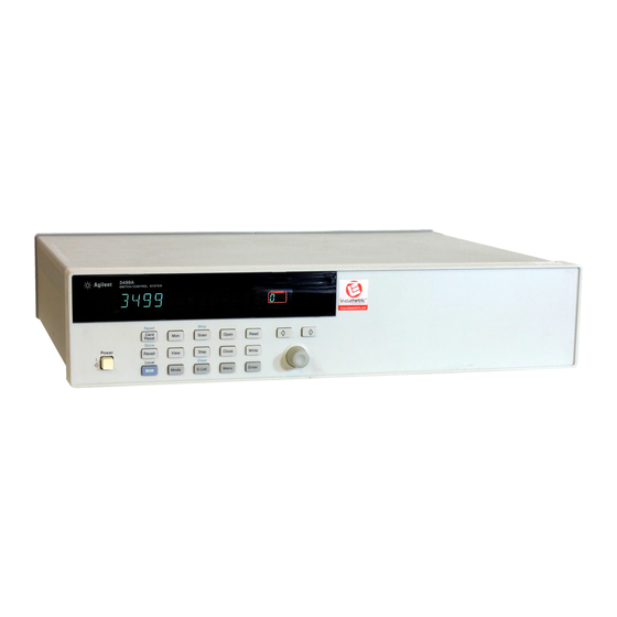
- Page 4 5. Monitor Channel/Port/Module 12. Read/Write Digital I/O Ports 6. View Menu 13. Knob 7. Mode Menu 14. Navigation Arrow Keys Note The front panel shown above is the Agilent 3499B. The 3499A and 3499C front panels are similar and have identical functionality.
- Page 5 Instrument is active on the remote interface. Instrument is in remote mode. ERROR Error queue is not empty. Scan is waiting for external trigger source. SHIFT Shift key has been pressed. Other annunciators in the display are not used in the Agilent 3499A/B/C system.
- Page 6 The Rear Panel at a Glance The figure below shows the Agilent 3499A rear panel. S l o t 1 S l o t 4 S l o t 2 S l o t 5 S l o t 3...
- Page 7 The Mini DIN Connector The rear panel mini DIN connector is used to make connections to external triggers and the built-in digital I/O port. An Agilent N2289A cable (mini DIN to D9) can be ordered to assist connections to external...
- Page 8 Use the Agilent 3499A/B/C User’s Manual (shipped with the instrument) for complete details. A PDF version is also available at www.agilent.com. If you have questions relating to the operation of the Agilent 3499A/B/C, call 1-800-452-4844 in the United States, or contact your nearest Agilent Technologies Sales Office.
-
Page 9: Table Of Contents
To Query the Firmware Revision 48 To Query the Serial Number 49 Local/Remote Control 50 Chapter 3 System Overview 51 Agilent 3499A/B/C Switch/Control System 53 Mainframes Overview 54 Firmware and Control Module Description 55 3488 Mode Differences 57 Plug-in Modules Overview 58... - Page 10 Self-Test 96 Display Control 97 Relay Cycle Counts 98 Chapter 5 Remote Interface Reference 99 Command Syntax 101 3488 Mode Command Quick Reference 102 3488 Mode Commands 104 Chapter 6 Error Messages 135 Error Messages 136 Self Test Errors 136...
-
Page 11: Chapter 1 Quick Start
Quick Start... -
Page 12: Quick Start
Quick Start This chapter describes the procedure to install the plug-in modules into an Agilent 3499A/B/C mainframe and mount the mainframe onto a system rack. The basic operations of the Agilent 3499A/B/C Switch/ Control System is also described. The chapter contents include: •... -
Page 13: To Prepare The Instrument For Use
One power cord; This User’s Manual; One Quick Reference Guide; One Tie Down Clip 03499-21002 (for Agilent 3499B only); Any plug-in modules that you ordered are delivered in separate shipping containers. 2 Connect the power cord and turn on the instrument 1. - Page 14 2. Make sure that the power source the 3499A/B/C is plugged into is energized. 3. Verify that the 3499A/B/C is turned on. Note If the 3499A/B/C DOES NOT turn on after you perform the above procedure, contact your nearest Agilent Service Center (see page 8).
-
Page 15: To Install A Module In The 3499A/B/C
These terminations are also shipped separately. For more details about terminal blocks, cables, and connections, see the Agilent 3499A/B/C User’s Manual (shipped with the instrument) or visit www.agilent.com. Module Removal To remove a plug-in module from the Agilent 3499A/B/C mainframe,... - Page 16 STEP 2 STEP 1 1. Hold the sides of the module, component side 1. Face the mainframe rear panel toward you. down, by the metal shields. 2. Select a slot in which the module is to be 2. Insert the module into the slot guides and slide installed.
-
Page 17: Basic Operation
Chapter 1 Quick Start Basic Operation Basic Operation An Agilent 3499A/B/C Switch/Control System can be easily operated from the front-panel, or programmed with SCPI commands over the remote interface. The following sections are only intended to show the basic front-panel operation. - Page 18 Chapter 1 Quick Start Basic Operation To Select a Slot and Channel When the instrument is first turned on, the display shows the model number and the slot number of the controller board. 3499 Use the knob to select a channel on the active slot. For example, with the display shown above, turning the knob to the right will select the first of the individual built-in digital I/O ports.
- Page 19 Chapter 1 Quick Start Basic Operation To Open or Close a Channel When a channel is selected, you can open or close the channel using the front panel keys. For example, with an N2260A 40-channel MUX installed in slot 1, select channel 00 as described on the previous page. OPEN Press the CLOSE key to close the channel.
- Page 20 Chapter 1 Quick Start Basic Operation To Open All Channels on a Module You can open individual channels on a module one at a time as described above. There are times, however, when it would be more expedient to open all channels on a module at once. Use the arrow keys to select the module to work with.
-
Page 21: To Rack Mount The 3499A/B/C
Chapter 1 Quick Start To Rack Mount the 3499A/B/C To Rack Mount the 3499A/B/C You can mount the Agilent 3499A/B/C on a standard 19-inch EIA rack cabinet with the optional rack-mounting kits. The instructions and mounting hardware are included with each rack-mounting kit. - Page 22 3 4 9 9 B S W I T C H / C O N T R O L S Y S T E M To Rack Mount a Single Agilent 3499B with Adapter kit 5183-7172 • A Support Shelf, part number 5063-9255, •...
- Page 23 Chapter 1 Quick Start To Rack Mount the 3499A/B/C To rack mount two Agilent 3499B’s side-by-side (or any System II instrument next to an Agilent 3499B), order: • A Support Shelf, part number 5063-9255, • And a slide kit, part number 1494-0015.
-
Page 24: Filler Panels
Adapter kit with handles, part number 5063-9223. Adapter kit To Rack Mount an Agilent 3499C Filler Panels Order filler panels to cover any unused slots in an Agilent 3499A/B/C. • 1-slot filler panel, part number 03499-00023 (option FP1) • 2-slot filler panel, part number 03499-00024 (option FP2) -
Page 25: Chapter 2 Front-Panel Operation
Front-Panel Operation... - Page 26 Front-Panel Operation The Agilent 3499A/B/C mainframes all operate the same from the front- panel. This chapter does not give a detailed description of every possible front-panel operation. It does, however, give you a good overview of the front-panel menus and front-panel keys. See the “Features and Functions”...
-
Page 27: To Power On The Instrument
GPIB address which will retain its last setting. This manual describes programming in the 3488 mode. For information about the SCPI programming mode please refer to the User’s Manual shipped with the Agilent 3499A/B/C, or visit www.agilent.com. -
Page 28: To Monitor A Channel Or A Slot
Chapter 2 Front-Panel Operation To Monitor a Channel or a Slot To Monitor a Channel or a Slot You can continuously monitor the current status of a particular switching channel, a digital I/O port, or an entire plug-in module. Monitoring from the front panel is especially useful when developing and debugging remote interface commands. - Page 29 Chapter 2 Front-Panel Operation To Monitor a Channel or a Slot Display Description The display for a multiplexer or a GP relay module. This display indicates that the monitored module is in Slot 2 and 1:0,,,,,,6,,,9, channels 10, 16, and 19 are closed. The display for a matrix module.
-
Page 30: To Use A Digital I/O Port
Chapter 2 Front-Panel Operation To Use a Digital I/O Port To Use a Digital I/O Port You can work with a digital I/O module as a port (all eight bits) or as individual bits. Reading a Digital I/O Port You can read data from the built-in 4-bit digital I/O port, or any one of the 8-bit ports on a digital I/O or multifunction module (with a DIO function). - Page 31 Chapter 2 Front-Panel Operation To Use a Digital I/O Port Writing to a Digital I/O Port You can write data to the built-in digital I/O port (numbered 090) or to one of the built-in digital I/O port bits (numbered 091 through 094), or any one of the 8-bit ports on a digital I/O or multifunction module (with a DIO function).
- Page 32 Chapter 2 Front-Panel Operation To Use a Digital I/O Port To Configure a Digital I/O Module Digital I/O modules can be configured for handshake modes and control line, flag line, and I/O line polarity. Use the Mode menu to configure digital I/O parameters.
- Page 33 Chapter 2 Front-Panel Operation To Use a Digital I/O Port 5. Press Enter to select the new mode. The display changes to show the next menu level. CONT POL POS 6. You may change other configuration parameters as desired using the same procedure.
- Page 34 Chapter 2 Front-Panel Operation To Use a Digital I/O Port 5. Turn the knob until the desired data display format (i.e., BINARY) is displayed. BINARY 6. Press Enter to make the change and return to the first level of the Mode menu.
-
Page 35: To View Instrument Errors
Chapter 2 Front-Panel Operation To View Instrument Errors To View Instrument Errors You can view errors from the front panel. This feature is especially useful when developing remote instrument control. If an error occurs, the ERROR annunciator in the display will light. Errors are stored in the error queue in the order they occur. - Page 36 Chapter 2 Front-Panel Operation To View Instrument Errors 3. Turn the knob to view other errors in the error queue (if any). 4. Press Enter to return to the first level of the View menu, the ERROR annunciator turns off. 5.
-
Page 37: Scanning Operation
Chapter 2 Front-Panel Operation Scanning Operation Scanning Operation The instrument allows you to combine an external measurement device such as a Digital Multimeter (DMM) with multiplexer channels to create a scan. During a scan, the instrument closes the configured multiplexer channels one at a time to allow a measurement to be made on that channel. - Page 38 Chapter 2 Front-Panel Operation Scanning Operation 5. Repeat step 3 and 4 to add additional channels to the list. 6. When the desired channels have been added, press the S.List key again to return to the first level of the menu. ADD TO SCAN 7.
- Page 39 Chapter 2 Front-Panel Operation Scanning Operation To View a Scan List You can view which channels are included in a scan list. This example assumes that channels 103 through 107 are included in the scan list. 1. Press the View key. The VIEW annunciator lights up and the display shows the first level menu.
-
Page 40: To Pair Two Modules Together
Chapter 2 Front-Panel Operation To Pair Two Modules Together To Pair Two Modules Together You can pair two modules together so that they operate as a single unit. The two modules to be paired must be identical (that is, they must have the same model number) and be installed in the same mainframe. -
Page 41: To Configure For External Trigger
Chapter 2 Front-Panel Operation To Configure for External Trigger To Configure for External Trigger You can use one of two modules for an external trigger. The built-in rear panel TRIG IN and TRIG OUT pair (on the control module) or the EI (External Increment) and the CC (Channel Closed) pair on a 44474A module. - Page 42 Chapter 2 Front-Panel Operation To Configure for External Trigger 4. Turn the knob to select the slot for the external trigger. Slot 0 (control module) is the built-in external trigger (available at the rear panel mini DIN connector, see page 7). If a 44474A is not installed, only slot 0 will be shown.
-
Page 43: To Configure The Power-On State
Chapter 2 Front-Panel Operation To Configure the Power-on State To Configure the Power-on State Firmware Rev 4.0 ONLY. To read your firmware version, see the procedure on page 48. For more information about firmware revisions, see “Firmware and Control Module Description” on page 55. An instrument with Firmware REV 4.0 or later can be set to power on to the reset state (see “Factory Default and Reset States”... - Page 44 Chapter 2 Front-Panel Operation To Configure the Power-on State 6. Turn the knob to select the desired memory location (i.e., 08). POWER ON 08 7. Press Enter to accept the stored state and return to the first level menu. More information about storing states is given on page 94 of this manual.
-
Page 45: To Configure The Remote Interface
To Configure the Remote Interface To Configure the Remote Interface In 3488 mode, the instrument can communicate with a computer over the GPIB interface. When shipped from the factory, the GPIB interface is selected and its address is set to “9”. - Page 46 Chapter 2 Front-Panel Operation To Configure the Remote Interface 4. Press Enter to select the interface and show the first parameter. ADDRESS 09 5. Turn the knob to set GPIB address (i.e., 07). Valid addresses range from 00 to 30. ADDRESS 07 6.
-
Page 47: To Perform A Self-Test
Chapter 2 Front-Panel Operation To Perform a Self-test To Perform a Self-test The self-test feature of the instrument provides you with a method of verifying proper instrument operation. 1. Press the Menu key. The CONFIG annunciator lights up and the first level menu is shown. -
Page 48: To Query The Firmware Revision
Chapter 2 Front-Panel Operation To Query the Firmware Revision To Query the Firmware Revision Perform the following procedure to query the 3499A/B/C firmware and revision. For a description of the firmware and hardware revisions, see “Firmware and Control Module Description” on page 55. 1. -
Page 49: To Query The Serial Number
CARD PAIR 1. Turn the knob to select “SERIAL NO”. SERIAL NO 2. Press Enter. The Agilent 3499A/B/C serial number is displayed. MY12345678 3. Press Enter again to return to the first level of the Menu menu. SERIAL NO 4. -
Page 50: Local/Remote Control
Chapter 2 Front-Panel Operation Local/Remote Control Local/Remote Control The instrument operates in two data entry modes, local and remote. In local mode, all keys on the front panel are fully functional. In remote mode, some front panel keys are locked (exception are: Local, Mon, View, Enter, the arrow keys, and the knob). -
Page 51: Chapter 3 System Overview
System Overview... -
Page 52: System Overview
System Overview An Agilent 3499A/B/C Switch/Control System is composed of a mainframe and a set of Plug-in modules. This chapter provides a typical configuration of a test system using the 3499A/B/C for switching and control, followed by a description of the three mainframes and all the Plug-in modules. -
Page 53: Agilent 3499A/B/C Switch/Control System
Chapter 3 System Overview Agilent 3499A/B/C Switch/Control System Agilent 3499A/B/C Switch/Control System The Agilent 3499A/B/C Switch/Control System provides high density and high speed switching for routing test signals to and from your DUTs (devices under test) and test instruments such as external DMMs, scopes, counters, power supplies, etc. -
Page 54: Mainframes Overview
The 3488A mode is included for backward compatibility with the legacy Agilent 3488A system. This manual documents the 3488 mode of operation. For information about the SCPI programming mode please refer to the User’s Manual shipped with your Agilent 3499A/B/C, or visit... -
Page 55: Firmware And Control Module Description
Firmware and Control Module Description Firmware and Control Module Description The Agilent 3499A/B/C and this manual support two versions of the Agilent 3499A/B/C control module and four versions of firmware. Firmware revisions and control module versions can be queried from the front-panel. - Page 56 Chapter 3 System Overview Firmware and Control Module Description Control Firmware Firmware State Plug-in module Programming Module Upgrade Version Storage Support Modes Version Needed? Stored setups Must upgrade Not Applicable are cleared if hardware and power is firmware. cycled. Stored setups Supports all Firmware Upgrade to...
-
Page 57: 3488 Mode Differences
In general, the SCPI mode of operation is recommended. All the features and functions of 3499A/B/C system and plug-in modules are supported in SCPI mode. The 3488 mode is a subset and does not support all available features. Some of the major differences in 3488 mode of operation are summarized below: •... -
Page 58: Plug-In Modules Overview
General Purpose Relay (GP) modules • Matrix modules • Digital I/O (DIO) modules • Multifunction modules • Optical Modules Note Refer to the Agilent 3499A/B/C User’s Manual (shipped with the instrument) or visit www.agilent.com for the details of the individual Plug-in modules. - Page 59 Chapter 3 System Overview Plug-in Modules Overview MUX Modules A MUX (multiplexer) module switches one signal to multiple DUTs (devices under test), or multiple signals to one device, one at a time. Example applications include capacitor leakage, connector/switch contact, and insulation resistance test systems. To expand switching capacity or build special configurations, the multiplexer switching modules can also be used with matrix or other switching modules.
- Page 60 Slots Description Number Type Required N2260A 40-Channel MUX Latching In 3488 mode, a 40-channel 2- Module wire multiplexer, switches both HI and LO inputs (200 V, 1 A) with DPST relays. N2266A 40-Channel MUX Reed non- In 3488 mode, a 40-channel 2-...
- Page 61 Chapter 3 System Overview Plug-in Modules Overview GP Modules The GP (General Purpose) relay modules often consist of independent latching or non-latching relays. They are useful for creating additional isolation between circuits, providing safety interlocks, actuating other relays or circuits, or building special topologies such as binary ladders and tree structures.
- Page 62 Chapter 3 System Overview Plug-in Modules Overview Mainframe Model Relay Module Name Slots Description Number Type Required 44471D 20-Channel GP Latching The 20 independent SPST (Single- Relay Module pole Single-throw) relays provide quality connections for low level signals. Can also switch signals up to 250V, 1A.
- Page 63 Chapter 3 System Overview Plug-in Modules Overview Matrix Modules A matrix switch is the most versatile type of system switching. Any input can be connected to any output, individually or in combination. This helps minimize the need for complex wiring, and can simplify the DUT interface.
- Page 64 Chapter 3 System Overview Plug-in Modules Overview Digital I/O Modules The digital I/O modules provide high-density digital input/output capabilities in an easy-to-control form. The independent TTL-compatible inputs and outputs make it well-suited for monitoring and controlling devices compactly and cost-effectively. Typically, the digital outputs are used to provide drive for relatively high current devices such as solenoids, relays and small motors.
- Page 65 Each separate function on a multifunction module can be operated independently. For example, an Agilent N2265A can be used as both a 4 x 4 matrix module and a 16-bit digital I/O module. The table below lists the available multifunction modules.
- Page 66 Chapter 3 System Overview Plug-in Modules Overview Optical Modules The Agilent N2280A and N2281A are optical switch modules. The table below lists the information about these three optical modules. Mainframe Model Relay Module Name Slots Description Number Type Required N2280A...
-
Page 67: Channel And Slot Addressing
The N2260A and N2266A can be only be used as a 40-channel 2-wire MUX modulein 3488 mode. b. A channel number on a matrix module is formed in Slot-Row-Column format, i.e., channel address s23 means row 2,... - Page 68 A channel number on a matrix module is formed in Slot-Row-Column format, i.e., channel address s23 means row 2, column 3 in Slot s. b. The N2260A and N2266A can only be used as a 40-channel 2-wire MUX module in 3488 mode.
- Page 69 Chapter 3 System Overview Channel and Slot Addressing Channel Addressing (snn) Plug-in Module s = Slot Number; nn = Channel Number N2270A s00, s01, s02... s07 10-Channel HIgh Voltage MUX Module N2280A s00, s01; s10, s11; s20, s21; s30, s31 Optical Switch Quad 1-to-2 MUX Module N2281A s00, s01, s02, s03;s10, s11, s12, s13...
- Page 70 Chapter 3 System Overview Channel and Slot Addressing Channel Addressing (snn) Plug-in Module s = Slot Number; nn = Channel Number 44474A Individual Bits: s00, s01, s02... s14, s15 16-Bit Digital I/O Module 8-Bit Ports: s00, s01 16-Bit Port: s02 44475A Breadboard Module 44476A...
-
Page 71: Factory Default And Reset States
Shift + Card Reset on the front-panel, or with a RESET command over the remote interface. • If a module is accidentally removed or installed while the instrument power is on, the instrument will preform a reset. 3488 Mode Defaults Item Factory Default Reset... -
Page 73: Chapter 4 Features And Functions
Features and Functions... -
Page 74: Features And Functions
Features and Functions This chapter provides details about particular functions and features of the Agilent 3499A/B/C Switch/Control System. The sections in this chapter describe the features using both the front-panel and the remote interface using SCPI commands. The examples in this chapter are general. -
Page 75: Monitoring A Channel Or A Slot
Chapter 4 Features and Functions Monitoring a Channel or a Slot Monitoring a Channel or a Slot You may need to continuously monitor the current status of a particular switching channel, a digital I/O port, or an entire plug-in module. This is especially useful when developing and debugging remote interface commands or watching for an important signal. - Page 76 Chapter 4 Features and Functions Monitoring a Channel or a Slot Example MON Display Description The display for a multiplexer or a GP relay module. This 1:0,,,,,,6,,,9, display indicates that the monitored module is in Slot 2 and channels 10, 16, and 19 are closed. The display for a matrix module.
-
Page 77: Switching A Relay Channel
Chapter 4 Features and Functions Switching a Relay Channel Switching a Relay Channel Switch modules can be used to route signals to and from your test system. This is achieved by closing or opening the relay channels on these modules. •... -
Page 78: Scanning
Scanning Scanning The Agilent 3499A/B/C can scan switching channels, digital I/O bit channels, and stored channel setups in a scan list. When a scan starts, the first channel in a scan list is closed. The channel is then opened and the next channel in the list is closed. - Page 79 Chapter 4 Features and Functions Scanning Creating a Scan List Before initiating a scan, a scan list must be set up. The instrument scans the specified channels automatically in the same order of the scan list. • The scan list is automatically cleared whenever the instrument is turned off or reset.
- Page 80 Chapter 4 Features and Functions Scanning Configuring a Scan You can use delay times to control a scan. • You can specify a delay time (from 0 to 99999.999 seconds, with 1 ms resolution) between when a channel is closed and when the next operation begins (and, if configured, a trigger out pulse is sent).
- Page 81 Chapter 4 Features and Functions Scanning Performing a Scan Once you set up a scan list and configure the scan, the actual scan can be performed. • If a scan list contains a non-existing channel, the scan cannot be performed and an error will occur. •...
- Page 82 Chapter 4 Features and Functions Scanning Using External Triggering Two control lines are provided in the rear panel mini-DIN connector: external trigger in and external trigger out. These lines can be used individually or combined to synchronize a scan list with an external instrument (such as a DMM).
- Page 83 Chapter 4 Features and Functions Scanning • Front-Panel Operation: Press Menu, use the knob to select “CONF EXT TRIG” and press Enter. Select either slot 0 (built-in external trigger) or the slot where a 44474A is installed and press Enter. Enable or disable the pair of trigger lines and press Enter. Press the Menu key again to exit the menu.
-
Page 84: Digital I/O Operation
Note For more information about a specific digital I/O module, refer to the Agilent 3499A/B/C User’s Manual (shipped with the instrument) or visit www.agilent.com. Digital I/O Configuration •... - Page 85 Chapter 4 Features and Functions Digital I/O Operation • Front-Panel Operation: Select a digital I/O module and press Mode. “CONFIG DIO” is shown in the display. Press Enter to show the second-level menu and begin the configuration. Note Be sure to select the module, not a port or bit. The options on this menu are only available when the module is selected.
- Page 86 Digital I/O Operation • Remote Interface Operation: Set the flow control parameters using the following 3488 command. This example assume a digital I/O module is installed in slot 4. ! Set the flow control to Mode OUTPUT 709; “DMODE 4,1,0,1”...
- Page 87 Chapter 4 Features and Functions Digital I/O Operation Static Mode #1 Static Mode #1 is the default mode. In this mode, data is transferred statically, there is no read or write strobe pulses or handshaking. The I/O Direction line is active and indicates direction of transfer. This is shown in the following timing diagrams.
- Page 88 Chapter 4 Features and Functions Digital I/O Operation Read or Write and Strobe Mode #3 In this mode, the I/O direction line is still used to indicate direction of transfer (input or output) but the PCTL (Peripheral control) line is used to strobe the data.
- Page 89 Chapter 4 Features and Functions Digital I/O Operation Read and Write Strobe Mode #4 Read and Write Strobe Mode #4 uses the I/O direction line as a Strobe pulse to indicate writing operations. The PCTL line is used to indicate Read operations.
- Page 90 Chapter 4 Features and Functions Digital I/O Operation Full Handshake Mode #5 Handshake Mode #5 provides a complete two wire handshake with a data direction line. During write operations, the PCTL line indicates that output data is valid; during read operations, it indicates that the digital I/O module (i.e.
- Page 91 Chapter 4 Features and Functions Digital I/O Operation R ea d O peration t1 = T im e fro m ou tp u t d isa b le to I/O lin e DATA VALID h ig h (1 0 0 s m in im u m ) DATA LINES LATCHED t2 = T im e fro m I/O lin e...
- Page 92 Chapter 4 Features and Functions Digital I/O Operation Digital Input Operation • From the front-panel, you can read data from the built-in digital I/O bits/port (numbered 090 through 094) or any one of the 8-bit ports on a digital I/O module or multifunction module. •...
- Page 93 Chapter 4 Features and Functions Digital I/O Operation Digital Output Operation • From the front-panel, you can write data to the built-in digital I/O bits/port (numbered 090 through 094) or any one of the 8-bit ports on a digital I/O module or multifunction module. •...
-
Page 94: State Storage
3499A/B/C (see page 55). • Firmware revision 1.0 must be upgraded. Please contact your nearest Agilent Technologies Office for details. • Firmware revisions 2.0 and 3.0 allow up to 10 states to be stored. Firmware revision 4.0 allows up to 40 stored states. - Page 95 SCPI mode). • Firmware revision 3.0 allows instrument operation in either SCPI or 3488 mode, not both. The mode is selected when the firmware is loaded. To Store an Instrument State Firmware revision 2.0 and 3.0 allow up to 10 stored states. Firmware revision 4.0 allows up to 40 stored states.
-
Page 96: Error Conditions
(refer to “Error Messages” on page 135). • Remote Interface Operation: In 3488 mode, the sum of the values of the possible error conditions is recorded in the error queue. For example, the returned value of “0003” means that both “Syntax Error”... -
Page 97: Display Control
Chapter 4 Features and Functions Display Control Display Control You can turn off the 3499A/B/C display (for security or increased processing speed for example). You can also write a message of up to 13 characters to the front-panel display. Note The display cannot be turned off from the front-panel. -
Page 98: Relay Cycle Counts
Chapter 4 Features and Functions Relay Cycle Counts Relay Cycle Counts The Agilent 3499A/B/C can read and track the relay cycle counts on some plug-in modules. This feature can be very useful in switching systems to track relay failures and predict system maintenance requirements. -
Page 99: Chapter 5 Remote Interface Reference
Remote Interface Reference... -
Page 100: Remote Interface Reference
It is highly recommended that you use SCPI commands (in SCPI mode) instead of 3488A commands (in 3488A mode). The SCPI commands allow you to use all the features of the Agilent 3499A/B/C and the plug-in modules. 3488 mode commands are a subset and are provided for legacy... -
Page 101: Command Syntax
Chapter 5 Remote Interface Reference Command Syntax Command Syntax Throughout this manual, the following conventions are used for command syntax for remote interface programming. • Square brackets ([ ]) indicate optional keywords or parameters. • Braces ({ }) enclose parameter choices within a command string. •... -
Page 102: 3488 Mode Command Quick Reference
Chapter 5 Remote Interface Reference 3488 Mode Command Quick Reference 3488 Mode Command Quick Reference Command Description Page Open the last channel/bit closed and close the specified channel/bit. CHAN Close one or more relays (channels/bits) on the plug-in modules. CLOSE CMON Monitor the open/close states of a plug-in module in the specified slot. - Page 103 Chapter 5 Remote Interface Reference 3488 Mode Command Quick Reference Command Description Page Query/set the SRQ mask conditions. MASK Enable/Disable GPIB I/O overlap mode. OLAP OPEN Open one or more relays (channels/bits) on the plug-in modules. Re-assert the channel/bit setup stored by the command STORE (1-10).
-
Page 104: 3488 Mode Commands
Chapter 5 Remote Interface Reference 3488 Mode Commands 3488 Mode Commands CHAN [<channel_address>] Opens the last channel/bit closed by either STEP or CHAN command and then closes the specified channel/bit. The channel_address has the form @snn, where s is the slot number and nn is the channel number. - Page 105 Chapter 5 Remote Interface Reference 3488 Mode Commands CLOSE <channel_address>[,<channel_address>,<channel_address>...] Close one or more channels on the non digital I/O (DIO) modules. It can also be used to “clear” bits on the digital I/O modules. The CLOSE command does not open any channels/bits that were previously closed.
- Page 106 Chapter 5 Remote Interface Reference 3488 Mode Commands CMON <slot> Causes the 3499A/B/C to monitor the individual card (module) in the specified slot. The slot parameter is a decimal ranging from 0 to 9 (mainframe dependent). Valid slot numbers are:...
- Page 107 Chapter 5 Remote Interface Reference 3488 Mode Commands CPAIR <slot>,<slot> Pairs two of the same (type) plug-in modules (i.e. two N2261A modules). This operation will effectively assign both modules to both slot numbers so that closing/opening/scanning a channel on either one module will perform the same operation on the respective channel on the other module.
- Page 108 Chapter 5 Remote Interface Reference 3488 Mode Commands CTYPE <slot> This query returns a string containing the module identification in the specified slot. The slot parameter is a decimal ranging from 0 to 9 (mainframe dependent). Valid slot numbers are:...
- Page 109 Chapter 5 Remote Interface Reference 3488 Mode Commands The string returned has one of the following forms: Module Returned String Empty Slot NO CARD 00000 Mainframe Built-in DIO 3499, Serial # N2260A 40CH MUX N2260A, Serial # N2261A 40CH GP...
- Page 110 Chapter 5 Remote Interface Reference 3488 Mode Commands The slot parameter is a decimal ranging from 0 to 9 (mainframe dependent). Valid slot numbers are: 3499A slots 0 through 5 3499B slots 0 through 2 3499C slots 0 through 9 The port parameter is a number that indicates where the data is to be read.
- Page 111 Chapter 5 Remote Interface Reference 3488 Mode Commands • When Slot 0 is specified, only Port 090 is valid. • If a 16-bit port is specified, data will be sent with the high or most significant byte first. The data transfer is terminated with the 3499A/B/C setting the GPIB EOI true line concurrently with the last data byte sent.
- Page 112 Chapter 5 Remote Interface Reference 3488 Mode Commands DBW <slot><port>,#I<block data> Outputs a block of data to the specified digital I/O port. When DBW is received, the 3499A/B/C will interpret the block of data to be output according to the slot/port parameters and DMODE (polarity, handshake) command.
- Page 113 Chapter 5 Remote Interface Reference 3488 Mode Commands DELAY <time in mS> Inserts a time delay between the time that a channel is closed and the time that the next command or Channel Closed pulse is executed. The delay time may be a value between 0 and 32,767 mS (32 seconds) in 1 mS increments.
- Page 114 Chapter 5 Remote Interface Reference 3488 Mode Commands DISP <ASCII character string> Writes a message (up to 13 characters) to display on the front panel of the 3499A/B/C. ASCII character string can be up to 13 characters. The characters supported by the 3499A/B/C are shown below...
- Page 115 Chapter 5 Remote Interface Reference 3488 Mode Commands DMODE <slot>[,<mode>][,<polarity>][,<EI>] Establishes the handshake mode as well as polarity of the digital I/O bits and control lines for the plug-in DIO modules. It is also used to enable/ disable the External Increment (EI) and Channel Closed (CC) pulse functions for the 44474A DIO module.
- Page 116 Chapter 5 Remote Interface Reference 3488 Mode Commands The polarity parameter is a decimal weighted sum of up to seven bits and is defined below. Definition Bit # Value Default, data lines high true (open), PCTL and PFLG low means ready, I/O Direction line 0 = Default high for ready.
- Page 117 Chapter 5 Remote Interface Reference 3488 Mode Commands DOFF Turns off the 3499A/B/C’s display. This allows the instrument to operate faster because it no longer needs to update the display. ! Turn off the display. OUTPUT 709; “DOFF” Turns on the 3499A/B/C’s display.
- Page 118 Chapter 5 Remote Interface Reference 3488 Mode Commands DREAD <slot><port>[,number of times to read] Reads the current status of the DIO modules’ ports designated as inputs. The decimal value read back is equal to the decimal sum of the bit values that are set.
- Page 119 Chapter 5 Remote Interface Reference 3488 Mode Commands • When reading the 4-bit built-in DIO port (Port 090), the decimal value will be between 0 and 15. • When reading an 8-bit port, the decimal value of the bits will be between 0 and 255.
- Page 120 Chapter 5 Remote Interface Reference 3488 Mode Commands DWRITE <slot><port>,<data>[,<data>...] Configures all or part of a DIO module to digital output ports and writes data to the DIO ports. The slot parameter is a decimal ranging from 0 to 9 (mainframe dependent).
- Page 121 Chapter 5 Remote Interface Reference 3488 Mode Commands EHALT <0 | 1> Enables or disables the stop-on-error mode. When enabled (EHALT 1), an error will lockup the GPIB interface (no GPIB communication). Default condition is disabled (EHALT 0), which allows GPIB communication after an error is discovered.
- Page 122 Chapter 5 Remote Interface Reference 3488 Mode Commands LOCK <0 | 1> Locking out the keyboard prevents the keyboard from being scanned thus permitting faster operation. LOCK 1 locks the keyboard and LOCK 0 (default) unlocks the keyboard. ! Lockout the keyboard.
- Page 123 Chapter 5 Remote Interface Reference 3488 Mode Commands OLAP <0 | 1> Suspends or releases the GPIB I/O communications. In the Overlap disabled mode (default, OLAP 0), the 3499A/B/C holds up GPIB I/O communications while it processes received messages. When Overlap is enabled (OLAP 1), the 3499A/B/C will release the GPIB as soon as the command message is received.
- Page 124 Chapter 5 Remote Interface Reference 3488 Mode Commands OPEN <channel_address>[,<channel_address>,<channel_address>...] Open one or multiple channels/bits on the plug-in modules. The channel_address has the form @snn, where s is the slot number and nn is the channel number. For all mainframes, slot 0 refers to the 3499A/ B/C control board.
- Page 125 Chapter 5 Remote Interface Reference 3488 Mode Commands RECALL <1-40> Recalls the channel/bit setup stored by the command STORE. Only relays and static Digital Outputs are recalled. This means that only those channels/bits that are closed in the stored channel setup will be closed when the channel setup is recalled.
- Page 126 Chapter 5 Remote Interface Reference 3488 Mode Commands SLIST <channel_address>[,<channel_address>,<channel_address>...] Specifies a sequence of channels to be scanned. The sequence is specified as a list of up to 85 channel addresses (relays or digital I/O lines) and/or stored setups separated by commas. Contiguous channels may be specified by entering the first channel address and the last channel address separated by a hyphen.
- Page 127 OUTPUT 709; “STEP” NEXT I SYSMODE <0|1|SCPI|HP3488A> Specifies the system mode for the Agilent 3499A/B/C Switch/Control system.The 3499A/B/C can be operated in either one of the two system modes. Specifying 0|SCPI will set the instrument to SCPI mode. Specifying 1|HP3488A will set the instrument to 3488A mode.
- Page 128 Chapter 5 Remote Interface Reference 3488 Mode Commands SREAD <slot><register> Reads data from the input port on a 44475A Breadboard in the specified slot. The data read back is in the form of a decimal number which is the sum of the binary weighted values of the bits that are high (+5 volts).
- Page 129 Chapter 5 Remote Interface Reference 3488 Mode Commands SWRITE <slot><register>,<data> Writes data to the output port on a 44475A breadboard in the specific slot. The data value is a decimal sum of the binary weighted values of the bits that are to be set high (+5 volts).
- Page 130 Chapter 5 Remote Interface Reference 3488 Mode Commands STATUS Reads the 3499A/B/C’s Status Byte and returns a decimal value that is the sum of the values of the individual bits that are set (condition is true). Weighted Value Definition End of scan sequence...
- Page 131 Chapter 5 Remote Interface Reference 3488 Mode Commands STEP Opens the last channel closed and close the next channel in the Scan List. If STEP is executed and no Scan List exists, the 3499A/B/C will generate an execution error. The 3499A/B/C uses a pointer to keep track of which channel in the Scan List is currently closed.
- Page 132 Chapter 5 Remote Interface Reference 3488 Mode Commands TEST Initiates the internal self tests and returns a number indicating the test results. A value of “+00000” returned indicates all tests have passed. Any other value indicates the instrument failed the tests as shown below:...
- Page 133 Chapter 5 Remote Interface Reference 3488 Mode Commands VIEW <channel_address> Shows the state, either open or closed of a particular channel or a DIO bit. The 3499A/B/C responds with the string “OPEN 1” if the specified channel/bit is open. If the specified channel/bit is closed, the 3499A/B/C responds with the string “CLOSED 0”.
-
Page 135: Chapter 6 Error Messages
Error Messages... -
Page 136: Error Messages
Error Messages In 3488A mode, you can query the instrument error queue when the ERROR annunciator is on. The returned decimal value is the sum of the values of the possible error conditions, as shown below: Weighted Value Error Condition Syntax Error Execution Error which includes: a. -
Page 137: Chapter 7 Application Programs
Application Programs... -
Page 138: Application Programs
Application Programs This chapter provides example programs in Visual C++, Visual BASIC and BASIC to help you develop programs for your specific application. Chapter contents include: • Visual C++ Example Program, on page 139 • Visual BASIC Example Program, on page 141 •... -
Page 139: Visual C++ Example Program
Visual C++ Example Program Visual C++ Example Program This example program is written in Visual C++ 6.0 and has been tested on a PC running WIN95/NT. The example uses the 3488 commands. As the example is currently written, the program requirements are: •... - Page 140 Chapter 7 Application Programs Visual C++ Example Program /* Create a scanlist, then set up a loop to scan through the channels two times. */ viPrintf( vi, "SLIST 100-103\n"); for ( i = 0; i < 8; i++ ) { viPrintf( vi, "STEP\n"...
-
Page 141: Visual Basic Example Program
Visual BASIC Example Program Visual BASIC Example Program This example program is written in Visual BASIC 6.0 and has been tested on a PC running WIN95/NT. The example uses the 3488 commands. As the example is currently written, the program requirements are: •... - Page 142 Chapter 7 Application Programs Visual BASIC Example Program ' Create a scanlist, then set up a loop to scan through ' the channels two times. viVPrintf(vi, "SLIST 100-103" + Chr$(10), 0) ' Create a scan list including 100 through 103. For I = 0 To 8 Call viVPrintf(vi, "STEP"...
-
Page 143: Basic Example Program
Chapter 7 Application Programs BASIC Example Program BASIC Example Program Sample programs in this section are written in BASIC 6.0 and have been tested on a UNIX workstation. Requirements: • GPIB interface selected and set to the address of 09 from the front- panel;... -
Page 145: Index
Index If you have questions realated to the operation of the Agilent 3499A/B/C or plug-in modules, call 1.800.453.4844 in the United States, or contact your nearest Agilent Technologies Sales Office. 3488 Mode Defaults 71 44475A module 3488A mode selection 27... - Page 146 CPAIR command 107 Front Panel 4 CRESET command 106 front-panel display EHALT command 121 CTYPE command 108 general description 5 EI/CC 82 cycle counts of relay 98 on/off 97 enable/disable EI/CC 41 text message 97 enable/disable trigger out pulse Front-Panel Operation 26 data display format 85 41, 83 DBR command 110...
- Page 147 N2281A module channel numbering 69 local 50 N2260A module description 66 LOCK command 122 channel numbering 67 relay type 66 LWORD 92 default setting 84 descripton 60 relay type 60 OLAP command 123 mainframes N2261A module OPEN command 124 general description 54 channel numbering 67 open/close relay channel 77 MASK command 122...
- Page 148 RESET 71, 96 slot reset 20 monitoring 75 Telephone 8 states 71 slot numbers 17 TEST command 96, 132 RESET command 125 SREAD command 128 turn on instrument 27 Rev 4.0 43 State Storage 56 turn on/off display 97 RS-232 Interface state storage connector 6 and firmware revision 94...