Table of Contents
Advertisement
Quick Links
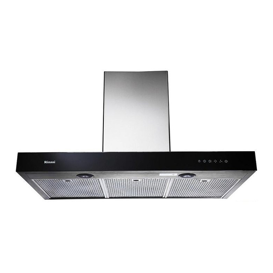
COOKER HOOD
INSTRUCTION MANUAL
NAME
PAGE
Products and accessory ...............1
Dimensions .................................2
Installation ...................................3
Caution ........................................4
Operating Instruction ..................5
Maintenance & Cleaning ............6
Trouble Shooting .........................7
Wiring Diagram ..........................8
Specification ................................9
Advertisement
Table of Contents

Related Manuals for Rinnai RH-9020A


Summary of Contents for Rinnai RH-9020A
-
Page 1: Table Of Contents
COOKER HOOD INSTRUCTION MANUAL Model:RH-9020A NAME PAGE Products and accessory ....1 Dimensions .........2 Installation ........3 Caution ........4 Operating Instruction ....5 Maintenance & Cleaning ....6 Trouble Shooting ......7 Wiring Diagram ......8 Specification ........9... -
Page 2: Products And Accessory
PART NAME Capacitor RH-9020A Electric Box Cover Electric Box Control Board Power cable Fan Blade (Right) Tube top cover Fan Blade (Left) Motor Ventilator Body Ventilator seal Oil Plate Main Tube Unit LED Light LED Back Light Glass Body Control Panel box... -
Page 3: Model:rh-9020A
Dimensions MODEL RH-9020A 210mm 896mm 507mm Hook Location A 153(6") 75mm... -
Page 4: Installation
Installation 1. Main Set Installation: The minimum distance between the cooker and the appliance is 75-90CM, anddrill holes on the wall. Screw the main set by using screw nut together. Adjust the main set till horizontal line. 75-90cm Keep it horizontal (level) 2. -
Page 5: Caution
Caution Surrounding Environment: The cooker hood should install near outdoor window. Let the exhaust air from the tube blow out easily thru the window. Alternatively, make a hole on the wall, and let the exhaust air from the aluminum tube blow out. Do not squash the (fig1) aluminum tube into the hole. -
Page 6: Operating Instruction
Operating Instruction Light Control Delay Button Turbo Speed High Speed Low Speed Power Control Button Button Control Button Control Button Button Power control button (Red light) 1. Push this button to turn on the power and power indicator light will be on. 2. -
Page 7: Maintenance & Cleaning
Maintenance & Cleaning 1. There is a fire risk if cleaning is not carried out in accordance with the instructions. 2. Be careful of the flame when cooking alcoholic food. It might cause to burn the cooker hood. 3. Make sure the ventilation is good when using glass hob and cooker hood together. 4. Wipe the cooker hood with a soft damp cloth. 5. Do not spray water directly on the cooker hood to avoid electric shock or damage to it. -
Page 8: Trouble Shooting
Trouble Shooting 1. Motor Malfunction: ● Check the electrical wiring. ● Check the power plug, On / Off switch, or fuse. ● Check the impeller. If can move by hand when power is on, means the condenser capacitor needed to be changed. ●... -
Page 9: Wiring Diagram
Wiring Diagram RH-9020A MOTOR BLACK BLACK ( BROWN) FUSE POWER WHITE WHITE ( BLUE) ELECTRIC BOARD WHITE GRAY BLACK BLUE Control Board WHITE LAMP CONDENSER YELLOW LAMP LED Back Light... -
Page 10: Specification
Specification MODEL RH-9020A DATA MATERIAL SUS304 W896xD507xH545~985mm SIZE (*Height: From button of main unit) OUTLET DIA 153mm FAN SIZE 14CMx2 MOTOR, S INSULATION VOLTAGE/FREQUENCY 240V/50Hz 1.5A LIGHT SPEED Ⅰ Ⅱ Ⅲ MOTOR SPEED 1200rpm 1800rpm 2400rpm CONSUMPTION POWER 180W 220W...