Table of Contents
Advertisement
Quick Links
Warning.......................................................
Parts Name...................................................
Installation....................................................
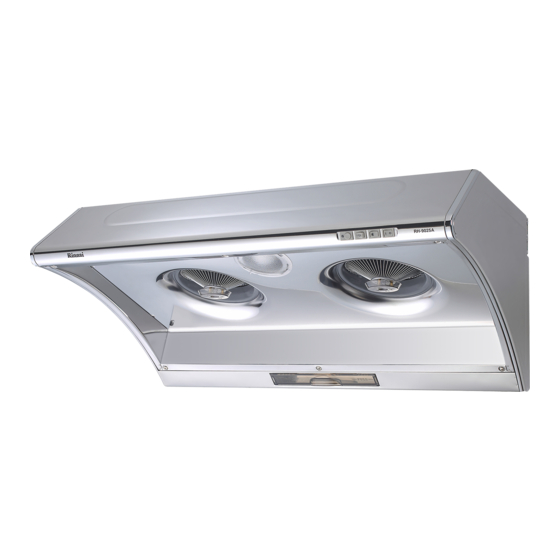
Model:RH-9025A
Installation Instruction.....................................
Caution.........................................................
Operation Instruction.......................................
Maintenance & Cleaning...................................
Trouble Shooting.............................................
Warranty & Wiring Diagram............................
COOKER HOOD
INSTRUCTION MANUAL
NAME
Products and accessory ............1
Dimensions.............................2
Instruction.............................3
Caution..................................4
Operating Instruction................5
Maintenance & & & & Cleaning...........6
Trouble Shooting......................7
Wiring Diagram.......................8
Specification............................9
PAGE
Advertisement
Table of Contents

Related Manuals for Rinnai RH-9025A


Summary of Contents for Rinnai RH-9025A
-
Page 1: Table Of Contents
COOKER HOOD INSTRUCTION MANUAL Warning………………………………………………. Parts Name…………………………………………… PAGE NAME Installation……………………………………………. Model:RH-9025A Products and accessory …………1 Installation Instruction………………………………. Caution………………………………………………... Dimensions……………………..2 Operation Instruction………………………………… Instruction………………………..3 Maintenance & Cleaning…………………………….. Caution………………………..…..4 Trouble Shooting……………………………………… Warranty & Wiring Diagram………………………. Operating Instruction…………….5 Maintenance & & & & Cleaning…..6 Trouble Shooting……………….…7... -
Page 2: Products And Accessory
PART NAME RH-9025A Electric Box Cover Capacitor Control Board Power Cable Electric Box Fan Blade (Right) Tube Top Cover Motor Fan Blade (Left) Ventilator Body Oil Plate Ventilator Seal Control Panel Kit Main Tube Unit Light Panel Body LED Light... -
Page 3: Dimensions
Dimensions MODEL RH-9025A 210mm 896mm 500mm Hook Location A 153(6") 40mm... -
Page 4: Instruction
Installation Main Set Installation: The minimum distance between the cooker and the appliance is 75-90CM, and drill holes on the wall. Screw the main set by using screw nut together. Adjust the main set till horizontal line. 75~90cm Keep it horizontal (level) 1. -
Page 5: Caution
Caution Surrounding Environment: The cooker hood should install near outdoor window. Let the exhaust air from the tube blow out easily thru the window. Alternatively, make a hole on the wall, and let the exhaust air from the aluminium tube blow out. Do not squash the aluminium tube into the hole. -
Page 6: Operating Instruction
Operating Instruction T u r b o 照 定 調 顯 調 總 Light Timing Speed(-) Monitor Speed(+) Turbo Power Instruction: : : : Power: : : : Press this button to turn on the range hood and blue indicate light up, press again to turn off all the functions and blue indicate light off. -
Page 7: Maintenance & & & & Cleaning
Maintenance & & & & Cleaning …. 1. There is a fire risk if cleaning is not carried out in accordance with the instructions. 2. Be careful of the flame when cooking alcoholic food. It might cause to burn the cooker hood. 3. -
Page 8: Trouble Shooting
Trouble Shooting 1. Motor Malfunction: Check the electrical wiring. • Check the power plug, On / Off switch, or fuse. • Check the impeller. If can move by hand when power is on, means the condenser capacitor • needed to be changed. •... -
Page 9: Wiring Diagram
Wiring Diagram RH-9025A MOTOR BLACK BLACK ( BROWN) FUSE POWER WHITE WHITE ( BLUE) ELECTRIC BOARD WHITE GRAY BLACK BLUE Control Board WHITE LAMP CONDENSER YELLOW LED Back Light LAMP Optional Equipment... -
Page 10: Specification
Specification MODEL RH-9025A DATA MATERIAL SUS304 W896xD500xH510~950mm SIZE ( ( ( ( * * * * Height: From button of main unit) Height: From button of main unit) Height: From button of main unit) Height: From button of main unit)