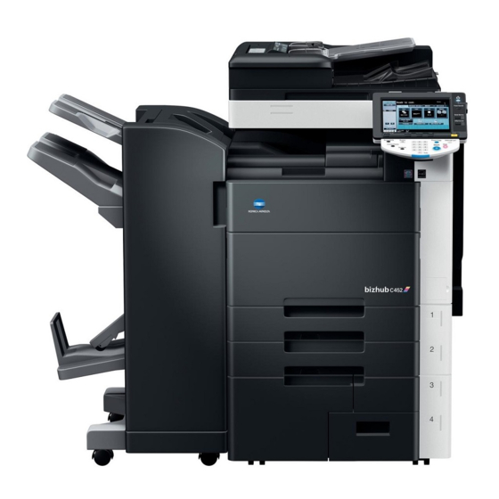
Konica Minolta BIZHUB C652 Installation Manual
Hide thumbs
Also See for BIZHUB C652:
- User manual (368 pages) ,
- Quick manual (304 pages) ,
- Manual (96 pages)
Table of Contents
Advertisement
Quick Links
<Important>
Be sure to correctly follow the procedures in order as explained in this Installation Manual.
If you do not follow the procedure in order, the image trouble may occur.
I. Outline of installation procedures
AU-101
AU-102
WT-506
AU-201
KH-101
PK-516
SD-508
When installing the machine and associated options as a system, follow the order shown on the upper.
Note:
• For the detailed installation procedures for each option, follow the instructions given in the corresponding
installation manual and perform the procedures correctly.
• Once the Power Switch is turned ON, do not turn OFF it until the installation work has been completed.
• When transporting the machine, assign an adequate number of persons to the job and follow the speci-
fied correct procedures.
(mass: approx. 221 kg (487-1/4 lb))
INSTALLATION MANUAL
Machine
SP-501
*1
MK-715
Electron system options
FS-526
/
Applied Machine:
LU-204
✱ Electron system options
LU-301
OT-503
*1
: Varies depending on the applicable marketing area.
*2
: No particular order in installation procedures.
E-1
/
*2
EK-604
*2
UK-203
*2
VI-505
*2
IC-412
FK-502
*2
MK-720
A0P0IXC010DA
A0P0-9951-01
Advertisement
Table of Contents

Related Manuals for Konica Minolta BIZHUB C652


Summary of Contents for Konica Minolta BIZHUB C652
-
Page 1: Installation Manual
INSTALLATION MANUAL Applied Machine: <Important> Be sure to correctly follow the procedures in order as explained in this Installation Manual. If you do not follow the procedure in order, the image trouble may occur. I. Outline of installation procedures AU-101 LU-204 AU-102 WT-506... -
Page 2: Accessory Parts
II. Installation space (unit: mm (inch)) IV. Accessory parts bizhub C652 + FS-526 + LU-204 Name Q’ty 1. Imaging unit (IU): Y,M,C 2376 (93-9/16) 2. Developing unit: K 1252 3. Drum unit: K (34-7/8) (49-5/16) (9-3/8) 4. User’s guide holder 5. -
Page 3: Unpacking The Machine
V. Unpacking the machine 3. Hold onto the handle of the machine and tilt the machine to the right and left. Under this condition, 1. Open the shipping box and take out the IU ship- remove the mirror mat and fixing material (lower). ping box and packaging material. - Page 4 VI. Removing protective tape, packing and 6. Position the slope as illustrated and drive nails in to fix the slope in position. other shipping materials Note: 1. Remove the protective tape and protective mate- Insert the nails in the outer holes. rial.
- Page 5 2. Remove the protective material. 5. Pull the tray 1 out and remove the protective tape from the tray. A0P0IXC045DA A0P0IXC048DA 3. Remove the reinforcement plate (four screws). 6. Pull the tray 2 out and remove the protective tape from the tray. A0P0IXC046DA 4.
- Page 6 8. Remove the protective tape from trays 3 and 4. 3. Tilt the IU to the right and, in that condition, shake it over a small stroke twice. Then, tilt the IU to the left and, in that condition, shake it over a small stroke twice.
- Page 7 6. Unlock the IU fixing lever. 9. Fix the IU in position using the IU fixing lever. A0P0IXC024DA A0P0IXC027DA 7. Keeping the IU in the level position, insert it all 10. Using the same procedure, install all IUs. the way as far as it will go. 11.
- Page 8 13. Hold the developing unit upside down and 16. Remove the protective material. remove the cap. A0P0IXC034DB A0P0IXC081DA 17. Slide out the rail from the machine. 14. Remove the protective tape. Note: Be careful that developer does not spill from the hole on the developing unit.
- Page 9 19. While aligning part A of the developing unit with 21. Fix the developing unit to the rail using the the screw hole on the rail, pass part B of the shoulder screw removed in step 18. developing unit under the rail. Part A A0P0IXC038DB 22.
- Page 10 23. Put the drum unit on the developing unit. 24. Peel off the protective sheet of the drum unit. Note: • Do not tilt the drum unit when putting it on the developing unit. (Keep the drum unit level.) • Position the drum unit so that part A of the drum unit is inserted into part B of the developing unit.
-
Page 11: Installing The Toner Cartridge
VIII. Installing the toner cartridge 26. Insert the drum unit into the machine. Note: Since cartridge is not furnished with the machine, purchase toner cartridge (of different colors) sepa- rately. 1. Open the upper front door. A0P0IXC042DA 27. Tighten one shoulder screw to secure the drum unit to the machine. - Page 12 IX. Connecting the power cord and 4. Insert the toner cartridge into the machine. Note: mounting the accessory parts Make sure that the color is same between insert- 1. Connect the power cord. ing port and the toner cartridge. A0P0IXE075DA A00JIXC019DA 2.
- Page 13 4. Attach the cap A and B furnished with the 7. Install the spacer A furnished with the machine. machine. A0P0IXC053DA A0P0IXC050DA 8. Install the spacer B furnished with the machine. 5. Install the IR cover furnished with the machine (one mounting screw furnished with the machine).
- Page 14 X. Installing the user’s guide holder XII. Adjusting touch panel Install the user’s guide holder. 1. Turn ON the Main Power Switch and then Sub Power Switch. 2. Press the accessibility key. 3. Touch “Touch Panel Adjustment.” 4. Using the panel pen, lightly touch the center of the + markers at four places on the touch panel.
-
Page 15: Adjusting Skew Feed
XIV. Adjusting skew feed 3. Measure the values “a”, “b” and “c” of the chart and the sample copy. 1. Close the reverse automatic document feeder. When measuring the value 'a', use the sample 2. Plug the power cord into the power outlet and copies which printed in step 1 and 2. - Page 16 7. Obtain the difference between the deviation of 10. When the difference of the deviation is - (minus), the chart and the deviation of the sample. turn the screw clockwise to adjust. Difference of the deviation = Y - X Note: Specifications: 0 ±...
-
Page 17: Adjusting The Document Stop Position
XV. Adjusting the document stop position 11. Press the Start key. 12. Check that “Adjustment Result” is “OK” and then 1. Display the Service Mode screen. touch “SET.” (For details of how to display the Service Mode 13. Touch “END.” screen, see the service manual.) 14. - Page 18 XVI. Setting gradation adjust 21. Press the Start key. 22. Check that “Adjustment Result” is “OK” and then 1. Set that A3 or Ledger paper is loaded in touch “SET.” the tray. 23. Touch “Main Scanning (Front).” Note: 24. Place the chart in the document feeding tray If the A3 or Ledger paper is not readily...
- Page 19 12. Touch “Copy”, and press the start key. <If A3 or Ledger paper is set in step 1> A test pattern will then be produced on the × 6. Touch “Print”, select “A3 ”, and or Ledger paper. press the start key. 13.
- Page 20 12. Touch “Copy” and press the start key. <If A4 or Letter paper is set in step 1> A test pattern will then be produced on the two ½×11 6. Touch “Print”, select “A4 ”, and or Letter papers. press the start key. 13.
- Page 21 XVII. Date/Time setting XIX. Serial number input 1. Make sure that the Service Mode screen is dis- Note: played. Serial number input is needed only for optional 2. Display the Date & Time Setting screen. devices that will be installed later. (To display the Date &...
- Page 22 XXII. Changing paper size (Tray 3 and 4) 5. Align the paper guide plate (rear) with the line marked in the bottom of the tray. Secure the 1. Turn OFF the Main Power Switch. paper guide plate (four screws). 2. Pull out the tray 3. Note: 3.
-
Page 23: Connecting Cables
XXIII. Affixing the tray labels XXV. Check through test print Affix the tray label or paper size label at the location Make operation checks using “Setting Information shown in the illustration. Print.” 1. Select the function to be used as follows: Note: Utility/Counter →... -
Page 24: Network Setting
XXVII. Network setting Make the TCP/IP address setting for the network. Note: Consult the network administrator for the setting value to be entered and make settings as required. 1. Select the function to be used as follows: Utility/Counter → Administrator Settings → Enter the Administrator Password →...