
Related Manuals for Husqvarna 155, 155 AWD


Summary of Contents for Husqvarna 155, 155 AWD
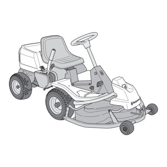
- Page 1 Operator´s manual Rider 155 Rider 155 AWD Please read these instructions carefully and make sure English you understand them before using the machine.
-
Page 3: Table Of Contents
Rider 155 and Rider 155 AWD Contents ... 1 Introduction ... 2 General ... 2 Driving and transport on public roads ... 2 Towing ... 2 Operating ... 2 Manufacturing number ... 3 Saftey rules ... 4 Explanation of symbols and decals ... 7 Safety instructions ... -
Page 4: Introduction
Introduction Congratulations Thank you for purchasing a Husqvarna ride-on mower. This machine is built for the greatest efficiency and rapid mowing primarily of large areas. Controls in one place and a hydrostatic transmission regulated by steering controls also contribute to the machine’s performance. -
Page 5: Manufacturing Number
Good Service Husqvarna’s products are sold all over the world and only in specialized retail stores with complete service. This ensures that you as a customer receive only the best support and service. Before the product is delivered, the machine has, for example, been inspected and adjusted by your retailer, see the certificate in the Service Journal in this operator’s manual. -
Page 6: Saftey Rules
These instructions are for your safety. Read them carefully. Safe operation practices for ride-on mowers IMPORTANT! This cutting machine is capable of amputating hands and feet and throwing objects. Failure to observe the following safety instructions could result in serious injury or death. General operation 1. - Page 7 IV. Service 1. Use extra care in handling gasoline and other fuels. They are flammable and vapours are explosive. a) Use only an approved container. b) Never remove gas cap or add fuel with the engine running. Allow engine to cool before refuelling.
- Page 8 Travel and transport on public roads Check the relevant road traffic regulations before driving the machine on a public road. If transporting the machine on another vehicle always use approved securing devices and make sure that the machine is securely held. Towing of the machine If your machine has a hydrostatic transmission you should only tow it very short distances at low speed...
-
Page 9: Explanation Of Symbols And Decals
EXPLANATION OF SYMBOLS AND DECALS These symbols are found on the machine and in the operator’s manual. Study them carefully so that you know what they mean. WARNING! Xxxxxxx xxxx xxxxxxxx xxx x Xxxxx xxxxxx xx. xx xxxxxxxx xxxxx xxx xx. Used in this publication to notify the reader of a risk of personal injury or death, particularly if the reader should neglect to follow instructions given in the... - Page 10 EXPLANATION OF SYMBOLS AND DECALS Placards 8009-442 – English...
-
Page 11: Safety Instructions
SAFETY INSTRUCTIONS Safety Instructions These instructions are for your safety. Read them carefully. WARNING! This symbol means that important safety instructions need to be emphasized. It concerns your safety. WARNING! THIS CUTTING MACHINE IS CAPABLE OF AMPUTATING HANDS AND FEET AND THROWING OBJECTS. - Page 12 SAFETY INSTRUCTIONS • Disengage blades when not mowing. Shut off engine and wait for all parts to come to a complete stop before cleaning the machine, removing the grass catcher, or unclogging the discharge guard. • Operate machine only in daylight or good artificial light.
-
Page 13: Personal Safety Eguipment
SAFETY INSTRUCTIONS Personal Safety Equipment WARNING! When using the machine, approved personal protective equipment (shown in illustrations) shall be used. Personal protective equipment cannot eliminate the risk of injury but it will reduce the degree of injury if an accident does happen. Ask your retailer for help in choosing the right equipment. -
Page 14: Children
SAFETY INSTRUCTIONS • Use extra care while operating machine with grass catchers or other attachments; they can affect the stability of the machine. Do not use on steep slopes. • Do not try to stabilize the machine by putting your foot on the ground. •... -
Page 15: Maintenance
SAFETY INSTRUCTIONS Maintenance WARNING! The engine must not be started when the driver’s floor plate or any protective plate for the mower deck’s drive belt is removed. Safe Handling of Gasoline To avoid personal injury or property damage, use extreme care in handling gasoline. Gasoline is extremely flammable and the vapors are explosive. -
Page 16: General Maintenance
SAFETY INSTRUCTIONS General Maintenance • Never operate machine in a closed area. • Keep all nuts and bolts tight to be sure the equipment is in safe working condition. • Never tamper with safety devices. Check their proper operation regularly. •... - Page 17 SAFETY INSTRUCTIONS • Acid in the eyes can cause blindness, contact a doctor immediately. • Be careful when servicing the battery. Explosive gases form in the battery. Never perform maintenance on the battery whe smoking or near open flames or sparks. The battery can explode and cause serious injury/damage.
-
Page 18: Transport
SAFETY INSTRUCTIONS • Never make adjustments with the engine running. • The machine is tested and approved only with the equipment originally provided or recommended by the manufacturer. Only use approved repair parts for the machine. • The blades are sharp and can cause cuts and gashes. -
Page 19: Customer Responsibilities
(if any). If a spark arrester is used, it should be maintained in effective working order by the operator A spark arrester for the muffler is available through your authorized Husqvarna dealer. English –... -
Page 20: Controls
Congratulations on your choice of a top quality product which you will enjoy for many years. This operator’s manual describes Rider 155 and Rider 155 AWD. The machines are equipped with a 15.5 horse power engine from Kohler. Rider 155 AWD also features all wheel drive. The power transmission from the engine is handled Location of the controls Ignition lock... -
Page 21: Throttle/Choke Lever
Throttle and Choke lever The engine speed is adjusted with the throttle control, and thereby also the rotation speed of the blades. The control is also used to activate the choke function. When the choke is used the engine receives a richer mixture of fuel and air, which simplifies cold start. -
Page 22: Cutting Unit
Cutting unit Rider 155 and Rider 155 AWD are equipped with a cutting unit. Combi - 1030 mm/41" See ”Maintenance \ Checking the Blades” for identification of the cutting unit. Lift lever for the cutting unit The lift lever is used to set the cutting unit in trans- port or cutting position. -
Page 23: Lever For Adjustment Of Cutting Height
Lever for adjustment of cutting height With this lever the cutting height can be adjusted to 9 different positions. Combi, IMPORTANT INFORMATION In order to obtain an even cutting height it is important that the air pressure in all four tires is the same 8,5 psi (0,6 bar). -
Page 24: Operation
IMPORTANT INFORMATION The air intake grille in the engine cover behind the driver’s seat must not be blocked by, for example, clothing, leaves, grass or dirt. Impaired cooling of the engine. Risk of major engine damage. Before starting • Read the safety instructions and information on the location and function of the controls before starting (see pages 5-14). - Page 25 Warm engine: 4. Set the throttle control midway between position 1 and 2. 5. Turn the ignition key to start position. IMPORTANT INFORMATION Do not run the starter for more than about 10 seconds at a time. If the engine does not start, wait about 60 seconds before trying again.
-
Page 26: To Start An Engine With A Weak Battery
To start an engine with a weak battery WARNING! Lead-acid batteries generate explosive gases. Keep sparks, flame and smoking materials away from batteries. Always wear eye protection when around batteries. If your battery is too weak to start the engine, it should be recharged. -
Page 27: Running
Running 1. Release the parking brake by pressing down the parking brake pedeal and then releasing it. 2. Carefully press down one of the pedals until the correct speed is reached. To drive forwards: press down pedal (1). To reverse: press down pedal (2). 3. -
Page 28: Moving Tips
4. Push in the lock button on the lift lever and lower down the cutting unit. IMPORTANT INFORMATION The service-life of the drive belts increases considerably if the engine is run at low speed when engaging the blades. For this reason do not increase the throttle until the cutting unit has been lowered to the cutting position. -
Page 29: Stopping The Engine
WARNING! Never drive the machine on ground with a slope of more than 10°. Mow slopes upwards and downwards, never across. Avoid sudden changes in direction. Operating on hills Read the Safety Instructions “Driving on Slopes” in the “Safety Instructions”. •... -
Page 30: Release Lever
Release lever The release control must be pulled out in order for the Rider to be moved when the engine is shutoff. Pro 155 AWD has one control for the front axle and one control for the rear axle. Pull the controls to their end positions. Do not use an intermediate position. -
Page 31: Maintenance
The following is a list of the maintenance which should be conducted on the machine. For the items which are not described in these instructions go to an authorised service workshop.An annual service carried out by an authorized service workshop is recommended to maintain your machine in the best possible condition and to ensure safe operation. -
Page 32: Cleaning
Cleaning and washing Clean the machine directly after use. It is much easier to wash off grass cuttings before they dry. Oily dirt can be removed using a cold degreasing agent. Spray on a thin layer. Rinse at normal water pressure. Do not direct the jet towards electrical components or bearings. -
Page 33: Dismantling Of The Machine Hoods
Dismantling of the machine hoods Engine hood The engine is accessible for servicing when the engine hood is lifted up. Tilt the seat forward, release the rubber strap under the seat, and tilt the hood backwards. Front hood Release the clip on the front hood and lift off the hood. -
Page 34: Checking And Adjusting The Steering Wires
Checking and adjustment of the steering wires The steering is controlled by means of wires. These can in time become slack, which implies that the adjustment of the steering becomes altered. Check and adjust the steering as follows: 1. Dismantle the frame-plate by releasing the screws (two on each side). -
Page 35: Adjusting The Parking Brake
Adjusting the parking brake The parking brake is adjusted as follows: 1. Loosen the locking nuts (1). 2. Tension the cable using the adjuster screw (2) until the play in the cable is taken up. 3. Tighten the locking nuts (1). 4. -
Page 36: Adjustment Of Throttle Wire
Adjusting the throttle wire If the engine does not respond as it should do when the throttle lever is moved or if the top speed is not reached, the throttle wire may need adjusting. 1. Loosen the clamping screw (by the arrow), and slide the throttle to the choke position. -
Page 37: Replacement Of Fuel Filter
Replacement of the fuel filter Replace the pipe fitted fuel filter every 100 running hours (once per season) or more frequently if it is clogged. Replace the filter as follows: 1. Fold open the engine cover. 2. Move the hose clips away from the filter. Use a pair of flat pliers. -
Page 38: Checking The Level Of The Battery Acid
5. The paper filter may be carefully tapped on a hard surface to remove dust. Do not try to wash or blow it with compressed air. 6. Insert the paper filter and check that it is correct sealed to its seat. Tighten the paper filter wing nut and install the precleaner over the paper filter. -
Page 39: Ignition System
Ignition system The engine is equipped with an electronic ignition system. Only the spark plug requires maintenance. For recommended spark plug, see chapter ”Technical data”. IMPORTANT INFORMATION Fitting the wrong spark plug type can damage the engine. Remove the ignition cable shoe and clean around the spark plug. Remove the spark plug with a 5/8"... -
Page 40: Checking The Safety System
Checking the safety system The machin is equipped with a safety system that prevents starting or driving under the following conditions: Rider 155. The engine should only be possible to start when the cutting unit is in its raised position and the hydrostat pedals are in the neutral position. -
Page 41: Main Fuse
Main fuse The fuse is located in a loose holder under the battery case cover, in front of the battery. Type: Flat-blade mounting, 15 A. Do not use any other type of fuse when replacing. A blown fuse indicates that the mounting has burnt off. -
Page 42: Fitting The Cutting Unit
WARNING! Before performing any service or adjustment checklist: 1. Engage the parking brake. 2. Place the Blade-switch in the disengaged position. 3. Turn ignition switch to “OFF” position and remove the key. 4. Make sure the blades and all moving parts have completely stopped. -
Page 43: Checking And Adjustment Of Cutting Unit's Ground Pressure
Checking and adjustment of the cutting unit’s ground pressure To achieve the best cutting results the cutting unit should follow the underlying surface without pres- sing too hard against it. The pressure is adjusted with a screw on each side of the machine. -
Page 44: Adjusting The Parallelism Of The Cutting Unit
Adjusting the parallelism of the cutting unit 1. Remove the front hood and the right-hand fender, as described on page 21. 2. Undo the nuts on the lift strut. 3. Screw out (extend) the stay to raise the rear edge of the cover. Screw in (shorten) the stay to lower the rear edge of the cover. -
Page 45: Replacing The Cutting Unit Belts
Belt replacement on the cutting unit On these cutting units with "collision-proof" blades, the blades are driven by one V-belt. Do as follows to change the V-belt: 1. Remove the cutting unit, see page 38. 2. Undo the bolt on the lift strut and the two screws on the cover. - Page 46 3. Remove the two support wheels from under the front hood. 4. Fit the support wheels on either side of the rear of the cutting unit. WARNING! Wear protective glasses when dismantling the cutting unit. The spring which tensions up the belt can go off and cause personal injury.
- Page 47 6. Place a foot on the front edge of the cutting unit near the wheel and raise the front edge of the unit to make it easier to remove the lift strut. Engage the strut in the holder. WARNING! Observe caution to avoid trapping your hand.
-
Page 48: Restoring From Service Position
9. Grasp the front edge of the cutting unit, pull out and raise into the service position. If the cylindrical bolt, which is now holding the cutting unit is removed, the cutting unit can be lifted off. Restoring from service position To leave the service position, reverse the procedures set out in “Placing in the service position”. -
Page 49: Removal Of Bioclip Plug (Combi)
Removal of BioClip plug (Combi) To change a Combi unit from BioClip function to cutting unit with rear ejection, remove the BioClip plug located under the unit with three screws. 1. Put the unit in the service position, see "Placing in the service position". -
Page 50: Lubrication
Check the engine’s oil level Check the oil level in the engine when the Rider stands horizontal with the engine switched off. Fold open the engine cover. Release the dip stick and pull out. Wipe off the oil and insert again. The dip stick must be fully screwed down. -
Page 51: Change Of Oil Filter
Change of oil filter Replace oil filter every 200 operating hours. Drain oil first using the plug on the filter base. Remove the old filter using an oil filter tool. Lightly coat rubber gasket with new oil, then install filter by turning it to the right until hand tight. -
Page 52: Lubricating The Belt Adjuster
LUBRICATION Lubricating the belt adjuster The belt adjuster should be lubricated regularly using good quality molybdenum disulphide grease*. 1 nipple from the right-hand side under the engine’s lower belt pulley, until grease is forced out. With daily use lubrication should be conducted twice a week. -
Page 53: Trouble Shooting Schedule
TROUBLE SHOOTING SCHEDULE Problem Engine will not start. Starter does not pull round engine. Engine does not run smoothly. Engine seems to have no power. Engine overheats. Battery does not charge. Machine vibrates. Uneven mowing. Procedure • Fuel tank empty. •... -
Page 54: Storage
Winter storage At the end of the season the machine should immediately be put in order for storage, also if it is going to stand idle for more than 30 days. Fuel which is left to stand for long periods (30 days or more) can leave tacky deposits which can block the carburettor and interfere with the engine. -
Page 55: Technical Data
Dimensions Length without cutting unit Width without cutting unit Height Service weight Wheel base Track Front Track Rear Tyre size Tyre pressure, front & rear Max. gradient Engine Manufacture Power Displacement Fuel Tank volume Oil synthetic Oil volume Start Noise emissions and cutting width Measured noise level Guaranteed noise level... - Page 56 When this product is worn out or no longer used it should be returned to the dealer or other appropriate body for recycling. We reserve the right to change technical specifications without prior notice. Note that no legal claims are valid on the basis of information in this manual. Use only genuine parts for repairs.
-
Page 57: Servicejournal
Work done Pre-delivery service 1. Top up battery with acid and recharge for four hours. 2. Fit steering wheel, seat and any optional equipment. 3. Adjust cutting unit: Adjust the lifting springs (the “weight” of the cutting unit should be 12-15 kg/26.5-33 lbs). Only applies to BioClip. Adjust cutting unit so that rear edge is about 2–4 mm/1/8"... - Page 58 SERVICEJOURNAL Date, mileage, stamp, sign Work done – English ´®z+R23¶5L¨...
- Page 60 115 01 81-95 ´®z+R23¶5L¨ 2005W49...