Kenwood TS-2000 Instruction Manual
All mode multi-band transceiver
Hide thumbs
Also See for TS-2000:
- Service manual (171 pages) ,
- Instruction manual (152 pages) ,
- Operation procedure (3 pages)

Related Manuals for Kenwood TS-2000


Summary of Contents for Kenwood TS-2000
-
Page 1: Instruction Manual
INSTRUCTION MANUAL ALL MODE MULTI-BAND TRANSCEIVER TS-2000 TS-2000X TS-B2000 KENWOOD CORPORATION © B62-1221-00 (K) 09 08 07 06 05 04 03 02 01 00... - Page 3 – the coming years. / c i FEATURES • All mode operation from HF to 1.2 GHz (TS-2000/ TS-B2000 Optional) amateur radio band with DSP functions. • Dual high speed Digital Signal Processing (DSP) units.
- Page 4 One or more of the following statements may be The models listed below are covered by this manual. applicable for this equipment. TS-2000 : HF/ VHF/ UHF All-mode Multi-band Transceiver FCC WARNING TS-2000X : HF/ VHF/ UHF/ 1.2 GHz All-mode This equipment generates or uses radio frequency energy.
- Page 5 • The presence of an unusual odor or smoke is often a sign of trouble. Immediately turn the power OFF and remove the power cable. Contact a KENWOOD service station or your dealer for advice.
-
Page 6: Table Of Contents
CONTENTS ALPHABETICAL FUNCTION LIST ......26 PRECAUTIONS CHAPTER 7 BASIC COMMUNICATIONS CHAPTER 1 INSTALLATION SSB TRANSMISSION ........... 28 ANTENNA CONNECTION ........1 FM TRANSMISSION ..........28 GROUND CONNECTION ........2 TX DEVIATION SELECTION ......29 LIGHTNING PROTECTION ........2 AM TRANSMISSION ..........29 DC POWER SUPPLY CONNECTION ...... - Page 7 CHANGING KEYING SPEED ......42 CHAPTER 9 REJECTING INTERFERENCE AUTO WEIGHTING ........... 42 DSP FILTERS ............55 Reverse Keying Weight ........ 42 CHANGING THE RECEIVE BUG KEY FUNCTION ........43 FILTER BANDWIDTH ........55 CW MESSAGE MEMORY ......... 43 SSB/ FM/ AM Mode ........55 Storing CW Messages ........
- Page 8 PARTIAL RESET ........... INDEX FULL RESET ............SWITCHING ANT 1/ ANT 2 ........FREQUENCY LOCK FUNCTION ......BEEP FUNCTION............DISPLAY DIMMER ............ PROGRAM FUNCTION BUTTON ......QUICK DATA TRANSFER ......... SETTING UP ............Equipment Needed ........... Connections ............. USING QUICK TRANSFER ........Transferring Data ..........
-
Page 9: Chapter 1 Installation
INSTALLATION |nstall and connect an antenna system Install and connect a DC power supply {page 2}. {page 1}. Install a ground system that satisfies DC Connect all accessories to the transceiver {pages 3, 60}. and RF grounding requirements {page 2}. Accessories include the following: •... -
Page 10: Dc Power Supply Connection
Only after the problem has been resolved, replace the blown fuse with a new one with the specified ratings. If newly installed fuses continue to blow, disconnect the power plug and contact a KENWOOD service station or your dealer for assistance. e i l... -
Page 11: Accessory Connections
3-conductor (stereo) plug. After connecting the headphones, you will hear no sound from the internal (or optional external) speaker. Microphone (MIC) Connect a microphone having an impedance TS-2000 between 250 and 600 Ω. Fully insert the TS-2000X connector, then screw the retaining ring clockwise TS-B2000 GND(STBY) until secure. -
Page 12: Receiving
YOUR FIRST QSO (HF/ 50 MHz band) Are you ready to give your TS-2000(X) a quick try? Reading these two pages should get your voice on the air in your first QSO on the HF/ 50 MHz band shortly. The instructions below are intended only for a quick guide. -
Page 13: Transmitting
This completes your introduction to the transceiver while the antenna tuner is trying to tune the TS-2000(X), but there is a great deal more to antenna. This is simply the relay switches turning ON and OFF. r With LSB, USB, or AM selected, press know. -
Page 14: Receiving
YOUR FIRST QSO (VHF/ UHF band) If your primary operating band is VHF (144 MHz) or UHF (430/ 440 MHz), the TS-2000(X) can also serve you as a powerful All-mode VHF/ UHF transceiver. The instructions below are intended only for a quick guide to get you up on the air on the VHF/ UHF band. -
Page 15: Transmitting
When you finish speaking, press [SEND] to return to receive mode. This completes your introduction on how to receive and transmit using the TS-2000(X) on a VHF/ UHF band. Refer to “OPERATING BASICS” {page 18} and the following chapters for explanations on all... -
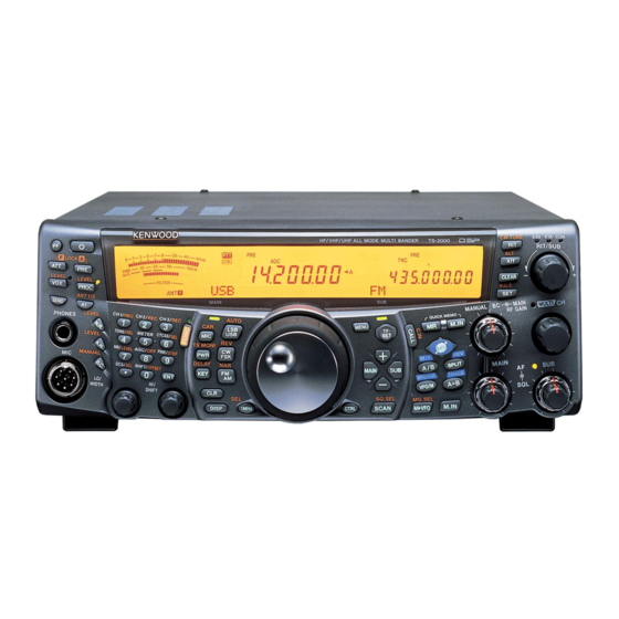
Page 16: Chapter 4 Getting Acquainted
GETTING ACQUAINTED FRONT PANEL CW TUNE 9.6k STA HF/VHF/UHF ALL MODE MULTI BANDER TS-2000 RIT/SUB F LOCK A CLEAR P.C.T MAIN AUTO MENU TX MONI DELAY MAIN SG.SEL DISP 1MHz CTRL SCAN M.IN M VFO q PF key i AT/ ANT 1/2 key... - Page 17 4 GETTING ACQUAINTED 9.6k STA CW TUNE HF/VHF/UHF ALL MODE MULTI BANDER TS-2000 RIT/SUB F LOCK A CLEAR P.C.T MAIN AUTO MENU TX MONI DELAY MAIN SG.SEL 1MHz DISP CTRL SCAN M.IN M VFO !4 Multi-purpose keypad • •/ DCS/SEL key...
- Page 18 Press to recall a call channel for the selected MHz Scan function {page 68}. operating band (HF/ 50 MHz/ 144 MHz/ 430 (440) MHz/ 1.2 GHz (TS-2000 Optional). Press @5 Tuning control [FUNC], [CALL/ C.IN] to write a new Call Channel to Turn to select the desired frequency {page 37}.
- Page 19 4 GETTING ACQUAINTED 36 35 9.6k STA CW TUNE HF/VHF/UHF ALL MODE MULTI BANDER TS-2000 RIT/SUB F LOCK A HF/VHE/UHF ALL MODE MULTI BANDER TS-2000 CLEAR P.C.T MAIN AUTO MENU TX MONI DELAY MAIN SG.SEL DISP 1MHz CTRL M.IN SCAN...
- Page 20 4 GETTING ACQUAINTED CW TUNE 9.6k STA HF/VHF/UHF ALL MODE MULTI BANDER TS-2000 RIT/SUB F LOCK A CLEAR P.C.T MAIN AUTO MENU TX MONI DELAY MAIN SG.SEL DISP 1MHz CTRL SCAN M.IN M VFO $4 RIT/SUB control %1 SUB AF control After switching the RIT or XIT function ON, turn this Press to switch the sub-receiver ON or OFF.
-
Page 21: Rear Panel
Connect your 430 (440) MHz band antenna to this !5 HF RX ANT connector connector. Connect a separate receive-only antenna for HF u ANT 1.2G (TS-2000 Optional) bands to this jack (RCA connector) {page XX}. Connect your 1.2 GHz band antenna to this connector. -
Page 22: Display
4 GETTING ACQUAINTED DISPLAY 8 12 14 16 11 13 10 9 q METER While receiving, serves as an S-meter to measure Shows the memory channel number for the main and display the received signal strength. While transceiver. If you select a channel over 99, a transmitting, serves as a power meter plus an ALC leading digit (1 or 2) appears (the memory number meter, an SWR meter, or a Speech Processor... - Page 23 4 GETTING ACQUAINTED 17 19 !7 DCS Appears when the DCS (Digital Code Squelch) of the appears when the TX Equalizer function is ON. main transceiver is ON {page 36}. appears when the RX Equalizer function of the !8 [R] main transceiver is ON {pages 41, 77}.
- Page 24 $4 + = %4 PC “+” or “–” appears, indicating which offset direction is Appears when the TS-2000/B2000 is being controlled selected for the sub-receiver. “=” appears when the by a PC {page 81}. –7.6 MHz (430MHz) or –6.0 MHz (1.2 GHz) offset is...
-
Page 25: Microphone
4 GETTING ACQUAINTED MICROPHONE The main transceiver operating frequency display. When the sub-receiver is switched ON, it shows the receive frequency for the sub-receiver. However, if you are controlling the main transceiver functions, such as RIT, XIT, or SPLIT, it is used to display the frequency information for these functions {page 45}. -
Page 26: Chapter 5 Operating Basics
HF/VHE/UHF ALL MO F LOCK A 9.6k STA CW TUNE HF/VHE/UHF ALL MODE MULTI BANDER TS-2000 RIT/SUB CLEAR MAIN F LOCK A P.C.T AUTO... -
Page 27: Selecting A Mode
Mic [DWN] to decrease the press of [LSB/ USB/ AUTO] toggles between LSB frequency. and USB mode. CW TUNE 9.6k STA HF/VHE/UHF ALL MODE MULTI BANDER TS-2000 RIT/SUB AUTO CLEAR HF/VHE/UHF ALL MO P.C.T F LOCK A... -
Page 28: Transmitting
MULTI/ CH control so that the ALC meter reflects the carrier level within the ALC zone. 1 Press [PWR/ TX MONI]. • The current transmit power appears. 9.6k STA CW TUNE HF/VHE/UHF ALL MODE MULTI BANDER TS-2000 RIT/SUB CLEAR P.C.T HF/VHE/UHF ALL MO MENU... -
Page 29: Chapter 6 Menu Setup
MENU SETUP WHAT IS A MENU? QUICK MENU Many functions on this transceiver are selected or Because the number of functions this transceiver configured via a software-controlled Menu, rather provides is extraordinary, there are numerous items in than through the physical controls of the transceiver. each Menu. -
Page 30: Menu Configuration
5 MENU SETUP MENU CONFIGURATION i t c i n i u l l – t i l x i f y l l x i f i r r i n i i n i i n i i n i... - Page 31 5 MENU SETUP i t c – z i l z i l z i l t l i t l i f n i l e l i i f i l – i f i l i f i l i f i l i f i l i f i l...
- Page 32 5 MENU SETUP i t c y t i c t i t f i y t i – & – t l i f...
- Page 33 5 MENU SETUP i t c > t i l i l p i l p ) f f v i t...
-
Page 34: Alphabetical Function List
5 MENU SETUP i t c – s l l s l l s l l s l l ALPHABETICAL FUNCTION LIST i t c i t c i f i l z i l i f i l z i l i f i l t l i f i f i l... - Page 35 5 MENU SETUP i t c i t c ) f f t l i f s l l s l l...
-
Page 36: Chapter 7 Basic Communications
BASIC COMMUNICATIONS SSB TRANSMISSION FM TRANSMISSION SSB is the most commonly-used mode on the HF FM is a common mode for communicating on VHF or Amateur bands. Compared with other voice modes, UHF frequencies. Many amateur radio operators use SSB requires only a narrow bandwidth for their portable radios and mobile transceivers in FM communications. -
Page 37: Tx Deviation Selection
6 BASIC COMMUNICATIONS AM TRANSMISSION NARROW BANDWIDTH FOR FM Each mode used on the HF Amateur bands has its When operating in FM mode, you can select wide or own advantages. Although long distance DX narrow bandwidth operation. The table below shows contacts may be less common while using AM, the the RX IF filter bandwidth and TX deviation superior audio quality characteristic of AM operation... -
Page 38: Cw Transmission
6 BASIC COMMUNICATIONS CW TRANSMISSION AUTO ZERO-BEAT Use Auto Zero-beat before transmitting to tune in a CW operators know that this mode is very reliable CW station. Auto Zero-beat automatically and exactly when communicating under worst conditions. It may matches your transmit frequency with the station you be true that newer digital modes rival CW as being are receiving. -
Page 39: Chapter 8 Enhanced Communications
ENHANCED COMMUNICATIONS TF-SET (TRANSMIT FREQUENCY SET) SPLIT-FREQUENCY OPERATION TF-SET allows you to temporarily switch your Usually you can communicate with other stations transmit frequency and receive frequency. Canceling using a single frequency for receiving and this function immediately restores the original transmitting. -
Page 40: Fm Repeater Operation
In addition, some repeaters must receive a tone from the transceiver before it allows access. Repeaters are available on the 29, 50, 144, 430 (440) MHz, and 1.2 GHz bands (TS-2000/ TS-B2000 Optional). For further information, including repeater frequencies, consult your local repeater reference. -
Page 41: Transmitting A Tone
7 ENHANCED COMMUNICATIONS TRANSMITTING A TONE Some FM repeaters require the transceiver to transmit a subaudible tone to prevent other repeaters on the same frequency from locking each other up. The required tone frequency differs among repeaters. Repeaters also differ in their requirements for either continuous or burst tones. -
Page 42: Automatic Repeater Offset
7 ENHANCED COMMUNICATIONS AUTOMATIC REPEATER OFFSET AUTOMATIC SIMPLEX CHECK (ASC) This function automatically selects an offset direction, ASC functions only when you have programmed an according to the frequency that you select on the offset on the 29, 50, 144, 430 (440) MHz or 1.2 GHz 144 MHz band. -
Page 43: Tone Freq. Id Scan
7 ENHANCED COMMUNICATONS FM CTCSS OPERATION You may sometimes want to hear calls only from specific persons. When using FM mode, the Continuous Tone Coded Squelch System (CTCSS) allows you to ignore (not hear) unwanted calls from other persons who are using the same frequency. A CTCSS tone is subaudible and is selectable from among the 38 standard tone frequencies. -
Page 44: Fm Dcs Operation
7 ENHANCED COMMUNICATIONS You will hear calls only when the selected code is FM DCS OPERATION received. To answer the call, press [SEND] or press and hold Mic [PTT], then speak into the microphone. Digital Code Squelch (DCS) is another FM application which allows you to ignore (not hear) Skip steps 7 to 9 if you have already programmed the unwanted calls. -
Page 45: Communicating Aids
COMMUNICATING AIDS Using 1 MHz Steps RECEIVING SELECTING YOUR FREQUENCY Pressing [+]/ [–] on the front panel changes Amateur bands. You can also use the MULTI/ CH In addition to turning the Tuning control or pressing control to change the operating frequency in steps Mic [UP]/[DWN], there are several other ways to of 1 MHz. -
Page 46: Fine Tuning
Receiving high-speed CW mode for all bands and AM mode for the 144 MHz/ 430 (440) MHz/ 1.2 GHz (Optional) bands. Unlike other transceivers, the TS-2000’s digital AGC circuit allows you to adjust the time constant from Equalizing VFO Frequencies (A=B) slow to fast in 20 steps, where 1 is the slowest and 20 is the fastest. -
Page 47: Transmitting
8 COMMUNICATING AIDS Delay Time TRANSMITTING If the transceiver returns to receive mode too VOX (VOICE-OPERATED TRANSMIT) quickly after you stop speaking, your final word may not be transmitted. To avoid this, select an VOX eliminates the necessity of manually switching appropriate delay time that allows all of your to the transmit mode each time you want to transmit. -
Page 48: Speech Processor
8 COMMUNICATING AIDS SPEECH PROCESSOR XIT (TRANSMIT INCREMENTAL TUNING) The Speech Processor levels out large fluctuations in Similar to RIT, XIT provides the ability to change your transmit frequency by ±20.00 kHz in steps of 10 Hz your voice while you speak. When using SSB, FM, or AM mode, this leveling action effectively raises the without changing your receive frequency. -
Page 49: Customizing Transmit Signal Characteristics
8 COMMUNICATING AIDS CUSTOMIZING TRANSMIT SIGNAL CHARACTERISTICS Amplitude The quality of your transmitted signal is important, Conventional Formant pass regardless of which on-air activity you pursue. However, it is easy to be casual and overlook this fact High boost since you don’t listen to your own signal. The following sub-sections provide information that will help you tailor your transmitted signal. -
Page 50: Cw Break-In
8 COMMUNICATING AIDS CHANGING KEYING SPEED CW BREAK-IN The keying speed of the electronic keyer is fully Break-in allows you to transmit CW without manually adjustable. Selecting the appropriate speed is switching between transmit and receive modes. Two important in order to send error-free CW that other types of Break-ins are available: Semi Break-in and operators can copy solidly. -
Page 51: Bug Key Function
8 COMMUNICATING AIDS 4 Begin sending using the keyer paddle. BUG KEY FUNCTION • The message you send is stored in memory. The built-in electronic keyer also can be used as a semi-automatic key. Semi-automatic keys are also known as “Bugs”. When this function is ON, dots are generated in the normal manner by the electronic keyer. -
Page 52: Changing Sidetone Volume
8 COMMUNICATING AIDS • While playing back the messages, you can 2 Press [+] to select ON. also adjust the keyer speed by pressing 3 Press [MENU] to store the settings and exit the [KEY/ DELAY] and turning the MULTI/ CH Menu mode. -
Page 53: Chapter 9 Sub-Receiver
1.2 GHz) bands with the main tranceiver. To control all the available functions of the sub- Since the TS-2000 also has a built-in TNC, you can receiver, press [SUB] to transfer the controls and assign the sub-receiver to monitor the local DX transmission capability to the sub-receiver. -
Page 54: Adjusting The Audio Frequency (Af) Gain
PWR functions are held for momentarily. audio level and counterclockwise to decrease the level. i t c <TS-2000/ DIAGRAM 46-02> Note: Peak Hold readings cannot be deactivated. SELECTING A MODE FOR THE SUB-RECEIVER First, confirm that the “CTRL” icon is on the SUB band display. -
Page 55: Attenuator
4 SUB-RECEIVER 144 MHz and 430 (440) MHz bands, activating the TRANSMITTING attenuator function for the sub-receiver also causes the function to switch ON for the same band of the First, confirm that the “PTT” icon is on the SUB band main transceiver. -
Page 56: Automatic Simplex Check (Asc)
AUTOMATIC SIMPLEX CHECK (ASC) You can also use ASC functions on the 144 MHz and 430 (440) MHz bands of the sub-receiver. While using a repeater, ASC periodically monitors the strength of the uplink frequency to check the signals. Press and hold [TF-SET] until “[R]” appears on the SUB band display. -
Page 57: Chapter 9 Specialized Communications
SPECIALIZED COMMUNICATIONS Note: PACKET RADIO Unlike a TNC, a Multimode Communications Processor (MCP) serves as a communications interface in several digital modes Packet is a unit of data transmitted as a whole from such as Packet, RTTY, and AMTOR. You can cause it to switch one computer to another, on a network. -
Page 58: Preparation
7 SPECIALIZED COMMUNICATIONS If you are using an external TNC or MCP, proceed PREPARATION with the subsequent steps. 1 Connect the transceiver to your personal 11 Following the instructions provided with your TNC computer (via an external TNC or MCP if desired). or MCP, enter the calibration mode so that you •... -
Page 59: Radio Teletype
7 SPECIALIZED COMMUNICATIONS 7 Following the instructions provided with your MCP, RADIO TELETYPEWRITING (RTTY) enter a command from your computer to select transmit mode. RTTY is the data communications mode with the longest history. It was originally designed for use with •... -
Page 60: Amtor/Pactor/Clover/G-Tor
7 SPECIALIZED COMMUNICATIONS AMTOR/ PacTOR/ CLOVER/ G-TOR/ PSK31 SLOW SCAN TV/ FACSIMILE Besides Packet and RTTY, digital modes which have Slow-scan Television (SSTV) is a popular application been used among hams include AMTOR, PacTOR, for transmitting still images over the air, from one CLOVER, G-TOR, and PSK31. -
Page 61: Dx Packetclusters Tune
7 SPECIALIZED COMMUNICATIONS DX PACKETCLUSTER TUNE SATELLITE OPERATION DX PacketCluster is a packet network which consist It was in December of 1961 when the first Amateur of nodes and stations who are interested in DXing satellite named OSCAR I was launched. OSCAR and contesting. - Page 62 7 SPECIALIZED COMMUNICATIONS 1 Press [SATL] to select Satellite mode. • The default downlink (435.9 MHz) and uplink (145.9 MHz) frequencies appear. • “TRACE”, “R”, and “SATL” appear to indicate the current selections. <DISPLAY> 2 On VFO A, tune to the downlink frequency of the satellite.
-
Page 63: Chapter 9 Rejecting Interference
DSP FILTERS KENWOOD digital signal processing (DSP) technology is used for the functions described in this section. Using DSP filtering, the TS-2000 frees you from installing many analog filters for each operating mode. Additionally, you can control the bandwidth, cancel the multiple jamming beat, and reduce the 4 To return the display to the current operating noise level using DSP filtering technology. -
Page 64: Beat Cancel (Ssb/ Fm/ Am)
9 REJECTING INTERFERENCE Press [FUNC], [B.C./ MANUAL], then turn the NOTCH FILTER (SSB) MANUAL BC control to select the single Beat Auto Notch filter automatically locates and attenuates Cancel frequency manually. You can select the any single interfering tone within the receive pass beat cancel frequency from approx. -
Page 65: Noise Blanker
9 REJECTING INTERFERENCE NOISE BLANKER ATTENUATOR Noise Blanker was designed to reduce pulse noise The Attenuator reduces the level of received signals. such as that generated by automobile ignitions. This function is useful when there is strong Noise Blanker does not function in FM mode. interference from adjacent frequencies. -
Page 66: Chapter 10 Memory Features
STORING DATA IN MEMORY MEMORY CHANNELS There are 2 methods used for storing transmit/receive The TS-2000 provides you with 300 memory frequencies and associated data in memory channels channels, numbered 00 to 299, for storing operating 00 to 289. Use either method, depending on the frequency data, modes and other information. -
Page 67: Split-Frequency Channels
10 MEMORY FEATURES Split-Frequency Channels MEMORY RECALL AND SCROLL 1 Press [A/B] to select VFO A or VFO B. There are two modes which allow you to retrieve frequencies and associated data that you stored in a • “tA” or “tB” appears to show which VFO memory channel: Memory Recall and Memory Scroll. -
Page 68: Memory Scroll
If you access Menu No. 07 and select ON, you can also use a memory channel and a VFO together for this operation, as <TS-2000/Diagram 60-01> follows: • RX: Memory channel... -
Page 69: Memory Transfer
10 MEMORY FEATURES MEMORY TRANSFER Memory VFO Transfer After retrieving frequencies and associated data from Memory Recall mode, you can copy the data to the VFO. This function is useful, for example, when the frequency you want to monitor is near the frequency stored in a memory channel. -
Page 70: Storing Frequency Ranges
10 MEMORY FEATURES STORING FREQUENCY RANGES MEMORY CHANNEL LOCKOUT Memory channels 290 to 299 allow you to store You can lock out memory channels that you prefer frequency ranges for VFO tuning and Program Scan. not to monitor during Memory Scan. Memory Program Scan is described in the next chapter. -
Page 71: Memory Channel Lockout
10 MEMORY FEATURES MEMORY CHANNEL NAME Available characters using a DTMF Mic You can assign a name to each memory channel. A maximum of 7 alpha-numeric characters can be stored. 1 Press [M.IN] to enter Memory Scroll mode. 2 Turn the MULTI/ CH control, or press Mic [UP] or [DWN] to select a memory channel. -
Page 72: Quick Memory
[SUB] {page 63}. 4 The current Memory Group appears in a larger t l i f font. <TS-2000/ Diagram 64-03> 5 Press a numeric key to change the selected Group number. The newly selected Group number appears in a larger font. -
Page 73: Temporary Frequency Changes
10 MEMORY FEATURES You can store data in the Quick Memory only when QUICK MEMORY VFO TRANSFER using VFO frequencies for both transmitting and This function copies the contents of the recalled receiving. memory channel to the VFO. 1 Select the frequency, mode, etc. on the main 1 Recall a Quick memory channel. -
Page 74: Chapter 11 Scan
SCAN Scan is a useful function for hands-off monitoring of • Program Scan your favorite frequencies. By becoming comfortable By programming the start and end frequency in with all types of Scan, you will increase your Memory channels 290 ~ 299 {page 62}, you can operating efficiency. -
Page 75: Program Scan
11 SCAN 11 SCAN 5 Press [SCAN/ SG.SEL] to start the Program PROGRAM SCAN Scan. Program Scan monitors the range between the • To quickly move towards a desired frequency start and end frequencies that you have stored in while scanning, turn the Tuning control or the Conventional memory channels 290 to 299. -
Page 76: Scan Hold
11 SCAN 3 Press [VFO/ M] to recall the memory channel [CLR]. (290 - 299) for which you want to specify the scan Note: slow down frequencies. You cannot change the MHz Scan speed in FM mode. 4 Press [+] or [–] to confirm the start or end You cannot change the scan speed on the sub-receiver. -
Page 77: Using Visual Scan
11 SCAN 4 Press the desired Group number ([0] to [9]) using ALL-CHANNEL SCAN the numeric keypad. The selected Group number Use the following procedure to scan all the memory appears in a larger font. channels that contain frequency data in sequence, Note: You can select only one of 10 groups (0 to 9) for each ignoring the Memory Group number. -
Page 78: Call Scan
A Call channel can be stored for each operating band, such as HF, 50 MHz, 144 MHz, 430 (440) MHz and 1.2 GHz (TS-2000 Optional) bands. You can monitor one of these Call channels and the current operating frequency alternatively. - Page 79 11 SCAN < This page is intesionally left blank at this moment. Additional Visual Scan explanation may be flooded over to this page>...
-
Page 80: Chapter 12 Operator Conveniences
ALT (Auto Lock Tuning) APO (Auto Power OFF) The ALT (Auto Lock Tuning) allows the transceiver to You can set the TS-2000 to switch OFF automatically adjust the center receiving frequency automatically if no keys or controls are pressed or adjusted for a when you operate on the 1.2 GHz band in FM mode. -
Page 81: Auto Mode
12 OPERATOR CONVENIENCES high (more than 10:1), an alarm (“SWR” in morse code) sounds and the internal tuner is bypassed. Before attempting to tune again, adjust the antenna system to lower the SWR. 5 See the display and check that tuning has successfully finished. - Page 82 12 OPERATOR CONVENIENCES 1 Press and hold [USB/ LSB/ AUTO] + The next table is an example of adding 4 frequency POWER ON. points into memory. With this setup, the transceiver selects AM mode below 1.62 MHz, CW mode from 2 Press [+] or [–] to select the band to add the 1.62MHz to 2.0 MHz, LSB mode from 2.0 MHz to frequency points.
-
Page 83: Call Channel
12 OPERATOR CONVENIENCES The transceiver also generates the following warning, DISPLAY confirmation, and malfunction beeps. BRIGHTNESS The brightness of the LCD display can be selected from OFF, and 1 to 4 by accessing Menu No. 00. c t i d i l 1 Press [MENU], then turn the MULTI/ CH control to access Menu No. - Page 84 LINEAR AMPLIFIER CONTROL 9 Press [M.IN] to store the data into memory. When you connect an external HF linear amplifier to the TS-2000(X) transceiver using the REMOTE Transmitting DTMF Memory Channel Data connector, select 1 (fast switching/ 10 ms delay) or 2...
-
Page 85: Lock Functions
“MICROPHONE PF KEYS” to this PF key, accessing Menu No. 51A. The Lock All function disables all the keys and controls on the TS-2000 transceiver, except [FUNC], [PRE/ LOCK A], Mic [PTT] and [FUNC], RISE TIME OF CW [ATT/ F LOCK] . - Page 86 Squelch Hang Time SEPERATE SPEAKER OUTPUT You can adjust the squelch hang time to The TS-2000 has 2 independent receivers and is continuously monitor unstable signals. When the capable of receving 2 different frequencies at the signal is temporarily weaker than the S-meter same time.
- Page 87 TRANSVERTER If you have a transverter that converts the TS-2000 operating frequencies to other frequencies, you can use this TS-2000 transceiver as a transverter exciter. Consult the instruction manual that came with the transverter for interfacing to the TS-2000.
-
Page 88: Quick Data Transfer
DSP-100. Note: USING QUICK TRANSFER If you always use the TS-2000 (X) for receiving only, activate TX Inhibit function, accessing Menu No. 54 to When connecting with another TS-2000(X), TS-570, avoid unintentional transmission. -
Page 89: Computer Control
12 OPERATOR CONVENIENCES COMPUTER CONTROL REPEATER FUNCTION (K-type ONLY) By connecting this transceiver to a computer, you can change the computer into an electronic console from This transceiver is capable of receiving signals on which you can remotely control functions of the one band and retransmitting them on another band. - Page 90 TS-2000 transceiver from a location outside your home or vehicle. Note: To remotely control the TS-2000, you can also use a handheld transceiver which does not have a remote control function, but a DTMF function. You must, however, manually send DTMF tones for control code strings.
- Page 91 (an external remote control unit), the following the TS-2000(X) transceiver from a seperate location. procedure shows how to set up your TS-2000 as a Since the TS-2000(X) transceiver has an independent “Transporter” at a base station and the TM-D700A as VHF and UHF sub-receiver in addition to the main a “Commander”.
- Page 92 After pressing Mic [#], press Mic [0] to [9] to enter a frequency or memory channel number. After setting up both the TS-2000 (Transporter) and When Mic [0] is pressed, the Commander shows the the TM-D700A (Commander) for Sky Command II+ current settings of the HF transceiver: operation, press Mic [0] on the Commander.
- Page 93 Sky Command II+. c t i Select 1200 bps for TH-D7A (9600 bps can be used only when you use another TS-2000 as a “Commander”). 7 Access Menu No. 46 and select SUB. 8 Select a 144 MHz band frequency in FM mode on...
- Page 94 12 OPERATOR CONVENIENCES i t c c t i l l a c t i i l p f - t c t i c t i l l a l l a c t i After pressing [ENT], you can use these keys as numeric keys to enter a frequency or memory channel number.
- Page 95 TS-2000 (Transporter). v i t 2 Access Menu No. 62C to select the same CTCSS tone frequency that you selected for the TS-2000 (Transporter). 3 Access Menu No. 62D and select the same communication speed that you selected for the TS-2000 (Transporter).
- Page 96 “Transporter”. This transceiver is connected to the TS-2000(X) via the RS-232C port, EXT SP jack, and Mic connector of the base station and the other TH-D7A or TM-D700A transceiver works as a “Commander”.
- Page 97 12 OPERATOR CONVENIENCES 6 Repeat steps 3 to 5 to record a message on DRU-3A DIGITAL RECORDING UNIT another channel. (OPTIONAL) Note: Pressing the [POWER] switch cancels recording in progress and clears the memory channel. The optional DRU-3A unit allows you to record a voice message on up to 3 channels.
- Page 98 12 OPERATOR CONVENIENCES Sending Messages 1 Select SSB, FM, or AM. • Use the same mode for transmitting and receiving. 2 Press [VOX/ LEVEL] to switch VOX ON or OFF. • If you switched VOX ON, skip step 3. 3 Press [SEND], or press and hold Mic [PTT]. 4 Press [1/ CH1/REC], [2/ CH2/REC], or [3/ CH3/REC], depending on which channel you want to use.
- Page 99 12 OPERATOR CONVENIENCES • Menu numbers and their settings are announced VS-3 VOICE SYNTHESIZER (OPTIONAL) with a short pause (200 ms) between the menu number and the setting. Install the optional VS-3 unit to use this function. Each time you change the transceiver mode such as Note: If operating a key or a control changes the contents of the VFO A/B or Memory Recall, the transceiver display while an announcement is in progress, the announcement...
-
Page 100: Initial Settings
If your transceiver seems to be malfunctioning, resetting the microprocessor default settings may resolve the problem. There are 2 levels of resetting the microprocessor of the TS-2000(X): partial reset and full reset. INITIAL SETTINGS For each VFO, the factory defaults for the operating frequency and mode are as follows: •... - Page 101 Straight cable COMPATIBLE TRANSCEIVER When transferring data to or from another TS-2000, TS-570, or TS-870S, directly connect the two transceivers using the COM connectors. When transferring data to other KENWOOD transceivers, use the optional IF-232C interface unit. Connect the IF-232C to the ACC 1 connector located on the compatible transceiver.
-
Page 102: Antenna Tuner
Note: Do not share a single power supply between the transceiver and the RTTY equipment. Keep as wide a separation as possible between the transceiver and the RTTY equipment as practical to reduce noise-pickup by the transceiver. power supply TS-2000 ACC 2 Personal computer/ dumb terminal LINEAR AMPLIFIER Connect an external transmit power amplifier to the REMOTE connector. - Page 103 Microphone audio input • Connect to TNC or MCP transmit data pin for digital operation. Shield for pin 11 PTT control (in parallel with MIC jack) for connecting a footswitch or other external controller Black TS-2000 TNC/MCP PS-53 Personal computer dumb terminal...
-
Page 104: Installing Options
INSTALLING OPTIONS You will require a philips screw driver when installing VS-3 VOICE SYNTHESIZER UNIT the optional units. CAUTION: SWITCH OFF THE POWER AND UNPLUG THE DC POWER CABLE BEFORE BEGINNING INSTALLATION. REMOVING THE BOTTOM CASE 1 Remove the bottom case (10 screws). When installing the optional DRU-3A or VS-3 unit, 2 Locate the VS-3 connector. - Page 105 14 INSTALLING OPTIONS MB-430 MOBILE BRACKET RC-2000 REMOTE PANEL CAUTION: SWITCH OFF THE POWER AND UNPLUG THE DC POWER CABLE BEFORE BEGINNING INSTALLATION. 1 Remove the bottom case (10 screws). 2 Locate VS-3 connector. 3 Hold the VS-3 unit with the component side facing up, and insert the VS-3 connector into the VS-3 connector.
- Page 106 You may return your transceiver for service to the CLEANING authorized KENWOOD dealer from whom you purchased it or any authorized KENWOOD service The buttons, controls and case of the transceiver are center. A copy of the service report will be returned likely to become soiled after extended use.
-
Page 107: Troubleshooting
After switching ON the The backup lithium battery voltage is Have a new battery installed by your transceiver, too low. dealer or at a KENWOOD Service “14.000.00 MHz USB” Center. appears and all data is lost; without doing Full Reset. - Page 108 16 MAINTENANCE No signals are 1 The SQL control is fully clockwise. 1 Turn the SQL control counterclockwise. received or receive sensitivity seems 2 Press [ATT] to switch OFF function. 2 The Attenuator function is ON. poor. [SEND] was pressed, and the 3 Press [SEND] to return to receive transceiver is now in transmit mode.
- Page 109 16 MAINTENANCE 1 Check the antenna connection. Attempting to 1 The antenna was not connected Correct as necessary. transmit results in the correctly. “HELLO” message 2 Reduce the SWR of the antenna 2 The impedances of the antenna appearing and the system.