
Related Manuals for Kenwood RC-2000


Summary of Contents for Kenwood RC-2000
-
Page 1: Instruction Manual
INSTRUCTION MANUAL MOBILE CONTROLLER RC-2000 KENWOOD CORPORATION © B62-1292-10 (M) 09 08 07 06 05 04 03 02 01 RC-2000 MOBILE CONTROLLER... - Page 2 SUPPLIED ACCESSORIES e l i l l o ) t f ) t f ) t f ) t f t l i f ) l l 2 parts are used. CONVENTIONS FOLLOWED IN THIS MANUAL The writing conventions described below have been y t i followed to simplify instructions and avoid unnecessary –...
-
Page 3: Table Of Contents
CHAPTER ABOUT THIS MANUAL BEFORE YOU BEGIN ... 1 PREPARATION (Pages 2 ~ 6) ... 1 QUICK START (Page 7) ... 1 KEYS AND CONTROLS (Pages 8 ~ 12) ... 1 CYCLING THE KEY GROUPS (Pages 13 ~ 30) ... 1 SATELLITE MODE (Pages 31 ~ 33) ... - Page 4 MAINTENANCE GENERAL INFORMATION ... 52 SERVICE ... 52 SERVICE NOTE ... 52 CLEANING ... 52 CHAPTER SPECIFICATIONS RC-2000 MOBILE CONTROLLER ... 53 EXTERNAL SPEAKER ... 53 CHAPTER APPENDIX RESETTING MEMORY DATA ... 54 DEMONSTRATION MODE ... 54 CONFIGURING THE AUTO MODE FREQUENCY TABLE ... 54 CONCERNING THE TM-D700A/E PANEL ...
-
Page 5: Chapter 1 About This Manual
When you are getting ready to install the brackets and cables, read this chapter. QUICK START (Page 7) If you are operating the RC-2000 for the first time, read this chapter and follow the instructions for a trial run. KEYS AND CONTROLS (Page 8 ~ 12) -
Page 6: Preparation
(7 m/ 23.1 ft), the microphone extension cable (5 m/ 16.5 ft), a cable for the speaker (5 m/ 16.5 ft), a cable to the RC-2000 (5 m/ 16.5 ft), and coaxial cable(s) to the antenna (not supplied in this package). Make sure all cable lengths are adequate before installing the brackets. -
Page 7: Front Panel Installation
FRONT PANEL INSTALLATION 1 Assemble the mounting brackets using the 2 supplied hexagon SEMS screws and the 2 flat washers. • Do not completely tighten the screws in this step. SEMS screw 2 Peel off the paper backing from the base of the bracket. -
Page 8: Speaker And Mic Cable Installation
SPEAKER AND MIC CABLE INSTALLATION Connect the speaker extension cable plug to the EXT.SP1 or EXT.SP2 connector {TS-2000 page 78}. Then connect a plug from the speaker to the jack as shown below. Connect the microphone extension cable between the microphone jack on the front of the transceiver and the microphone connector, as shown below. -
Page 9: Dc Power Cable Installation
DC POWER CABLE INSTALLATION The vehicle battery must have a nominal rating of 12 V. Never connect the transceiver to a 24 V battery. Be sure to use a 12 V vehicle battery that has sufficient current capacity. If the current to the transceiver is insufficient, the display may darken during transmission, or transmit output power may drop excessively. -
Page 10: Checking The Connections
CHECKING THE CONNECTIONS After installing the brackets and cables, make sure all the connections have been made in accordance with the following diagram. Microphone extension cable Microphone RC-2000 cable To antenna ANT 2 ANT 1 PADDLE EXT. SP2 EXT. SP1 PANEL EXT. -
Page 11: Chapter 3 Quick Start
PREPARATION 1 Make sure that the RC-2000, the speaker, and the cables are connected as shown {page 6}. 2 Connect the transceiver to a DC power supply or 12 V vehicle battery {page 5}. OPERATION MOBILE CONTROLLER 1 Press [ ] (POWER) briefly to switch the transceiver •... -
Page 12: Chapter 4 Keys And Controls
Press to activate or select the function shown on the display to the right of each key. KEYS AND CONTROLS RC-2000 MOBILE CONTROLLER w Tuning / MULTI/CH / RIT/SUB control Normally, it is used to adjust the frequency. Press this control to change the control mode. - Page 13 e F1 key Press momentarily to cycle within each group (for example, A–1 a A–2 a A–3 a A–4 a A–1). Press and hold to cycle among groups (Group A a Group B a Group C a Group A) {page 13}. The selected group and corresponding number appear on the display above this key.
-
Page 14: Display And Key Functions
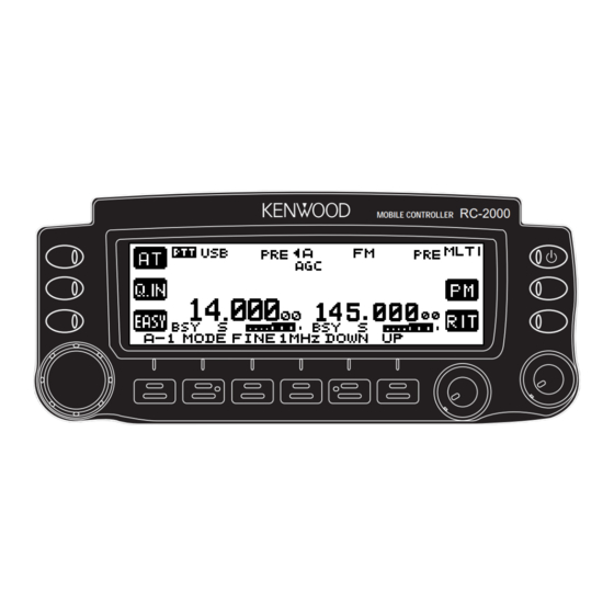
DISPLAY AND KEY FUNCTIONS #9 #8 #6 #5 #4 y !6 q “AT” appears when you operate HF ~ 50 MHz band. Press [L1] to activate the automatic antenna tuner. While it is in-line, “AT IN” or “AT R IN” appears (when Menu No. - Page 15 !7 Works as an S-meter in the receive mode. Works as the meter you selected while transmitting. !8 “ ” appears when the internal TNC is assigned to the main transceiver. !9 The Hz digits of the main transceiver operating frequency appears.
- Page 16 $0 “TRC” appears when the Trace function is ON in the Satellite mode. “TRCR” appears when the Reverse Trace function is ON in the Satellite mode. $1 “SATL” appears while operating in Satellite mode. $2 “PTT” appears when the sub-band is selected for the transmission band.
-
Page 17: Chapter 5 Cycling The Key Groups
12 keys and 5 controls. In order to access all the available functions of the transceiver from the RC-2000 mobile controller, the functions are divided into 3 groups: A, B, and C. Group A is a primary function group with most of the commonly used keys. -
Page 18: Group A Keys
GROUP A KEYS Group A–5 appears only when you recall Memory Channel 290 ~ 299. Detailed explanations of each function are provided on the following pages: – – – – – – – – – – , t i – –... - Page 19 GROUP A-1 MODE Press to change the operating mode pair. There are 3 pairs: USB/ LSB, FM/ AM, and CW/ FSK. Press and hold to toggle the mode within each pair: USB AM, or CW FSK. FINE Press to toggle the FINE tuning function ON or OFF. “F” appears on the display when this function is ON.
- Page 20 GROUP A-3 MENU Press to enter the Menu mode. Menu mode is used to activate and configure the various functions of the TS-2000(X)/ TS-B2000 {TS-2000 page 21}. Press [ADD] to add the current Menu No. to the Quick Menu. “ ” appears on the display when the Menu No. is added to the Quick Menu.
- Page 21 M.IN Press to enter the Memory Scroll mode {TS-2000 page 60}. “MSR” appears on the display. Turn the MULTI/ CH control to select your desired memory channel number. Press [M.IN] to write the data to memory. You can also press [MN.IN] to enter and select the Memory Name and Memory Group.
-
Page 22: Group B Keys
GROUP B KEYS “ANT1” or “ANT2” appears only when you are operating on the HF ~ 50 MHz band. “ANT” appears for all other bands in group B–1. Detailed explanations of each function are provided on the following pages: – –... - Page 23 GROUP B–1 Press to switch the receiver preamplifier ON or OFF {TS-2000 page 57}. “PRE” appears on the display when this function is ON. “P/A” appears on the display when both “PRE” and “ATT” are ON. Press to switch the receiver attenuator ON or OFF. “ATT”...
- Page 24 If the same band is selected for the TX band and Control band, only “PTT” appears on the display. LOCK Press to lock all the keys and controls of the RC-2000. Press and hold to unlock the keys and controls of the RC-2000.
-
Page 25: Group C Keys
GROUP C KEYS The available group C keys change, depending on the current operating mode. Detailed explanations of each function are provided on the following pages: USB/ LSB MODE – – – – – – – – – GROUP C–1 PROC Press to switch the Speech Processor function ON or OFF. - Page 26 T-MON Press to adjust the monitor level of your transmission signal. Adjust the monitor level using the [c]/ [d] keys or by turning the MULTI/ CH control, then press either [EXIT] or the MULTI/ CH control to store the setting. Press to adjust the output power {TS-2000 page 20}.
- Page 27 CW MODE – – – – – – – – – GROUP C–1 CW TUNE Press to activate the CW Auto Tune function. Press [CW TUN] again or [CLR] to exit the function. Press to enter the carrier level adjustment mode. Press Mic [PTT] to transmit.
- Page 28 GROUP C–2 Press to switch the CW break-in function ON or OFF. BK DLY Press to adjust the CW break-in delay time {TS-2000 page 42}. Select your desired break-in delay time using the [c]/ [d] keys or by turning the MULTI/ CH control, then press either [EXIT] or the MULTI/ CH control to change the setting.
- Page 29 FM MODE – – – – – – – – – – – g i f – GROUP C–1 PROC Refer to PROC in the USB/ LSB section {page 21}. Press to switch the Automatic Simplex function ON/ OFF. When it is ON, “[R]” appears. c i t t f i —...
- Page 30 GROUP C–2 Refer to VOX in the USB/ LSB section {page 22} . V GAIN Refer to V GAIN in the USB/ LSB section {page 22}. V DLY Refer to V DLY in the USB/ LSB section {page 22}. Press to select FM narrow bandwidth operation. “FMN” appears when you operate FM narrow bandwidth.
- Page 31 FSK MODE – – – – – – – – – GROUP C–1 Refer to CAR in the CW section {page 23}. Press to reverse the FSK shift. “FSR” appears when it is T-MON Press to adjust the monitor level of your FSK transmission signal.
- Page 32 GROUP C–2 Refer to RF in the CW section {page 24}. GROUP C–3 N.R. Refer to N.R. in the USB/ LSB section {page 22}. M.B.C. Refer to M.B.C. in the CW section {page 24}. FILTER Refer to FILTER in the CW section {page 24}.
- Page 33 AM MODE – – – – – – – – g i f – GROUP C–1 PROC Refer to PROC in the USB/ LSB section {page 21}. Refer to CAR in the CW section {page 23}. Refer to MIC in the USB/ LSB section {page 21}. i r r —...
- Page 34 GROUP C–2 Refer to VOX in the USB/ LSB section {page 22} . V.GAIN Refer to V.GAIN in the USB/ LSB section {page 22}. V DLY Refer to V DLY in the USB/ LSB section {page 22}. Press to perform AM narrow bandwidth operation. “AMN”...
-
Page 35: Chapter 6 Satellite Mode
SATELLITE OPERATION Amateur satellites receive on one band and transmit on another. This transceiver can handle uplink/ downlink frequency combinations simultaneously as shown below. ENTERING THE SATELLITE MODE 1 Press [F1] (1 s) until you select group B. 2 Confirm that you have selected group B–1. •... -
Page 36: Basic Operation
BASIC OPERATION When you enter the Satellite mode, you are always controlling one of 10 Satellite Memory channels with the adjustable frequency function. The Satellite Memory channel number (0 ~ 9) appears above the main band frequency display when you enter this mode. 1 Press [SATL] while in group B–1 to enter Satellite mode. -
Page 37: Satellite Channel Name
4 Press [OK] to store the name to the Satellite Memory channel. Press [CLR] to quit. 5 The stored Satellite Memory name appears above the main band frequency display on the RC-2000. QUICK MEMORY IN SATELLITE MODE While in the Satellite mode, only 1 Quick Memory channel is available. -
Page 38: Chapter 7 Easy Viewing Mode
OVERVIEW Since the RC-2000 is designed to be used in a vehicle, it has an unique Easy Viewing mode for mobile operation. When you enter this mode, the display shows only the current Control band frequency in a large font. Also, only 2 key function groups are available for quick function access. -
Page 39: Keys (L1 ~ L3)
Refer to the [UP] instructions {page 15}. Refer to the [CLR] instructions {page 16}. M>V Refer to the [M>V] instructions {page 16}. MENU Refer to the [MENU] instructions {page 16}. M.IN Refer to the [M.IN] instructions {page 17}. Refer to the [V/M] instructions {page 17}. KEYS (L1 ~ L3) AT/ AT IN/ AT R IN (L1 key) Press to activate the Automatic Antenna Tuner function... -
Page 40: Changing The Font Style
CHANGING THE FONT STYLE While you are in Easy Viewing mode, two different types of font styles are available. To change the font: 1 Press [MENU]. 2 Turn the MULTI/ CH control to select Menu No. 58. 3 Press [+]/ [–] to select “FONT2” or “FONT1” (default). 4 Press [OK] to accept the change. -
Page 41: Chapter 8 Packet Cluster Tune
PACKET CLUSTER TUNE FUNCTION DX Packet Cluster is a packet network consisting of nodes and stations who are interested in DXing and contesting. If one station finds a DX station on the air, he or she sends a notice to his or her node. This node then passes the information to all its local stations as well as to another node. -
Page 42: List Function In P.c.t. Mode
LIST FUNCTION IN P.C.T. MODE To access your desired DX information from the P.C.T memory in the P.C.T. mode: 1 Press [LIST] (L2). 2 Press [c]/ [d] or turn the MULTI/ CH control to select the report. • “s” indicates which DX report is currently selected. -
Page 43: Chapter 9 Overview
OVERVIEW While you are receiving, Visual Scan allows you to monitor frequencies near the current operating frequency. Visual Scan graphically and simultaneously shows how all frequencies in the selected range are busy. You will see up to 21 segments, for each channel, that represent 7 S-meter levels (3 segments per level). -
Page 44: Using Visual Scan
USING VISUAL SCAN 1 Select your desired frequency using the Tuning control. 2 Turn the Tuning control or press Mic [UP]/ [DWN] to select the operating frequency. • This frequency will be used as the center frequency for the Visual Scan. 3 Press [F1] (1 s) until you select group B. -
Page 45: Chapter 10 Programmable Memory (Pm)
Programmable Memory (PM) stores virtually all settings currently set on the transceiver. This transceiver provides 5 PM channels to store 5 sets of transceiver configurations. Later you can quickly recall one of these memories, depending on the operations you have in mind or the operating environment. -
Page 46: Application Examples
APPLICATION EXAMPLES The following are examples of how you might use Programmable Memory. Situation 1 Situation 1 You share your transceiver with other members in your family or club. However, each individual has personal preferences for how they like to set various functions. -
Page 47: Storing In Pm Channels
STORING DATA IN PM CHANNELS 1 Confirm that the following conditions have been satisfied: • The transceiver is in the receive mode. • Scan is not being used. • The Microphone Control is OFF. 2 Configure the transceiver as you like. •... -
Page 48: Chapter 11 Programming Call Signs
TS-570, TS-870, or TS-2000 series HF transceiver from a separate location. Before operating Sky Command II+ with the RC-2000, read the Sky Command II+ section of the TS-2000(X)/ TS-B2000 instruction manual, starting on page 83. After completing the setup, refer to pages... -
Page 49: Programming A Tone Frequency
PROGRAMMING A TONE FREQUENCY You must also program the CTCSS tone to operate the Sky Command II+. Select the same CTCSS tone for both the Commander and the Transporter. 1 Press [F1] (1 s) until you select group A. 2 Press [F1] until you select A–3. 3 Press [MENU]. -
Page 50: Starting Sky Command Ii+ Operation
STARTING SKY COMMAND II+ OPERATION 1 Select an open 144 MHz frequency on the main transceiver. 2 Select an open 440 MHz frequency for the sub- receiver. 3 Press [F1] (1 s) until you select group A. 4 Press [F1] until you select A–3. 5 Press [MENU]. -
Page 51: Usb/ Lsb Mode
USB/ LSB mode i t c – – – – – – – – – – – – – – – – – – – — – QUICK KEY REFERENCE i t c – – – – – – > –... -
Page 52: Cw Mode
CW mode i t c – – – – – – – – – – – – – – – – – – – – i t c – – – – – – – > – – – – –... -
Page 53: Fm Mode
FM mode i t c – – – – – – – – – – – – – – – – – – – – i t c – – – – – – – > – – – – –... -
Page 54: Fsk Mode
FSK mode i t c – – – – – – – – — — – — — – — — – – – – – – – – — – – i t c – – – – > –... -
Page 55: Am Mode
AM mode i t c – – – – – – – – – – – – – – – – – – – — – i t c – – – – – – > – – – – –... -
Page 56: Maintenance
You may return this product for service to the authorized KENWOOD dealer from whom you purchased it, or any authorized KENWOOD service center. Please do not send subassemblies or printed circuit boards only. Send the complete product. -
Page 57: Rc-2000 Mobile Controller
RC-2000 MOBILE CONTROLLER EXTERNAL SPEAKER SPECIFICATIONS – – ( " 5 " 4 " 0 , ) l " 5 " 6 " 3... -
Page 58: Appendix
[UP]/ [DWN]/ [1MHz]: Change the operating band 3 Press [OK] to store the settings. CONCERNING THE TM-D700A/E PANEL The RC-2000 control panel can be used in place of the TM-D700A/E panel. Switch the TM-D700A/E OFF then remove the TM-D700A/E panel. Plug the RC-2000... -
Page 59: Notices To User
If in doubt, do not wear headphones while mobiling. • Do not modify this mobile controller unless instructed by this manual or by other KENWOOD documentation. • Do not expose the mobile controller to long periods of direct sunlight nor place it close to heating appliances.