
Related Manuals for Kenwood TS-830


Summary of Contents for Kenwood TS-830
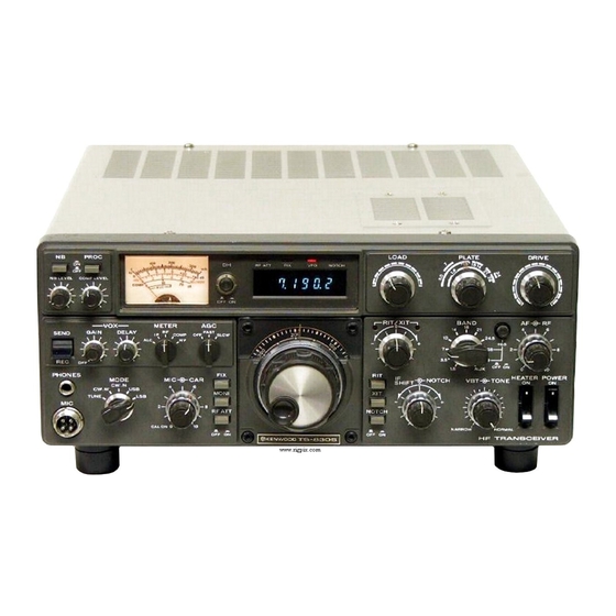
- Page 1 HF-Transceiver Kenwood TS-830 Survival Guide PART I edited by Olaf Rettkowski DL9AI...
- Page 2 VERSION Kenwood TS-830 Survival Guide, ed. Olaf Rettkowski, DL9AI, ver.1.2, 03 Dec 2002 REFERENCE This is a collection of material found on the net. For reference and further information visit the following sites and/or see the following papers: , Martin, G1XGX http://myweb.tiscali.co.uk/martin.atwsm/TS830S.html...
-
Page 3: Table Of Contents
Preface .........................6 Read first ! ........................6 History of this document ....................7 To-Do list ........................7 General Description....................7 Problems and known Fixes ..................8 Excessive delay in relay control signal to external amplifier--which causes hot switching in the amplifier's RF relays ................8 Frequency drift......................8 Frequency drift during warm-up...................9 TS-830S Frequency Drift - "FIX"... - Page 4 Low power output on 160 m only ................22 7.18 Crystals for FIX band selection ..................23 7.19 Changed DRIVE setting after final tubes replacement is normal ......23 7.20 Difference between TS-830 and TS-830 "gold label"..........23 7.21 Microphone impedance matching ................23 7.22 Problem with TS-830 TX relay ..................24 7.23 No operation on WARC bands...................24...
- Page 5 10.1.2 I miss mine, Rating: 5 of 5..................32 10.1.3 Good but aging, Rating: 5 of 5 ...................32 10.1.4 TS-830 The Best of the Best, Rating: 5 of 5...............32 10.1.5 Brilliant audio from 830, Rating: 5 of 5 ..............32 10.1.6 Excellent Radio on the used Market, Rating: 5 of 5...........32 10.1.7 Excellent Radio, Rating: 5 of 5...................32...
-
Page 6: Preface
First time using it I didn't really know what I was doing, but the TS-830 knew…and did what it was expected to do… It didn't take a long time until I encountered the first problems: there was no output in SSB-mode and I realized the low power output on the upper bands. -
Page 7: History Of This Document
• Adding of personal experience in using a TS-830: maybe someone has developed new procedures or can give hints helpful in operation. • Adding of detailed descriptions of the function of certain parts – which resistor or transistor has what function. -
Page 8: Problems And Known Fixes
Drawbacks: Slight frequency drift during warmup. This problem can be ameliorated by one of the fixes described below. 2. Inability to work split frequency at typical frequency differentials. 3. As with any ancient machine, maintenance requires an extra effort. However, newer radios appear to be far from trouble free. -
Page 9: Frequency Drift During Warm-Up
2. The grounding screws on the PC boards may not make good contact. (Bill W7US) 3. Although I have not seen this problem in a Kenwood, I have seen it in Icom and Yaesu- both with the same cause- small single turn variable caps. In case of the Yaesu it was a frequency... -
Page 10: Intermittent Shift In Display And Operating Frequency
Contact cleaner will fix this for a month or so but you need a new one. Intermittent shift in display and operating frequency (Author: Trio-Kenwood Communication, Inc.: “TS-830 frequency shift”) Some users may report an intermittent shift in the display and operating frequency. This may typically be a 1 to 4 KHz random shift. -
Page 11: Intermittent Alc On Transmit
Installation time for this procedure is 1/2 hour or less. Intermittent ALC on transmit 6.7.1 Problem 1: Intermittent ALC indication [TX] on only one band This indicates that the trouble is different than was the case in Problem 2 {which would be the same on all bands}. -
Page 12: Lack Of Crispness In Transmit Audio
This problem is caused by a cracked, plastic shaft-coupling between the RF unit and the final unit. Trio-Kenwood did not use Locktite, or a similar thread-locking compound, so the setscrews in the coupling had to be over-tightened, by the assembler, to prevent the setscrews from loosening during operation. -
Page 13: Peak-Distortion In The Rx Audio
6.13 Peak-distortion in the RX audio Cause: This is usually caused by one or more problems in the product-detector [PD] on the IF Unit. These problems are: 1. Unmatched PD mixer-diodes, and/or 2. Too-much 455 KHz injection-voltage at the local-oscillator {LO} port of the PD. 3. No terminating-resistor is used at the LO-port of the PD. -
Page 14: Rapid Jumps In Vfo Frequency
6.17 Rapid jumps in VFO frequency Cause(s): [1] This can be caused by fluctuation in the 9V regulated power-supply voltage, which is the result of an intermittent connection between the AF-AVR [automatic voltage- regulator] Unit's circuit-common and chassis ground. [2] The problem can also be caused by a dirty ground-connection wiper on the rotor of the VFO tuning-capacitor. -
Page 15: Receive Suffers Or Goes Out After Qro Modification
I would like to pass on the problem I had encountered in connection with the QRO modification to the Kenwood radios TS830S, TS-530S and the TS-530SP. The problem occurs after many hours of long winded QSO's. It seems that with the increase in the screen voltage from 210 to 300 volts, R37 on the RF unit (#X44-1360-00) heats up tremendously and will change it's value so greatly that even the receive either suffers or goes out totally. -
Page 16: Problems And Hints From Newsgroups
Beware of high voltage!!! Speaking of smoke… Years ago I laid my forearm across the plate connectors of a TS-830 that was in transmit mode (don't ask why...), 800 V DC plus RF, about 30 watts worth. Next thing I knew I was sitting on the floor, looking at my arm... the flesh was crawling around on it's own, quivering. -
Page 17: Slow Power Drop-Off
Slow power drop-off Question: I've been tuning my 830S through a good 50 Ohm dummy in the tune mode and pre- tuning the antenna tuner in this mode also so I would not damage the finals. The last two days I have noticed that after warmup, tune and pre-tune of the tuner the power will slowly drop of from 110 W to nearly 50 W. -
Page 18: Slow Power Drop-Off: Answer 4
FCC power regulations of the time read..75 W input power for a novice, and 1000 W input power for general and above. Even my Kenwood TL-922 amplifier says 2000 W input power. (Kenneth AB5CC) -
Page 19: Intermittend Drop Of Power Output
Intermittend drop of power output Question: …I seem to have intermittent problems with the power output. I typically would peak the RF output in CW mode, at approximately 265 mA plate current, and see roughly 130 W output on my less than state of the art MFJ-949E tuner. One day after a successful QSO and excellent 59 +20 signal report from Turks and Caicos Island on 14.203 MHZ (I'm located in Cincinnati, OH), I moved up to about 14.310 and when I tried to retune, found that I read only about 30 W on my meter…... -
Page 20: No Dip On The Plate Current And No Or Small Output
Answer 2: Check the driver valve base soldering under the RF board, I had the same problem and found hair line cracks in the soldering of the base connections, also there are a couple of resistors and a two pin plug to check right next to the base of the driver valve well if that doesn't work check the last wafer switch, for bad contacts. -
Page 21: Increasing Power Output / Qro-Modification, No.1
It's been said the TS-830 was one of Kenwood's finest achievements. I gotta agree, it's truly a pleasure to operate and has the looks of a serious piece of gear. Mine has been in operation since 1981 and is still going strong! (Mike W8MW) 7.13... -
Page 22: Intermittent Loss Of Audio
Low power output on 160 m only Question: I have a Kenwood TS-830S which puts out 100 W plus on all bands except 160, this is into a dummy load. Does any one have an answer to my problem? I haven't check out the... -
Page 23: Crystals For Fix Band Selection
Crystals for FIX band selection Question: I have a Kenwood 830S with a "fix" selection on the banc switch. This I am told is a fixed freq determined by a crystal that I can add to the unit. I think it is a 25/U type but no sure. -
Page 24: Problem With Ts-830 Tx Relay
Does anyone know if this radio needs to be modified or have something special done to work in those bands, or know where I should go from here? (Jeff WO5D) Answer 1: The earlier TS-830's had to be modified for WARC (30 m, 17 m, 12 m) TX. (Mark K9MQ) Answer 2: I have a TS-830S and had a similar problem. -
Page 25: Receiver Signal Attenuation When Keying The Microphone Or Rocking The Bandswitch
Receiver signal attenuation when keying the microphone or rocking the bandswitch Question: I have a problem with my Kenwood TS-830S. After tuning up, when I key the microphone, the receiver signals are sometimes greatly attenuated. When I rock the bandswitch slightly, the signals come back at normal reception / sensitivity levels. -
Page 26: Fan Lubrication
removing the VFO from the radio, {see section 6.17, page 14, Fix 2} the VFO drive system's gears and bearing surfaces should be lubricated with Tri-Flow, Break-Free or a similar, non- gumming lubricant, applied with a small watercolor brush. This procedure should be done once when the radio is new and once every approx. -
Page 27: Usb/Lsb Carrier Oscillator Alignment
Before going through a VBT alignment, you may wish to check your filter number. If your radio has a K5 filter, you can upgrade to the K12 filter. The Trio-Kenwood part number is L72-0333- 05. Kenwood dealers do not normally stock this filter. However, it can be ordered from the Trio- Kenwood Service Department. -
Page 28: Warc Modification
3. This will provide a very noticeable decrease in switching time. WARC modification In early TS-830's, the WARC transmit was not enabled. Solder a jumper wire from Pin 12 of IC- 23 to ground on the DIGITAL UNIT PCB. Ground can be obtained at Pin 8 of IC-4. (KF2TZ) -
Page 29: Kenwood Ts-830 Filter Modification
Note: These changes are at the owners option and may not be performed in-warranty. Kenwood TS-830 filter modification Here is an easy filter modification for the Kenwood TS-830S. First to use this mod, your rig need the YK-88C and to make it even better, the YG-455C installed. In short what we are going to do, is move around a 9 volt switching voltage. -
Page 30: Ts-830S Operation On 240 V Ac
VBT. TS-830S Operation on 240 V AC (Author: Trio-Kenwood Communication, Inc.) To operate the TS-830S on 240 V AC, the power transformer split primaries must be rewired from parallel to series connection. -
Page 31: Product Reviews
1. Applies to any unit before serial: 2010000*, 1120950*, 1132058*. 2. These changes may be performed in-warranty. Product Reviews 10.1 Opinions and Ratings of TS-830 owners (mainly from www.eham.net) 10.1.1 Great Radio, Rating: 5 of 5 (from KD6CCP, 2002) I have a TS-850s as my main base station. A Yaesu 100D mounted in the car but needed a good tube rig. -
Page 32: I Miss Mine, Rating: 5 Of 5
10.1.3 Good but aging, Rating: 5 of 5 (from NO9E, 2002) I bought a used TS-830 with 2 500 Hz filters and an Astatic mike. I compared it to TS-850. The TS-850 had slightly better TX signal due to high boost, more sensitive receiver, and slower dial. -
Page 33: A Quality Classic, Rating: 5 Of 5
10.1.8 A quality classic, Rating: 5 of 5 (from K4PDM, 2001) This is one of those rigs that I really wanted when they made them, but never managed to own one. I was lucky enough to pick one up at a hamfest about 3 weeks ago, and I'm extremely happy. -
Page 34: Nice Transceiver, Rating: 5 Of 5
Nice transceiver, Rating: 5 of 5 (from K9MNQ, 2000) I've enjoyed using my Kenwood TS-830 on HF and haved owned over 3 years. It covers all amateur bands from 160-10 meters and does not have a lot of buttons that have to be pressed to get the radio operational. -
Page 35: Good Radio
the metal can and the chassis, shorting the grid bias to ground. When I fired the rig up, the tubes "ran away" and started to melt down, then the fuses blew. Fortunately the person that designed the grid bias supply had a 10 KOhm resistor in series with the output, so I didn't smoke the power supply as well. -
Page 36: Connectors And Plugs
Connectors and Plugs (Kenwood Communications Inc.) -
Page 37: Index
Index 12BY7 16, 17, 18, 33 Microphone 23 6146 15, 16, 17, 18, 20, 23 mode switch 25, 29 6146B 12, 16, 17, 20, 21, 22, 25, 34 neutralization 16, 21, 23 6146W 16, 22 Noise Blanker 30 AF AVR unit 28, 30 output power 17, 18, 20, 21 AF-AVR Unit 12, 13 plate current 16, 17, 19, 20...