Table of Contents
Advertisement
Quick Links
FERROLI adheres to the
EUROVENT certification
programme.
The products concerned
appear in the products guide to
www.eurovent-certification.com
RLA
AIR WATER HEAT PUMPS
WITH HELICAL FANS
136 ÷ 299 kW IN COOLING MODE
165 ÷ 350 kW IN HEATING MODE
TECHNICAL MANUAL
150.4
165.4
180.4
205.4
230.4
260.4
285.4
315.4
Advertisement
Table of Contents

Related Manuals for Ferroli 150.4


Summary of Contents for Ferroli 150.4
- Page 1 AIR WATER HEAT PUMPS WITH HELICAL FANS 150.4 165.4 180.4 FERROLI adheres to the EUROVENT certification programme. 205.4 The products concerned appear in the products guide to www.eurovent-certification.com 230.4 260.4 285.4 315.4 136 ÷ 299 kW IN COOLING MODE 165 ÷ 350 kW IN HEATING MODE...
-
Page 3: Table Of Contents
TABLE OF CONTENTS THIS MANUAL IS DIVIDED INTO SECTIONS. THEIR NAMES APPEAR IN THE HEADING OF EACH PAGE. GENERAL SPECIFICATIONS ................4 PRESENTATION OF THE UNIT . -
Page 4: General Specifications
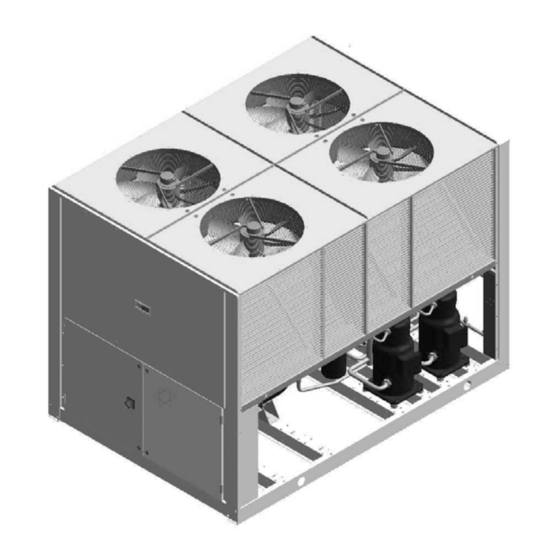
GENERAL SPECIFICATIONS Presentation of the unit This new series of industrial chillers has been designed to meet the air conditioning requirements of medium-large systems in the industrial, service and business sectors. Suitable for outdoor installation, they are built for various types of system and to comply with the needs of highly qualified planning engineers. The complete series for use in hydronic systems includes 8 sizes with refrigerating power ratings ranging from 136 to 299 kW and heating output ratings ranging from 165 to 350 kW. -
Page 5: Description Of The Components
GENERAL SPECIFICATIONS Description of the components 1. Fans. These are the helical type with scythe- shaped vanes to increase efficiency and reduce the sound emissions. The fans are directly coupled to the threephase motor by means of an external rotor. Thermal protection against opera- ting faults is installed inside the winding. - Page 6 GENERAL SPECIFICATIONS 4. Compressors. These are the SCROLL type with orbiting coil equipped with built-in thermal protection and oil heater. As part of the standard supply, they are positioned on rubber vibration dampers to reduce the vibrations transmitted to the base of the unit.
- Page 7 GENERAL SPECIFICATIONS Hydraulic and chilling circuit components 13. 4-way cycle reversing valves. Reverse the direction in which the refrigerant flows when the operating mode changes (Cooling mode or Heating mode). 14.Refrigerant safety valve. (Conforms to the Directive governing pressurized vessels -PED). Installed on the delivery pipe of the compressors.
-
Page 8: Options And Accessories
OPTIONS AND ACCESSORIES Mechanical accessories GM (M) Pressure gauge unit. Consisting of 4 pressure gauges that display the pressure of the refrigerant fluid on the intake and delivery of the compressors of both circuits.. GP (M) Protective grilles. Consisting of metal grilles that protect the coils with extended surfaces. AVM (F) Spring vibration dampers. -
Page 9: Description Of The Configurations
OPTIONS AND ACCESSORIES Description of the configurations MP - AM 2 Pumps with Water storage tank MP - AM 2 Pumps without Water storage tank KT with Water storage tank KT without Water storage tank KT. - Pipe kit, consists of two steel pipes insulated with heat barrier material. Allows the water IN / OUT connections to be rou- ted to the machine. -
Page 10: Electrical Accessories
OPTIONS AND ACCESSORIES Electrical accessories CR - Remote Control. This device consists of a remote control which allows all the control and monitoring functions of the control unit on the machine to be controlled up to 100 meters away from the actual machine itself. -
Page 11: Combinations Of Accessories-Models
OPTIONS AND ACCESSORIES Combinations of accessories-models MODEL ACCESSORY CODE • • • AVM 10 (F)(1)(4) • • • AVM 11 (F)(1)(4) • • • AVM 12 (F)(2)(4) • • • AVM 13 (F)(2)(4) Spring vibration dampers AVM 24 (F)(5) See tables below AVM 25 (F)(5) for models AVM 26 (F)(5) -
Page 12: Technical Specifications And Standard Performances - R407C
TECHNICAL SPECIFICATIONS AND STANDARD PERFORMANCES - R407C Technical specifications of Basic Version AB-7M5 Model Net cooling capacity Net heating capaciyt 60.4 66.5 72.7 82.3 93.5 In cooling mode Net total power input 62.8 67.5 72.4 81.9 89.9 In heating mode Maximum pressure on wet side 600 / 1000 (NB) -
Page 13: Standard Performances In Cooling Mode Ab-7M5
TECHNICAL SPECIFICATIONS AND STANDARD PERFORMANCES - R407C Standard performances in cooling mode AB-7M5 OUTDOOR AIR TEMPERATURE (°C D.B.) MODEL 40,9 45,4 50,8 56,6 60,6 64,6 41,3 46,2 51,2 57,4 61,0 65,0 41,7 46,6 51,6 57,8 61,4 65,8 42,1 47,0 52,0 58,2 62,2 42,9... -
Page 14: Standard Performances In Heating Mode Ab-7M5
TECHNICAL SPECIFICATIONS AND STANDARD PERFORMANCES - R407C Standard performances in heating mode AB-7M5 OUTDOOR AIR TEMPERATURE (°C D.B.) MODEL 40,2 40,9 41,5 41,8 42,2 42,9 45,5 46,4 47,2 47,5 48,0 48,8 50,9 51,9 53,1 53,6 54,0 54,8 57,7 58,9 60,3 60,8 61,4 62,3... -
Page 15: Technical Specifications Of Unit As-7M5
TECHNICAL SPECIFICATIONS AND STANDARD PERFORMANCES - R407C Technical specifications of Silenced Version AS-7M5 Model Net cooling capacity Net heating capaciyt 62.4 67.5 72.7 82.9 93.7 In cooling mode Net total power input 58.6 63.1 69.0 78.3 87.7 In heating mode Maximum pressure on wet side 600 / 1000 (NB) -
Page 16: Standard Performances In Cooling Mode As-7M5
TECHNICAL SPECIFICATIONS AND STANDARD PERFORMANCES - R407C Standard performances in cooling mode AS-7M5 OUTDOOR AIR TEMPERATURE (°C D.B.) MODEL 45,8 51,0 56,7 63,3 67,3 72,0 46,3 51,5 57,1 63,7 68,3 72,9 46,7 51,9 57,6 64,2 68,7 73,3 47,2 52,4 58,1 64,6 69,2 47,6... -
Page 17: Standard Performances In Heating Mode As-7M5
TECHNICAL SPECIFICATIONS AND STANDARD PERFORMANCES - R407C Standard performances in heating mode AS-7M5 OUTDOOR AIR TEMPERATURE (°C D.B.) MODEL 40,0 40,9 41,8 42,2 42,8 43,7 45,4 46,4 47,4 47,8 48,4 49,4 50,8 51,9 53,3 53,3 54,0 55,2 57,7 58,9 60,4 60,9 61,5 62,6... -
Page 18: Operating Range
OPERATING RANGE Operating range The graphs below give the operating ranges within which correct operation of the units is guaranteed. The use of the units in conditions differing from those indicated will void the warranty with which the product is supplied. In the following table, there are the thermal water head limit values of the unit. - Page 19 HOW TO SELECT THE UNIT 1) The Standard Performances tables in the Technical data and standard performances chapter give the Useful output capacity in the cooling mode and Heating output in the heating mode values with the relative com- pressor input power values of each unit in standard conditions. The data can be interpolated but not extrapola- ted.
-
Page 20: How To Select The Unit
HOW TO SELECT THE UNIT Beginning with the refrigerating power required by the given conditions of use and having checked the Standard performances table, model IP 205 VB AB 7M5 can be selected as it provides a standard refrigerating power of (171.4 kW). - Page 21 HOW TO SELECT THE UNIT With reference to the Maximum water volume section drawing and supposing that the difference in level between the highest point in the circuit and the unit is 20 meters (case B of table 5), the chamber must be given a 226 kPa setting while the maximum amount of water in the system (including the volume of the tank of the pumping modu- le) will be 768 liters (V ).
- Page 22 HOW TO SELECT THE UNIT Tab.4 Correction factor F Outdoor air temp. Relative humidity % 0.905 0.932 0.960 0.944 0.952 0.960 0.972 0.966 0.960 0.980 1.022 0.963 0.961 0.959 0.942 0.947 0.952 0.924 0.935 0.946 If the system is not drained during winter, but is stopped and brine is used, it will be necessary to introduce multi- plicative correction factors for the Refrigerating Power (F ).
-
Page 23: Water Pressure Drop
WATER PRESSURE DROP The graph below illustrates the loss of head values in kPa depending on the flow rate in liters/second. The operating range is delimited by the minimum and maximum values given in the next table. Water flow rate (l/s) Limits to operation Model NOTES... -
Page 24: Working Head
WORKING HEAD The graph below illustrates the useful head values (kPa) depending on the flow rate in (liters/second). The operating range is delimited by the minimum and maximum values given in the next table. Useful head is the one at the outlet of the standard pumping module minus all the loss of head values of the unit. 10,0 12,0 14,0... -
Page 25: Maximum Volume Of Water
MAXIMUM VOLUME OF WATER Maximum volume of water in the system with wet module Before filling the water system, it is advisable to consider the type of installation in question, i.e. check the difference in level bet- ween the wet module and user. The following table gives the maximum water content of the water supply system in liters, depen- ding on the capacity of the standard surge chamber supplied and the pressure at which it should be charged. -
Page 26: Overall Dimensions - Minimum Space Required And Weights
OVERALL DIMENSIONS - MINIMUM SPACE REQUIRED AND WEIGHTS Overall dimensions Mod. 150.4 ÷ 260.4 2949 Max. 1800* 1946* 2947 2050 =ł18mm Center distance of vibration damper holes Mod. 285.4 - 315.4 2230* 2290* 2350 2995 =ł18mm Center distance of vibration damper holes... -
Page 27: Position Of Wet Connections Mod. 150- 260
OVERALL DIMENSIONS - MINIMUM SPACE REQUIRED AND WEIGHTS Position of wet connections Mod. 150÷260 Unit with Pipe kit. Unit with return storage Pumping Module Unit with delivery storage Pumping Module Unit with primary/secondary Pumping Module The unit s water inlet (IN) and outlet (OUT) occur through 3 flexible Victaulic couplings (DN 80). -
Page 28: Position Of Wet Connections Mod. 285-315
OVERALL DIMENSIONS - MINIMUM SPACE REQUIRED AND WEIGHTS Position of wet connections Mod. 285-315 Unit without Water Storage Tank Unit with Pipe kit. 1619 1376 Unit with pumping module with 1 o 2 Pumps 1619 1376 2369 The unit s water inlet (IN) and outlet (OUT) occur through 4 flexible Victaulic couplings (DN 100). Unit with Water Storage Tank Unit with Pipe kit. - Page 29 OVERALL DIMENSIONS - MINIMUM SPACE REQUIRED AND WEIGHTS Unit with pumping module Accumulation on the Plant Return side with 1 o 2 Pumps 1620 1375 2369 Unit with primary/secondary Pumping Module with 1 o 2 Pumps 2199 The unit s water inlet (IN) and outlet (OUT) occur through 4 flexible Victaulic couplings (DN 100).
-
Page 30: Weight Distribution During Operation
OVERALL DIMENSIONS - MINIMUM SPACE REQUIRED AND WEIGHTS Weight distribution during operation Consider the following center of gravity position values and load on the bearing surfaces to correctly match the machine to the bearing structure, with reference to the figure: Load on bearing points in kg Model 1006... - Page 31 The manufacturer declines all responsibility for any inaccuracies in this manual due to printing or typing errors.
- Page 32 FERROLI S.p.A. Via Ritonda, 78/a - 37047 San Bonifacio - VERONA (Italy) Tel.045/6139411 (r.a.) Fax 045/6100233 - 6100933 - Tlx 480172...