
Related Manuals for Ferroli HSW 3.1


Summary of Contents for Ferroli HSW 3.1
- Page 1 WATER - WATER AND BRINE - WATER HEAT PUMPS R410A FOR INDOOR INSTALLATION INSTALLATION AND OPERATION MANUAL...
- Page 2 Dear Customer, Thank you for having purchased a FERROLI product. It is the result of many years of experiences and of particular research studies and has been made with top quality materials and advanced technologies. The CE mark guaran- tees that the products satisfy all the applicable European Directives.
-
Page 3: Table Of Contents
TABLE OF CONTENTS GENERAL FEATURES ................4 GENERAL INSTRUCTIONS . -
Page 4: General Features
GENERAL FEATURES General instructions This manual and the wiring diagram supplied with the unit must be kept in a dry place for possible future consultations . The manual provides information on installation and correct use and maintenance of the unit. Before carrying out installation, please carefully read all the information contained in this manual, which describes the procedures necessary for cor- rect installation and use of the unit. -
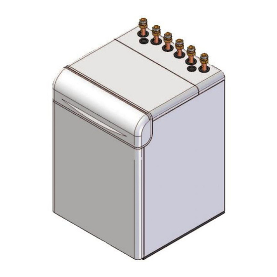
Page 5: Unit Description
GENERAL FEATURES Unit description This series of water-water heat pumps satisfies the heating, daily switching programs for heating, cooling and domestic hot cooling and domestic hot water production requirements of water production. residential plants of small and medium size. The refrigerant circuit, contained in an extractable box to sim- All the units are suitable for indoor installation and can be plify the maintenance operations, is equipped with rotary com- applied to fan coil plants, radiant floor plants and high effi-... -
Page 6: Description Of Components
GENERAL FEATURES Description of components External structure. Basement, lateral panels and frontal heat pumps), pressure connections SAE 5/16” - UNF 1/2” - panel, are completely thermally and acoustically insulated in 20 equipped with pin, gasket and blind nut, as required for the order to minimize thermal losses and noise emissions in the use of R410A refrigerant (they allow the complete check of the surroundings. -
Page 7: Control System
GENERAL FEATURES Control system The microprocessor controller is able to manage not only the unit itself but also all that components of the plant which allow to realize a complete system. The main functions of the control system are : 18:28 room temperature control according to the outdoor tempe- 20.5 C... -
Page 8: Options
GENERAL FEATURES Options Pump Allows the circulation of the water on the source side. Source side flow rate management Modulates the water flow rate on the source side when the water circulation 2 way valve is assured by an external pump. Allow to divert the hot water produced by the heat pump from the heating cir- 3 way valve cuit to the domestic hot water circuit. - Page 9 GENERAL FEATURES Option “Domestic hot water production” 3 way valve In this configuration the heat pump can be coupled to a domestic hot water tank equipped with a coil desi- gned for a maximum water tempera- ture between 55°C and 60°C. The anti legionella cycles have to be performed by means of electrical heaters placed on the heat pump...
-
Page 10: Accessories
GENERAL FEATURES Accessories Allows operating mode selection and set point adjustment. The on board temperature sensor can be used in Remote thermostat order to realize a climatic control. Remote control Replicates all the control and visualization functionalities of the controller installed on the unit. The on board (wired or wireless) temperature sensor can be used in order to realize a climatic control. -
Page 11: Technical Data And Performances
TECHNICAL DATA AND PERFORMANCES Technical data Frame 11.1 Model U.M. Power supply 230 - 1 - 50 230 - 1 - 50 230 - 1 - 50 230 - 1 - 50 230 - 1 - 50 V-ph-Hz Refrigerant Type R410A R410A R410A... -
Page 12: Nominal Performances - Low Temperature Plants
TECHNICAL DATA AND PERFORMANCES NOMINAL performances - low temperature plants Frame 11.1 Model U.M. Power supply 230 - 1 - 50 230 - 1 - 50 230 - 1 - 50 230 - 1 - 50 230 - 1 - 50 V-ph-Hz Heating W10W35 ( source : water in 10°C out 7°C / plant : water in 30°C out 35°C ) -
Page 13: Nominal Performances - Medium Temperature Plants
TECHNICAL DATA AND PERFORMANCES NOMINAL performances - medium temperature plants Frame 11.1 Model U.M. Power supply 230 - 1 - 50 230 - 1 - 50 230 - 1 - 50 230 - 1 - 50 230 - 1 - 50 V-ph-Hz Heating W10W45 ( source : water in 10°C out 7°C / plant : water in 40°C out 45°C ) -
Page 14: Heating Performances
TECHNICAL DATA AND PERFORMANCES HEATING performances Heating capacity ( brine ) Heating capacity (water ) Inlet temperature - source side [°C] Inlet temperature - source side [°C] Power input ( brine and water ) The graphs allow to get the corrective factors to be applied to the nominal performances in order to obtain the real perfor- mances in the selected operating conditions. -
Page 15: Cooling Performances
TECHNICAL DATA AND PERFORMANCES COOLING performances Cooling capacity ( brine and water ) The graphs allow to get the corrective factors to be applied to the nominal performances in order to obtain the real perfor- mances in the selected operating conditions. The reference nominal conditions are : - water-water units : W30W7 (source : water in 30°C out 35°C / plant : water in 12°C out 7°C) -
Page 16: Plant Side Hydraulic Performances
TECHNICAL DATA AND PERFORMANCES Plant side hydraulic performances Available static head - unit without options 11.1 1000 1500 2000 2500 3000 3500 Flow rate [ l/h ] Pressure drops A = unit with option “Domestic hot water production” : “3 way valve” B = unit with option “Integrative electrical heaters”... -
Page 17: Source Side Hydraulic Performances
TECHNICAL DATA AND PERFORMANCES Source side hydraulic performances Pressure drops - unit without options 11.1 1000 1500 2000 2500 3000 3500 Flow rate [ l/h ] Available static head - unit with option “Source side flow rate management” : “Pump” 11.1 1000 1500... -
Page 18: Domestic Hot Water Side Hydraulic Performances
TECHNICAL DATA AND PERFORMANCES Pressure drops - unit with option “Passive cooling” 1000 1500 2000 2500 3000 3500 Flow rate [ l/h ] Domestic hot water side hydraulic performances Available static head A = unit with option “Domestic hot water production” : “3 way valve” B = unit with option “Domestic hot water production”... -
Page 19: Operating Limits
TECHNICAL DATA AND PERFORMANCES Operating limits The graphs reported below show the operating area inside which the correct working of the unit is guaranteed. The dotted lines show the operating area when brine solutions in the source side hydraulic circuit are used. HEATING Inlet temperature - source side [°C] COOLING... -
Page 20: Electrical Data
TECHNICAL DATA AND PERFORMANCES Electrical data Frame 11.1 Model U.M. Unit Power supply 230 - 1 - 50 230 - 1 - 50 230 - 1 - 50 230 - 1 - 50 230 - 1 - 50 V-ph-Hz F.L.A. Maximum total current input 10,1 13,3... -
Page 21: Weights
TECHNICAL DATA AND PERFORMANCES Weights Frame 11.1 Model U.M. Components weights Unit Unit without options Pump Source side flow rate management 2 way valve 3 way valve Domestic 3 way valve with pri- hot water mary heat exchanger production 3 way valve with secon- dary heat exchanger Passive cooling Integrative electrical heaters... -
Page 22: Overall Dimensions
TECHNICAL DATA AND PERFORMANCES Overall dimensions Plant return 1” M Plant flow 1” M 1 2 3 4 5 6 Domestic hot water return 1” M Domestic hot water flow 1” M Source return 1” M Source flow 1” M Solar panel return 1”... -
Page 23: Connections
CONNECTIONS Hydraulic connections To design properly the hydraulic system respect the local Expansion vessels setting safety regulations in force. All the units are equipped with expansion vessels (source side It is always necessary to guarantee an appropriate water flow and plant side). through the plate heat exchangers of the unit even if on both The precharge pressure of the expansion vessel must be ade- the hydraulic circuits (source side and plant side) is installed,... -
Page 24: Electrical Connections
CONNECTIONS Electrical connections The electrical wirings must be carried out by qualified person- Integrative electrical heaters power supply nel according to the regulations in force at the installation time The power supply cables must have an adequate section for in the country of installation. Before starting any work on the the power absorbed by the only integrative electrical heaters electrical circuit make sure that the unit power supply line is and must be chosen in conformity with the regulations in force. -
Page 25: Receiving And Positioning
RECEIVING AND POSITIONING Receiving Check on receiving The unit is supplied on a pallet suitable for the transport. It is As soon as the unit is received verify accurately the corre- advisable to place protective material between the truck and spondance of the load to what was ordered to make sure that the unit to avoid damages to the unit. -
Page 26: Start Up
START UP Start up The following operations must be carried out only by properly trained personnel. To make the contractual warranty effective, start up must be carried out by authorized service centres. Before calling the service centre it is advisable to make sure that all the installation steps have been completed (positioning, elec- trical connections, hydraulic connections). -
Page 27: Control System
CONTROL SYSTEM Control system configuration The control system can be configured in different ways in order to adapt itself to the user needs and to the kind of plant mana- ged by the heat pump. The simpler configuration consists of unit controller (A), outdoor air temperature sensor (B) and user interface (C). -
Page 28: Heating And Cooling Circuits
CONTROL SYSTEM Heating and cooling circuits The controller of the heat pump is able to manage two circuits in HEATING and one circuit in COOLING. The management of further heating or cooling circuits, possible by means of additional expansion modules, is not treated in this manual. - Page 29 CONTROL SYSTEM Configuration 3 Configuration 5 Zone 1 : management through remote control Zone 1 : management through user interface Zone 2 : not present Zone 2 : management through remote control or thermostat Zone 1 Zone 1 Zone 2 HC1/CC1 HC1/CC1 Remote...
-
Page 30: Control System Devices Installation
CONTROL SYSTEM Control system devices installation REMOTE THERMOSTAT AND REMOTE CONTROL ( WIRED OR WIRELESS ) They should be located in the main room of the zone they manage taking into account the following criteria : - the place of installation should be chosen so that the sensor can min. - Page 31 CONTROL SYSTEM OUTDOOR AIR SENSOR The device must be installed outside the building. The sensor is connected to the controller of the unit or to the wireless adaptor through a two wire cable ( the wires are interchangeable ). Ø 14,1 79,8 49,7 24,5...
-
Page 32: Wireless Devices Connection
CONTROL SYSTEM Wireless devices connection The wireless devices should be located in such a way that the In order to fulfill the connection two stages are necessary. transmission is as interference free as possible. The following Connection establishment : wireless devices are connected criteria must be observed : to the controller of the heat pump. -
Page 33: Control System Using
CONTROL SYSTEM Control system using The user interface, placed on the frontal panel, allows the rature sensor to measure the room temperature of the zone complete control of the system permitting to visualize and managed by the remote control and the replacement of the modify all the operating parameters of the unit. - Page 34 CONTROL SYSTEM USER INTERFACE AND REMOTE CONTROL DISPLAY Heating : Comfort set point Heating : Reduced set point Heating : Frost Protection set point Cooling : Comfort set point Wait Xxxxxxxxxxxxxxxxxxxxxxxxxxx Change batteries Xxxxxxxxxxxxxxxxxxxxxxxxxxx Xxxxxxxxxxxxxxxxxxxxxxxxxxx Holiday function active Reference to heating circuit REMOTE THERMOSTAT DISPLAY Alarm messages Maintenance messages...
- Page 35 CONTROL SYSTEM DHW button Allows to select the domestic hot water heating mode (indicated by a bar under the corresponding symbol). Domestic hot water heating mode ON - domestic hot water temperature controlled according to the set time table - protective functions active Domestic hot water heating mode OFF - protective functions active Domestic hot water heating mode FORCED...
-
Page 36: Control System Programming
CONTROL SYSTEM Control system programming The settings that can not be modified directly through the buttons of the user interface and of the remote controls are accessi- ble through the programming parameters, grouped inside the various programming menus. The menus concerning functions which are not active are automatically hidden. - Page 37 CONTROL SYSTEM Menu Level Parameter Function Preselection Phase 1 on Phase 1 off Time table 5 Phase 2 on Phase 2 off Cooling circuit 1 Phase 3 on Phase 3 off Default values Start Holidays program Heating circuit 1 Operating level Start Holidays program Heating circuit P...
-
Page 38: Remote Thermostat Programming
CONTROL SYSTEM Remote thermostat programming The configuration parameters of the remote ther- Parameter Function mostat must be set on the device itself. Remote thermostat use A long press (longer than 3 seconds) on the ru = 1 management heating circuit 1 OCCUPANCY button allows to enter the ru = 3 management heating circuit P Programming menu from which is possible to... - Page 39 CONTROL SYSTEM Holidays setting It is possible to set a holidays period for the heating circuit 1 and for the heating circuit P. For each period it is possible to specify the start and the end date and the set point to be adopted during the holidays period. Operating mode selection for heating and cooling circuits Heating circuit 1 : through the Heating button...
-
Page 40: Inputs And Outputs
CONTROL SYSTEM Inputs and outputs The following table shows the list of the inputs and outputs available on the controller of the heat pump along with the expected use. Some inputs and outputs can be configured in a different way by the user in order to manage other plant components which are not contained inside the heat pump. -
Page 41: Alarms
CONTROL SYSTEM Alarms Alarms activation and reset alarm icon is no more shown on the display. Some of these The controller is able to perform a complete diagnosis of the alarms become manual reset alarms if the number of events unit detecting all the operating faults and notifying different in an hour exceeds a fixed threshold. -
Page 42: Controller Technical Data
CONTROL SYSTEM Controller technical data Controller 230 Vac (+10% / -15%) Power supply 50 Hz / 60 Hz max 11 VA Safety class (EN 60730) Degree of protection (EN 60529) IP 00 Operating room temperature (not condensing) -20°C ... 50°C Storing room temperature -20°C ... -
Page 43: Sensors Features
CONTROL SYSTEM Wireless repeater 230 Vac (+10% / -15%) Power supply 50 Hz (+6% / -6%) max 0,5 VA wireless BSB bus Communication frequency 868 MHz Safety class (EN 60730) Degree of protection (EN 60529) IP 20 Operating room temperature (not condensing) 0°C ... -
Page 44: Maintenance
MAINTENANCE Maintenance IMPORTANT BEFORE CARRYING OUT MAINTENANCE OR CLEANING OPERATIONS MAKE SURE THE UNIT POWER SUPPLY IS DIS- CONNECTED. ANY ORDINARY OR EXTRAORDINARY MAINTENANCE OPERATION MUST BE CARRIED OUT BY SPECIA- LIZED AND AUTHORIZED PERSONNEL IN ORDER TO ENSURE COMPLIANCE WITH THE SAFETY REGULATIONS IN FORCE. -
Page 45: Safety And Pollution
SAFETY AND POLLUTION General considerations Accessing the unit The access to the unit must be granted exclusively to qualified personnel trained to operate on this type of units and provided with the necessary protection equipment. Moreover such personnel, to operate, must be authorized by the owner of the unit and recognized by the Manufacturer. - Page 46 SAFETY AND POLLUTION 8 CONTROL OF EXPOSURE / PERSONAL PROTECTION Personal protection Ensure adequate ventilation, especially in closed areas. Control parameters Difluoromethane (R32): Recommended exposure limits: AEL (8h and 12h TWA) = 1000 ml/m3 Pentafluoroethane (R125): Recommended exposure limits: AEL (8h and 12h TWA) = 1000 ml/m3 Respiratory tracts protection For rescue and for maintenance works in tanks, use self-contained breathing apparatus.
- Page 48 Ferroli spa ¬ 37047 San Bonifacio (Verona) Italy ¬ Via Ritonda 78/A tel. +39.045.6139411 ¬ fax +39.045.6100933 ¬ www.ferroli.it...